Both the Pico and theXIAO are fairly
cheap and comparable in both size and cost. However, the Pico has enough pins that are compatible with I2C and SPI. Hence, the Pico was chosen.
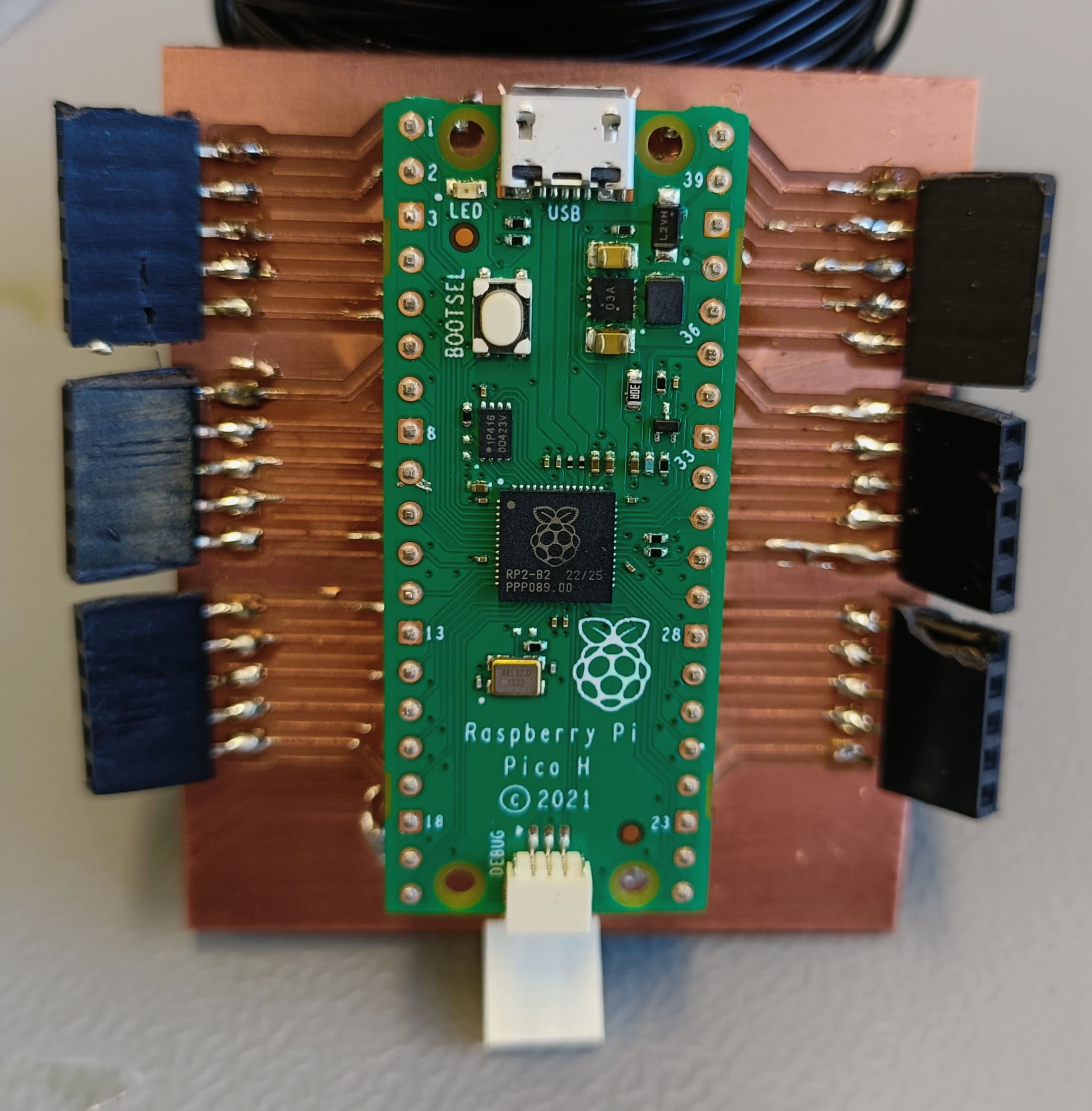
So, I made a test board for 2 versions of the Pico:
Left: test board for the Pico H; Right: preview of the test board for the Pico Zero
When it was my turn to present in the global class, Neil recommended to reduce the complexity for instances by using a XIAO instead of the Pico.
I was hesitant at first because pins were missing. Then, I read somewhere that as long as all RFID modules can have the same ID, they can be
connected to the same pin in parallel. Unfortunately, I can not find that source anymore, but I will keep looking for it and link it when I found it.
This development means, that the the microprocessor used in the next general schematic will be a XIAO.
RFID modules
Current status:
Will be using the RFID MFRC522 modules for communication. For comparison, testing will be completed with sticker RFID modules based on the same IC
that only cost a fraction of the MFRC522 modules.
Storytime:
Oldest to Newest: Top to bottom
Comparison of communication Technology. Wifi, Bluetooth, and Zigbee have been disqualified due to set-up.
Protocol
Pros
Cons
Sources
RFID
Connection will only be established within a distance of 2-7cm
The same device can both receive and send data
Is reliable
Simple connection possible through phone app
Connection can also be established with tags/ cards
Due to the fact that the ESP-NOW protocol does not support higher number of participants, the RFID protocol was chosen.
Additionally, the RFID protocol has the advantage that it automatically restrict communication to only the immediate neighbors
due to its limited range. This simplifies the coding a lot.
Conclusion: MFRC522. Cheap and covers all requirements. It is also the most common one, so there is a huge online community supporting it.
Requirement of microcontroller: Total of SPI and I2C capable pins is at least 4.
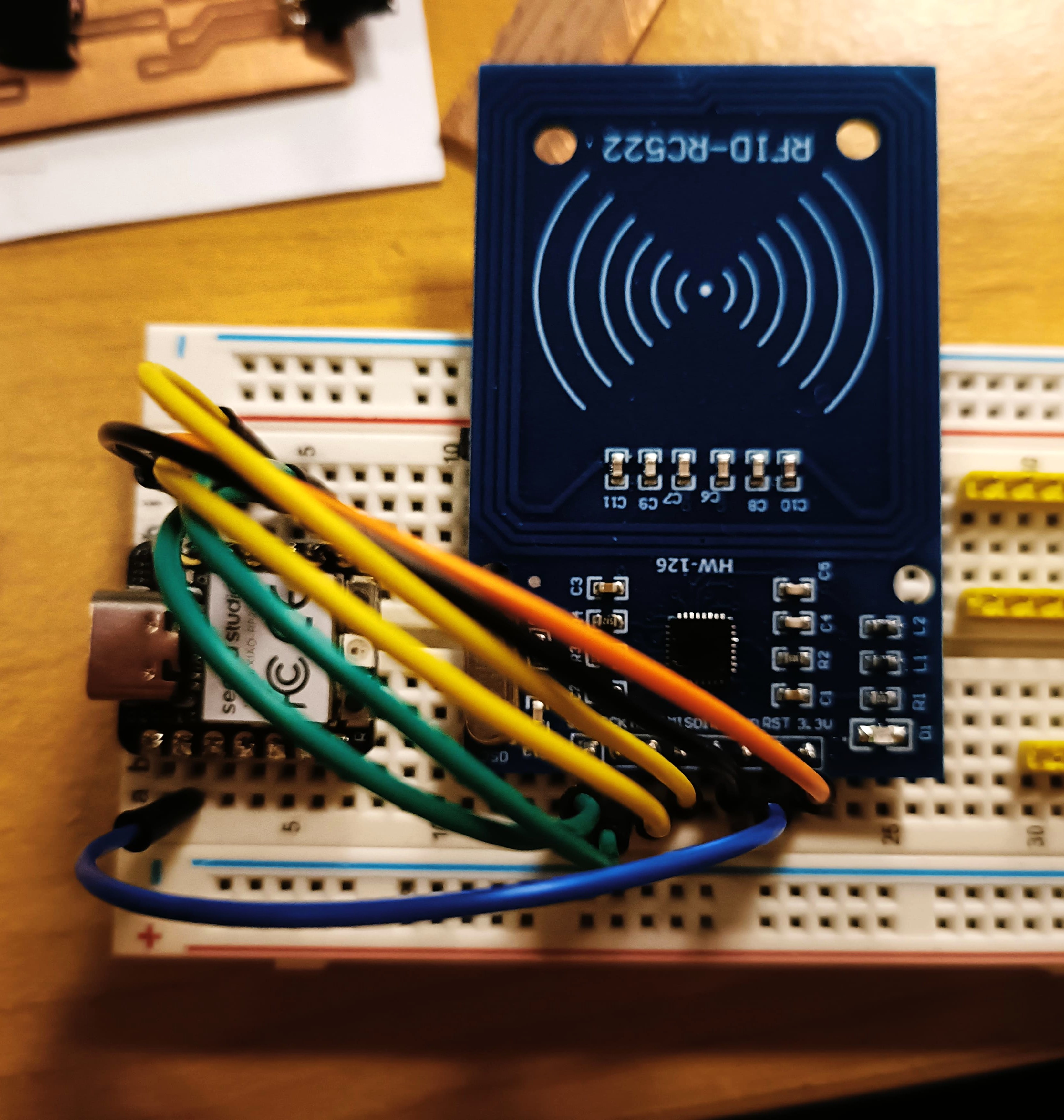
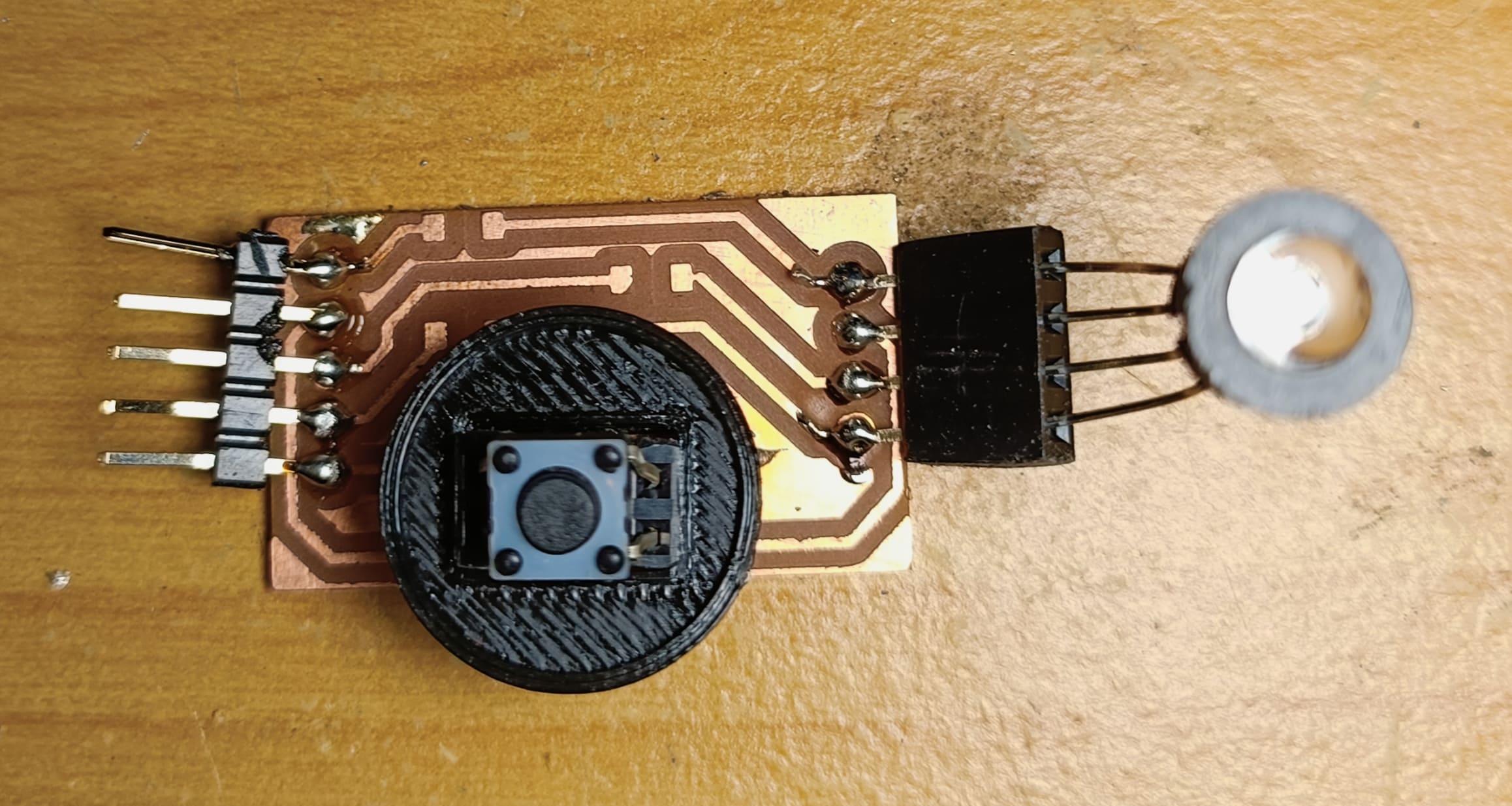
Testing RFID modules:
Left: Testing on a breadboard with the XIAO; Right: Testing on a pcb from Neil with a ATTiny
Later, I read somewhere that if the RFID modules themselves can all share the same ID number, they can all be connected to the same pins
of the microcontroller. This set this choice in stone.
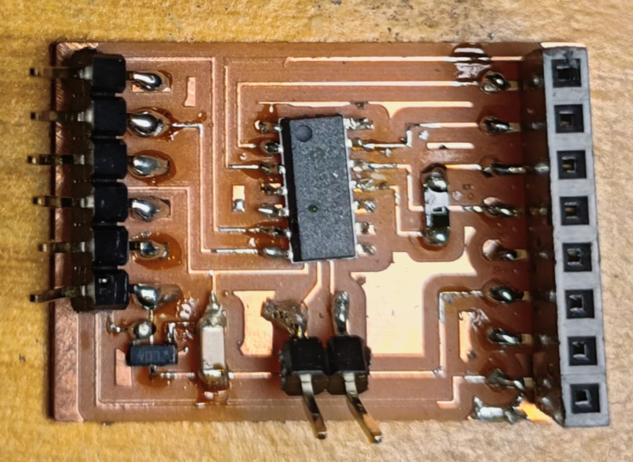
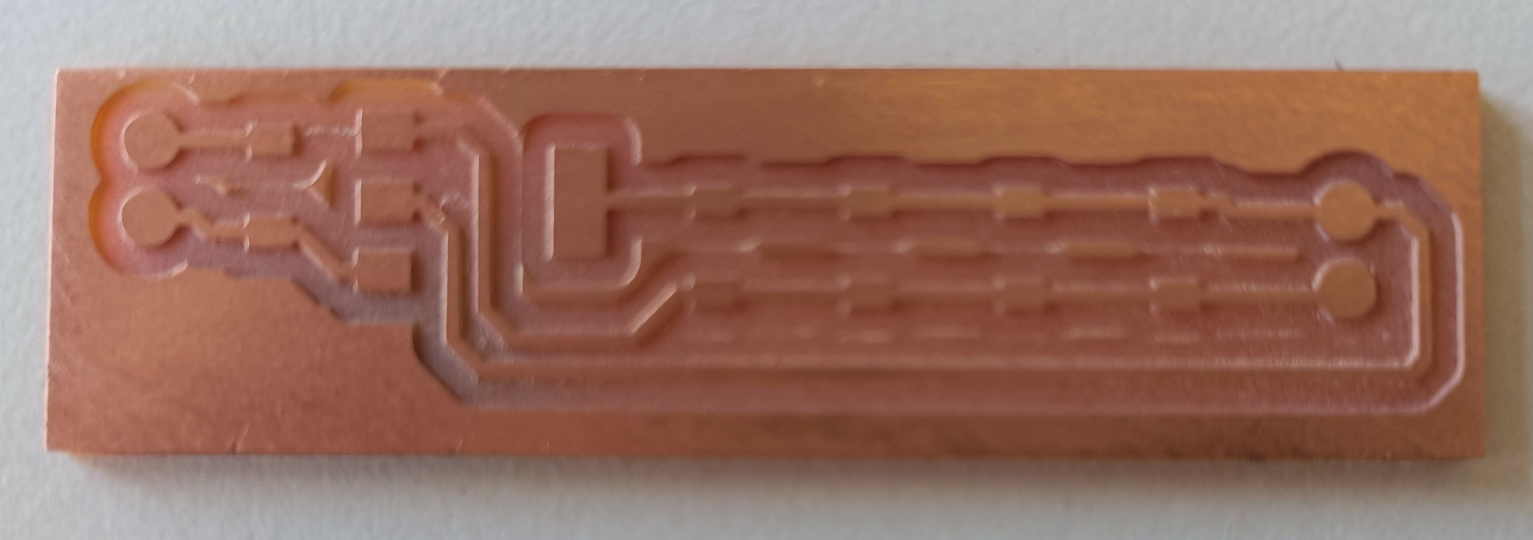
Linear Voltage Regulator to 3.3V
Current status:
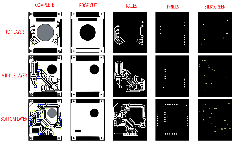
Produced pcb to test
Storytime:
Oldest to Newest: Top to bottom
Found this component on the Fab Inventory and pulled up the datasheet. There, it said how to wire it up.
This is going to be a swarm, hence there is going to be a lot or robots active at all times during usage.
To minimize overlay lay time and patience while changing the batteries, a self-charging circuit is required.
The ideal battery for this project should be cheap, light, rechargeable, and durable.
With this limitations only button batteries, AA, AAA, and LIPO batteries will be taken into consideration.
However, the final choice for the batteries will be decided by safety and speed of their respective charging circuits.
There seems to be predominantly 2 chips on the market that is recommended for charging LIPO batteries.
TP4056. There seems to be some debate online on how to use it safely.
It required a precise clock. Here are some basic tutorials to get started:
Started by comparing communication technologies and available microcontrollers, RFID modules, LED constellations, charging circuits, and voltage regulator systems.
For more information please go to the submodules section.
Started by doing a general schematic to get an overview:
V1 general schematic
I was told to reduce the complexity of the project, so I decided to test the different submodules separately first.
For more information please go to the submodules section. Neil recommended using the XIAO and simulate the SPI connection in code to require less pins.
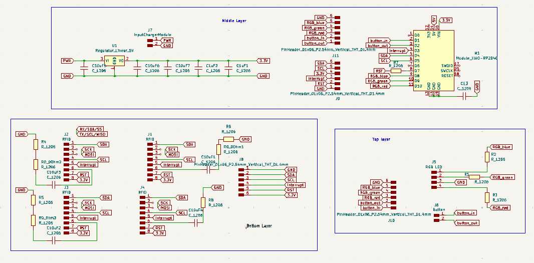
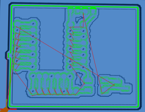
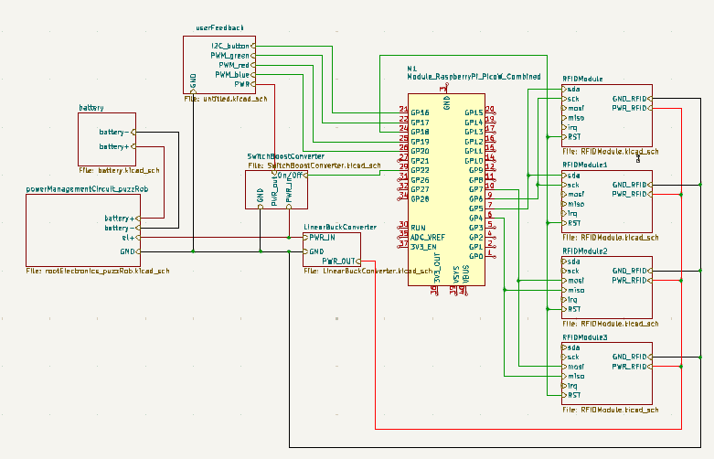
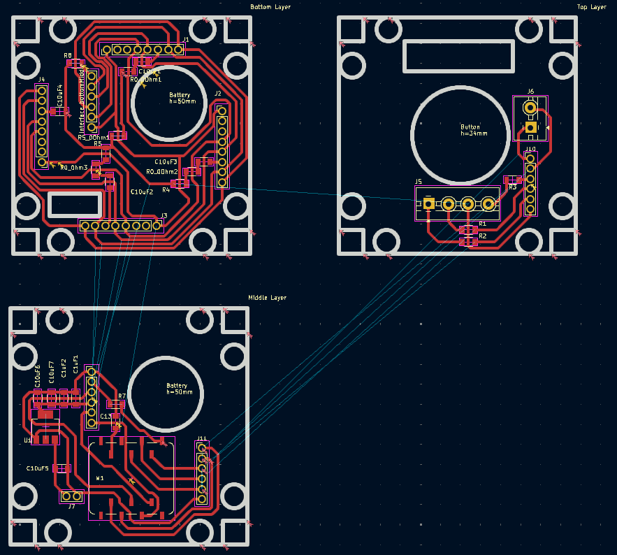
After finishing working on the individual submodules, it was time to make a V2 on the general schematic:
V2 of general schematic puzzling Robots and footprint. Made with KiCad
Error: The interfaces between the layers where not stacked cleanly
Additionally, even tough I dimensioned it with the measurements of the chassis,
I neglected to take into account that the RFID modules at the side do take up space and block
some space at the sides. The measurements have to be redone.
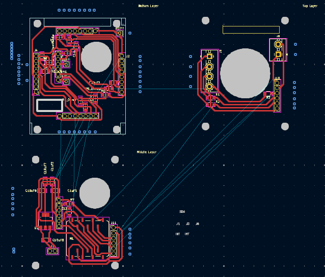
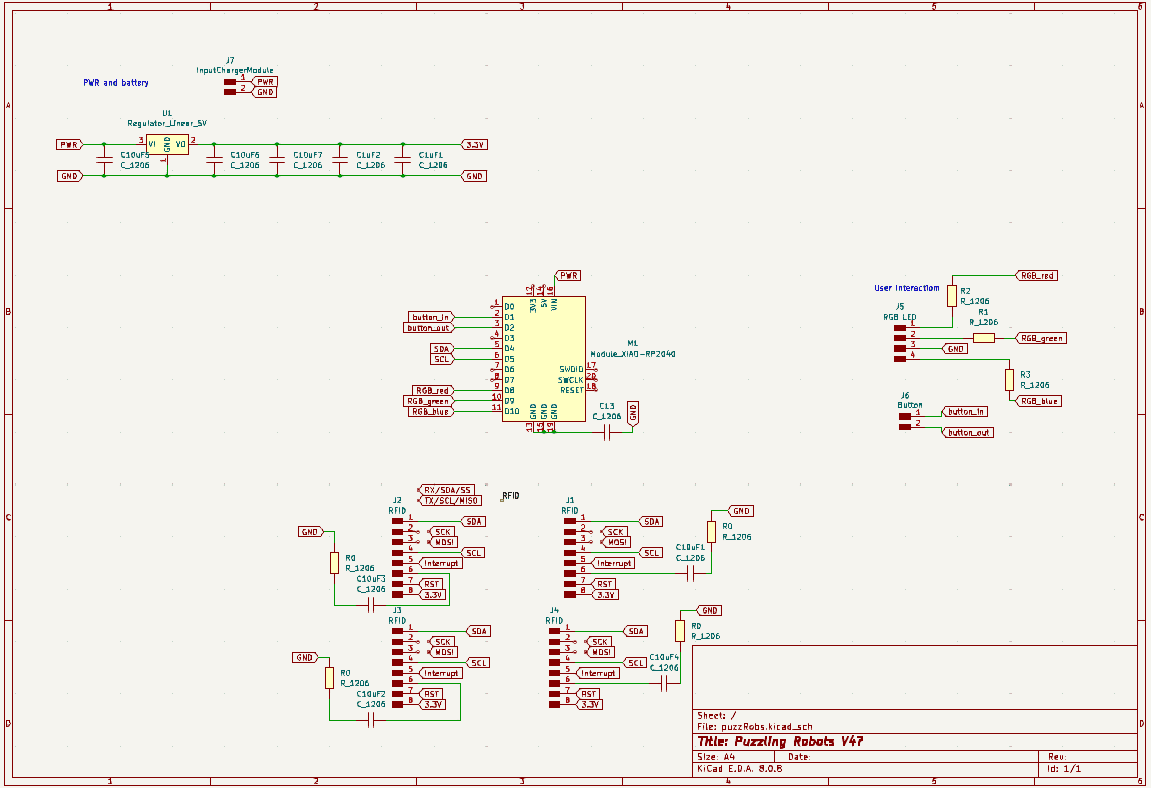
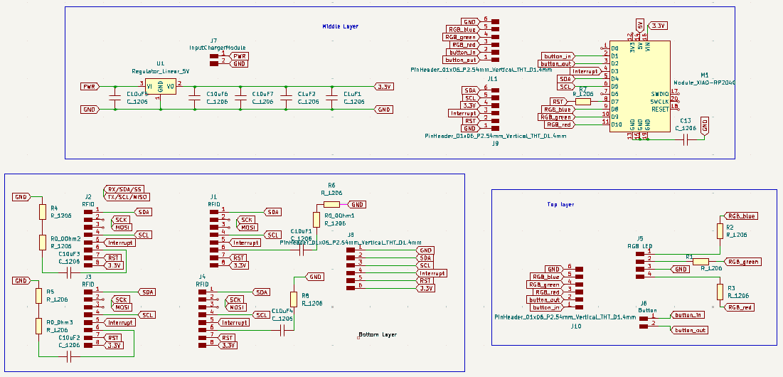
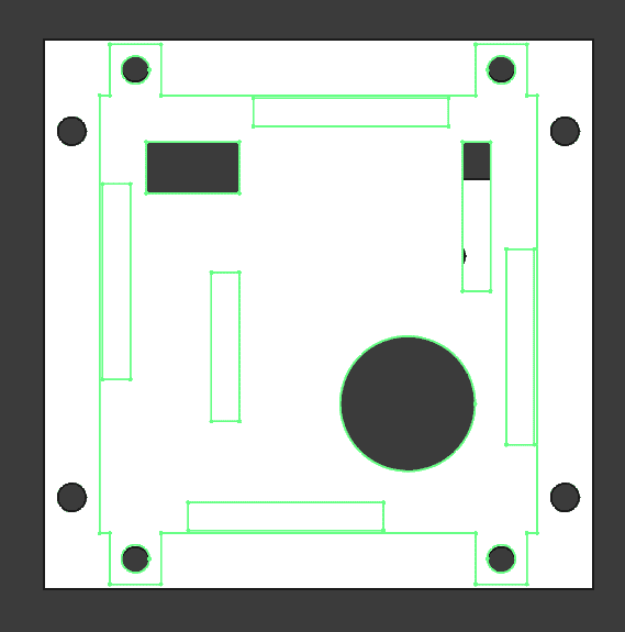
V4:
V4 general schematic and footprints puzzling robots and Inscape edit
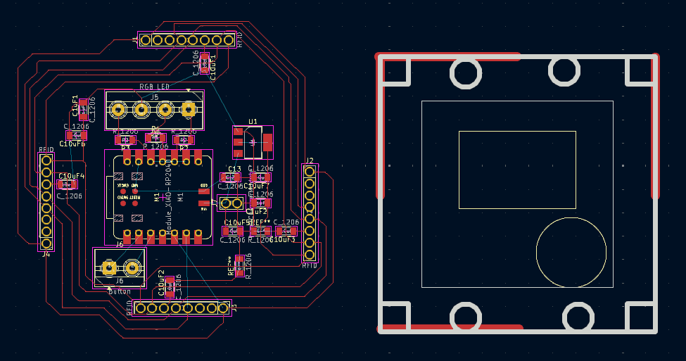
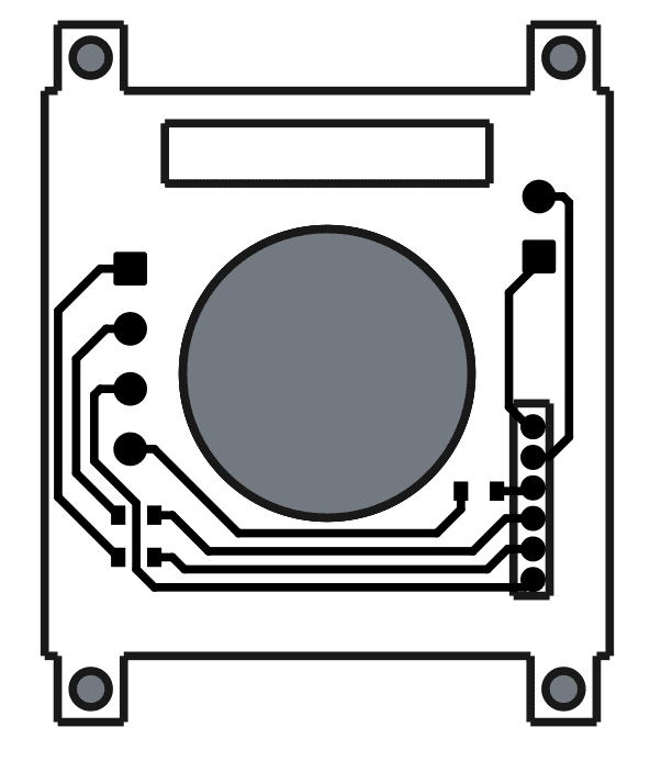
Production process. Left: freeCAD measuring based on bottom plate; Right: Fitting the traces into the freeCAD SVGLeft: The imported lines are not straight. I just hope it will work itself out in the production process;
Right: There was no fill from the imported FreeCAD svg, making it really hard to invert the colors. Fixed it by creating a new rectangle as a background.


