Submodules
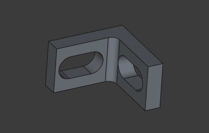
Charging slider
In order to comfortably connect each robot to its charging base in the box, I decided to make a slider that mechanically guides the robot into the right position:
Current status: V4 in progress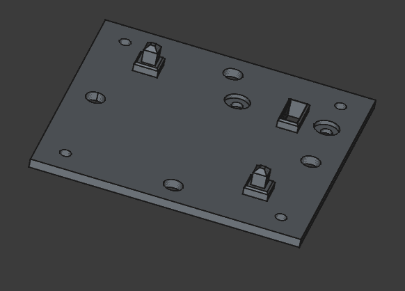

Download files:
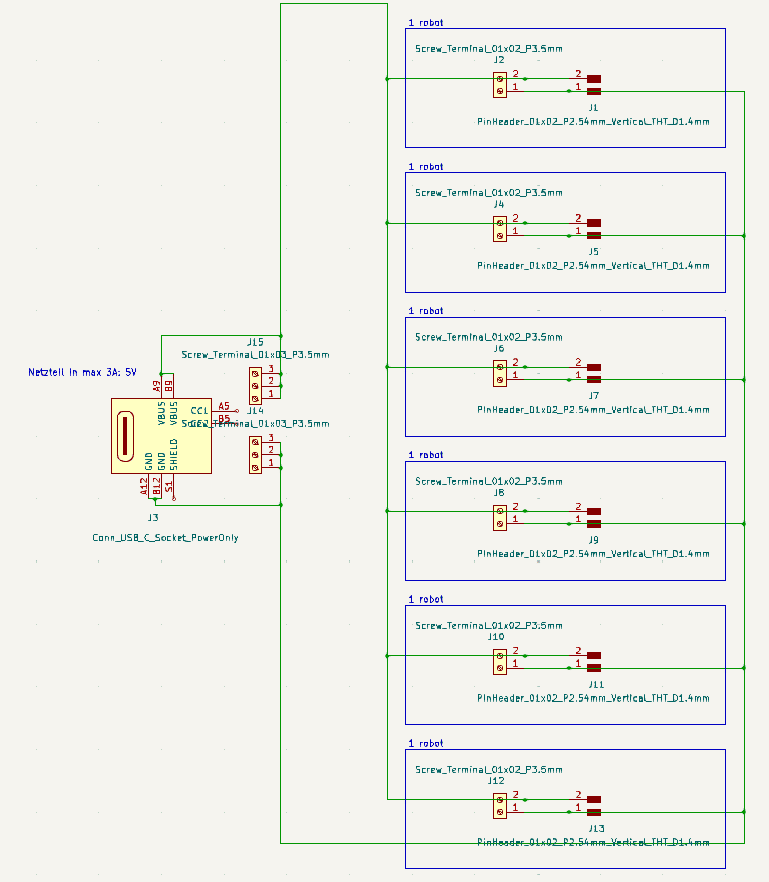
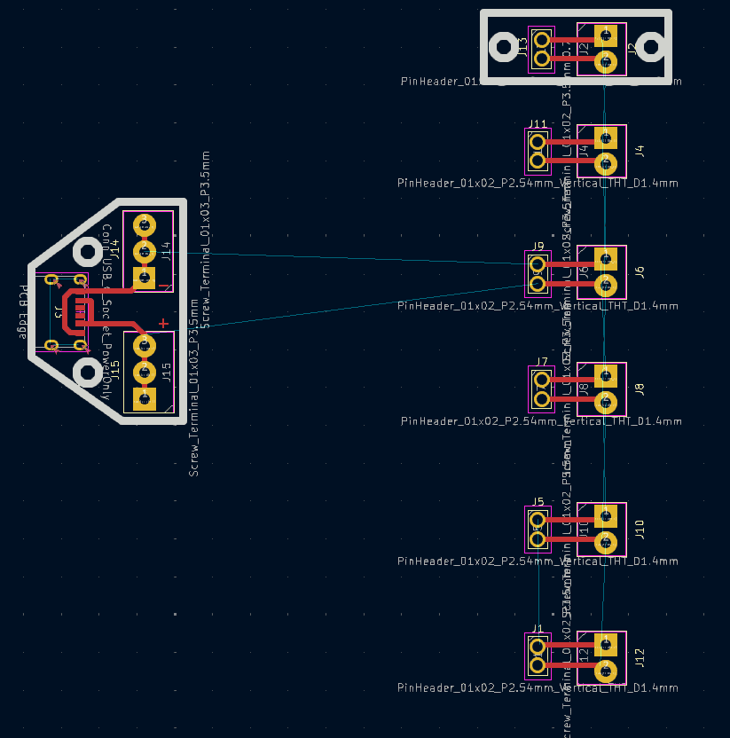
Power distribution system
Current status: V1
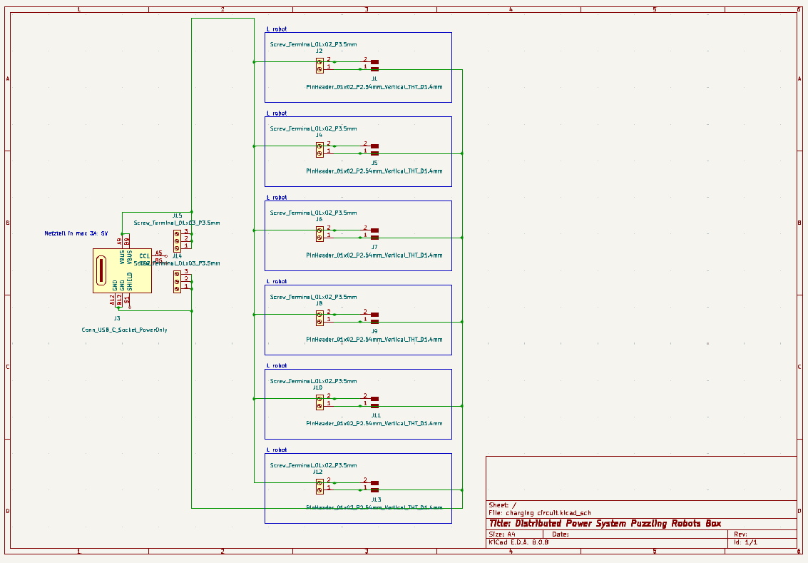
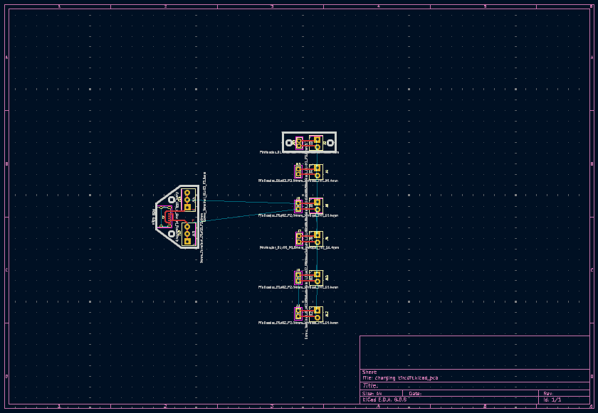
Download files:
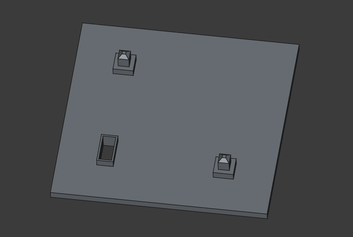
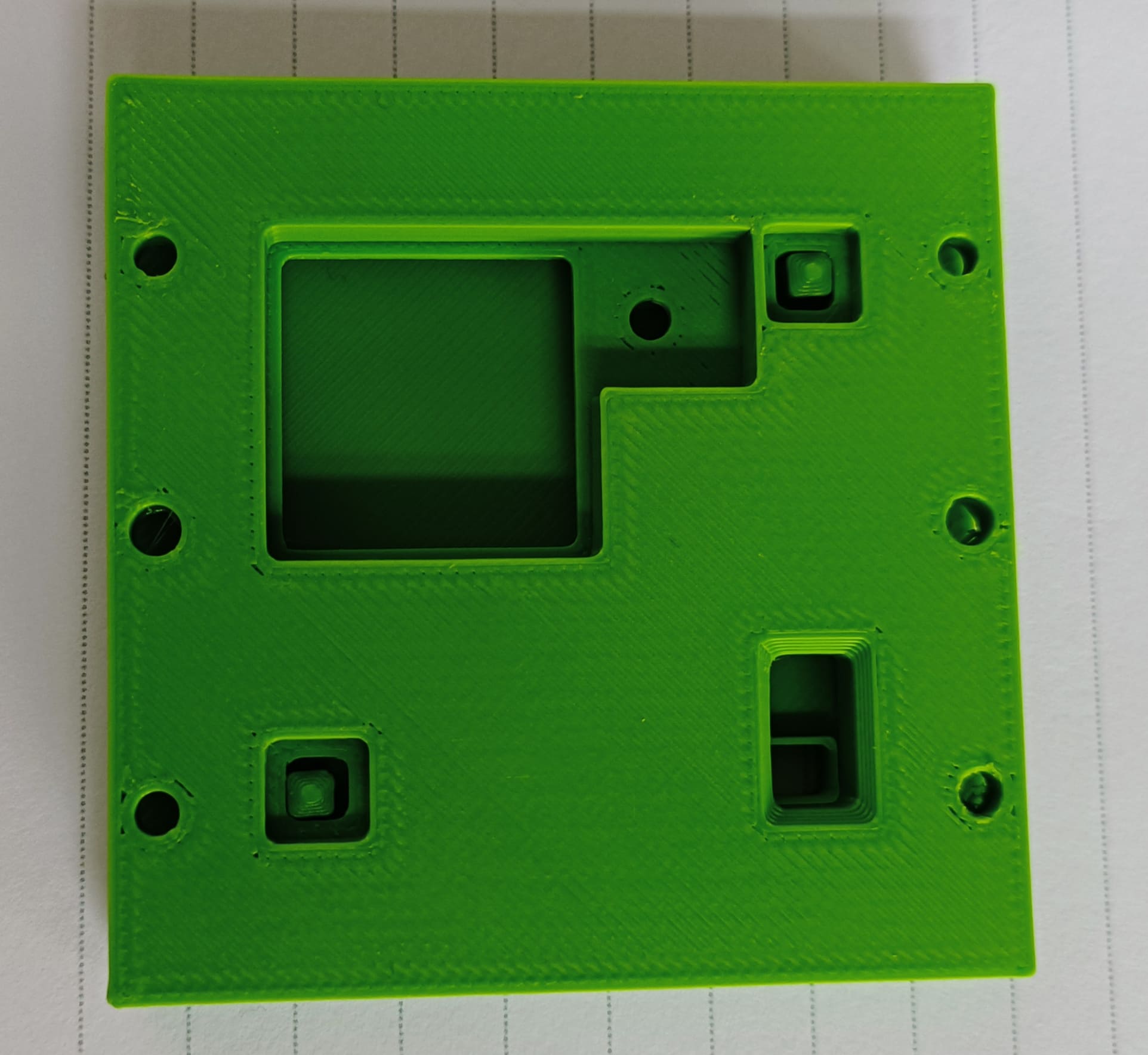
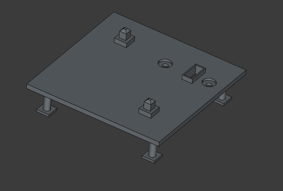
Box
Current status: V2
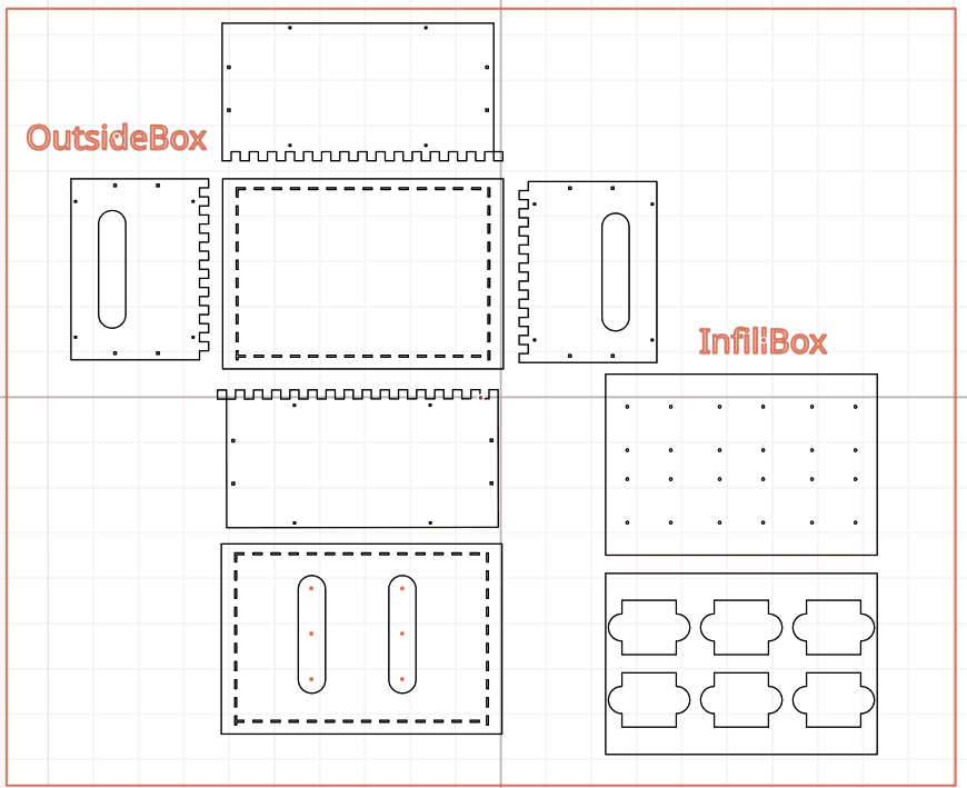
Download files:
Materials:
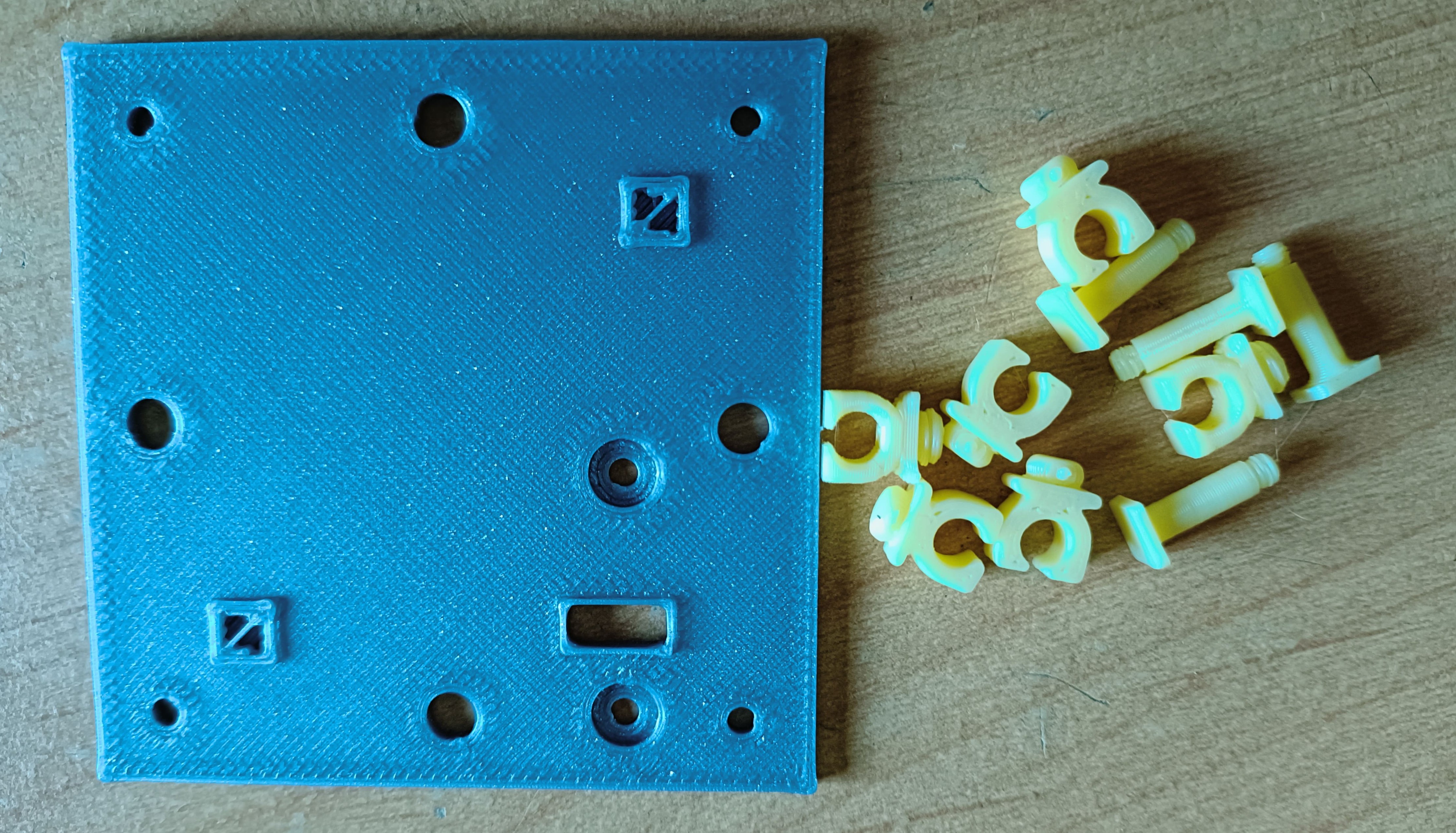
Box connector pieces
To connect the sides of the box together.
Current status: V1