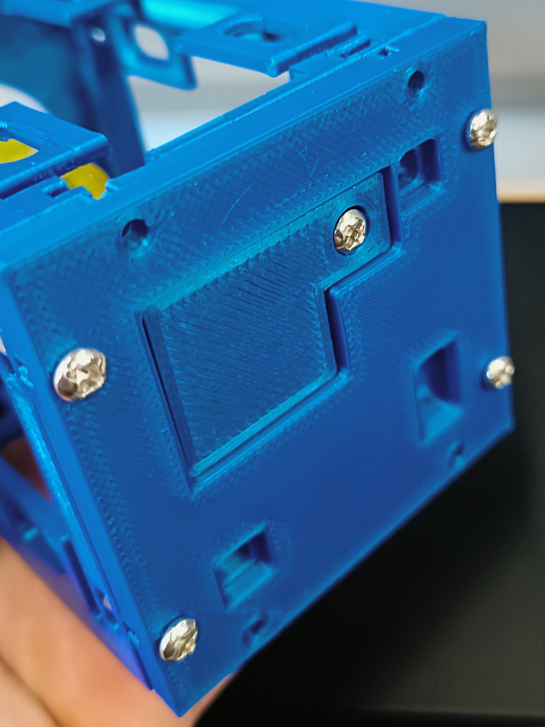
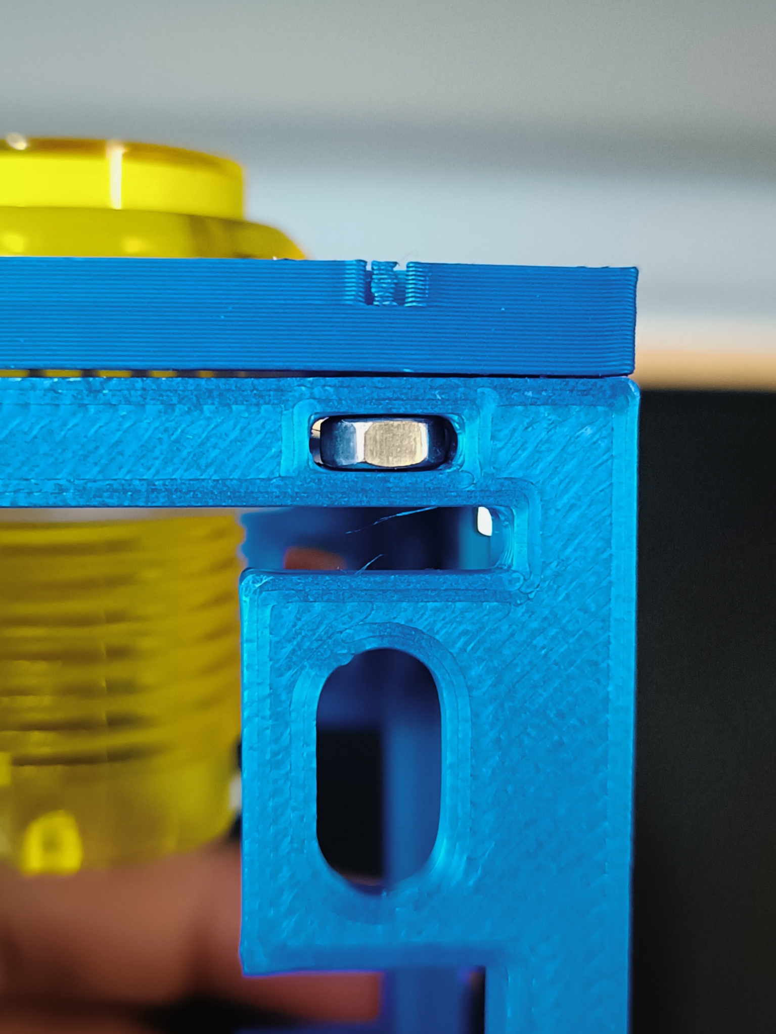
Slid in the nuts into the little slot and warm it up a bit to secure them
Connect the top and the bottom at the side that is longer on the outside using the screws. To combine the halfs turn one upside down
Mount the electronics
Note: All files and images are made in FreeCAD. Components printed on either the Prusa XL or Prusa MK4. Sliced in Prusa Slicer.
Roadmap
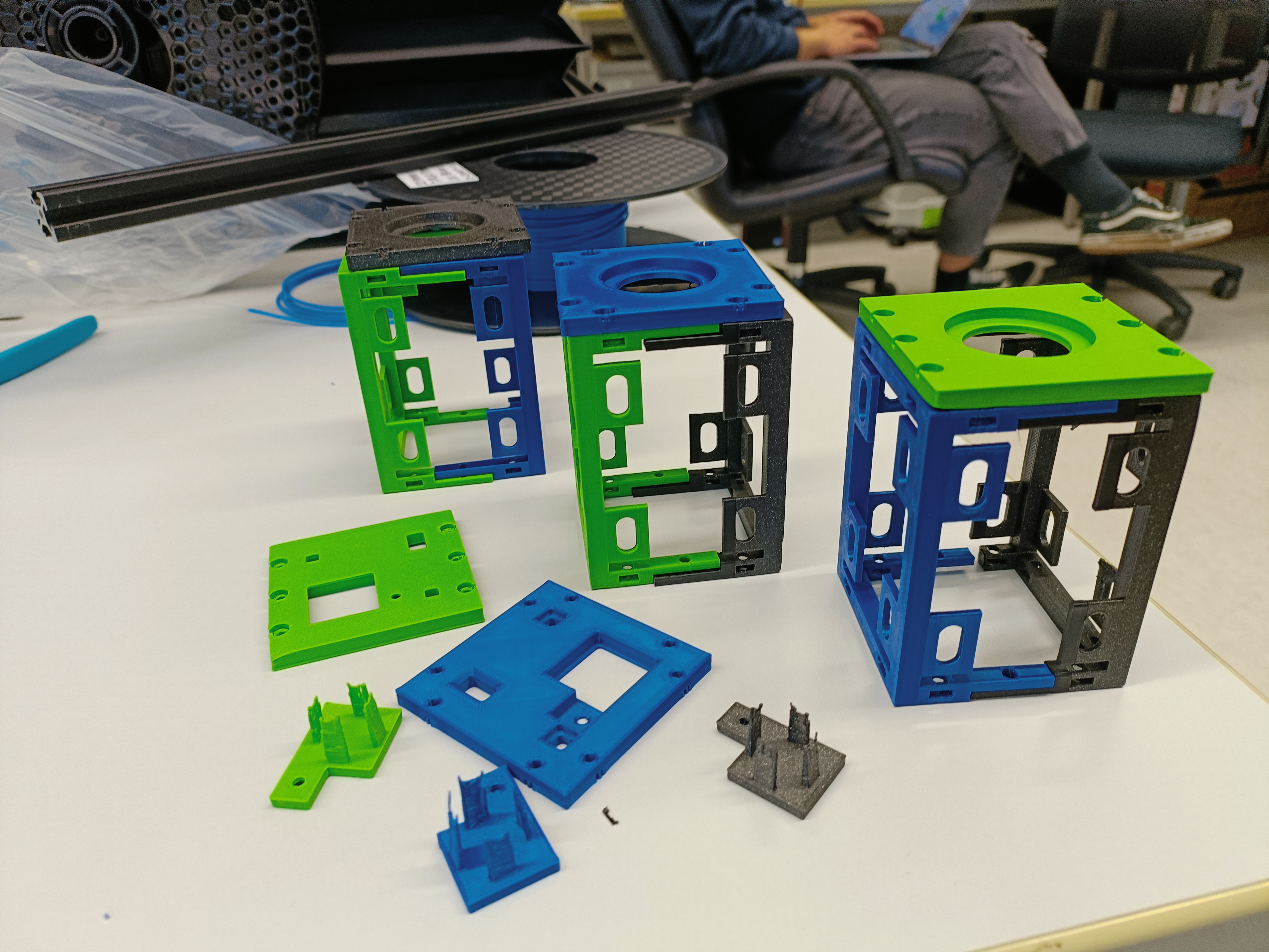
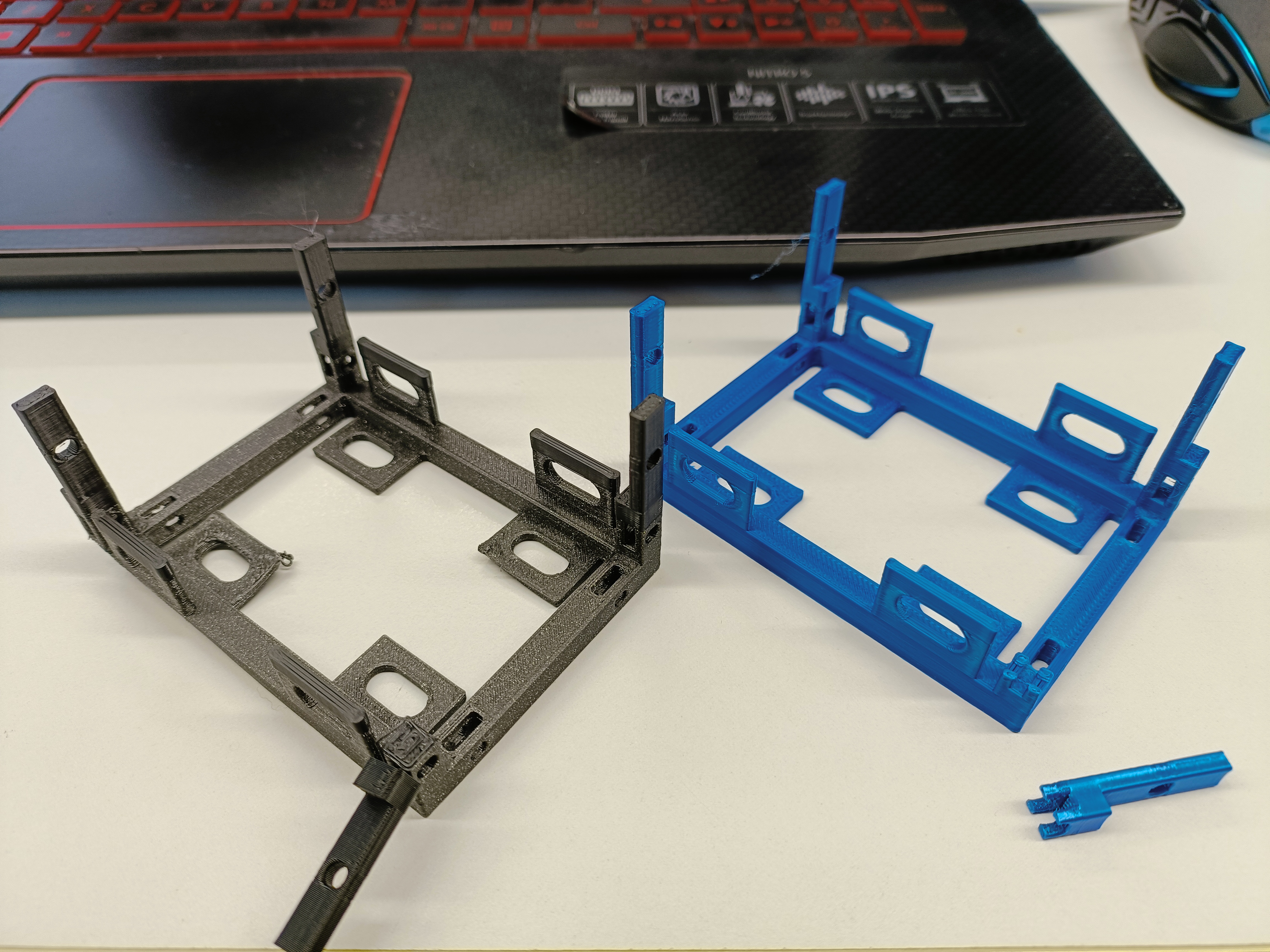
From left to right, oldest to newest: Comparison of the printed Versions.
From top to bottom: oldest to newest
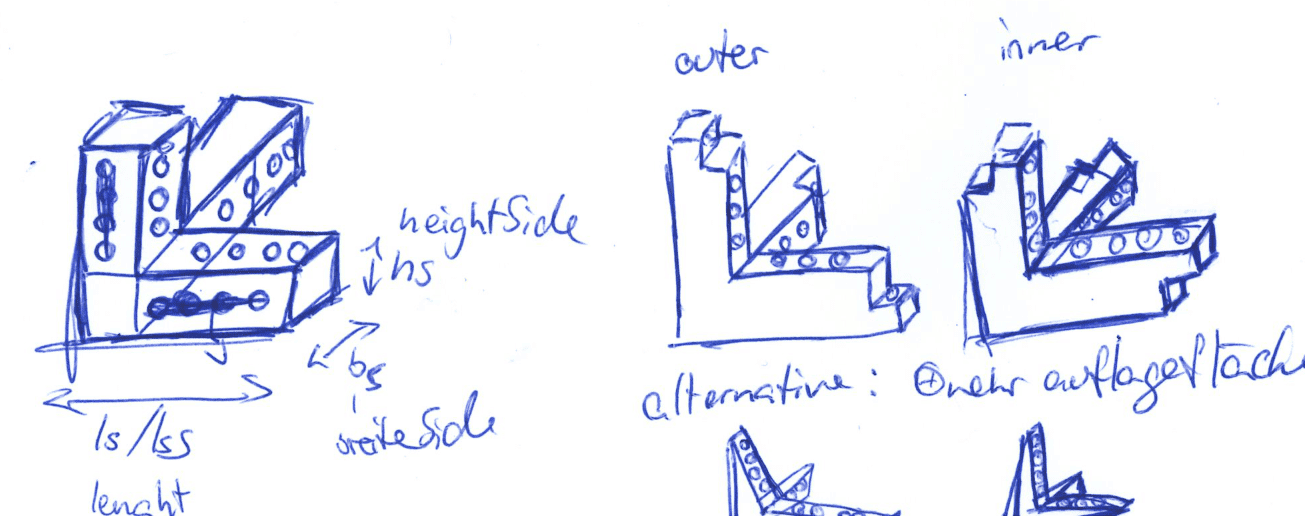
V1 Initial design:
Left: modular corner design; Right: initial sketch
After that there was a more detailed sketches and failed versions:
A better sketch of the corner 3D design
This approach works but required a lot of printed parts and many screws. In general, I was not quite happy with it.
V2 New design.
It now features:
Less separate components to print
A battery lid
A way to attach a button and RFID modules
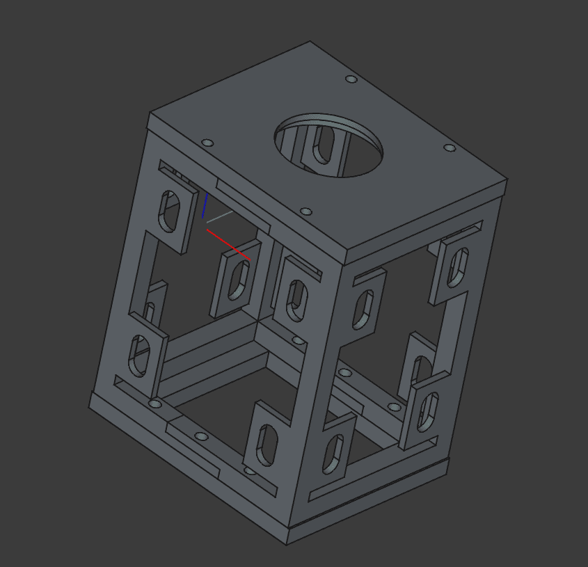
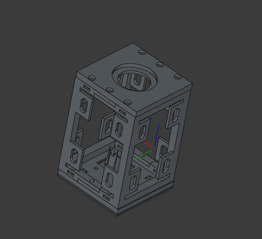
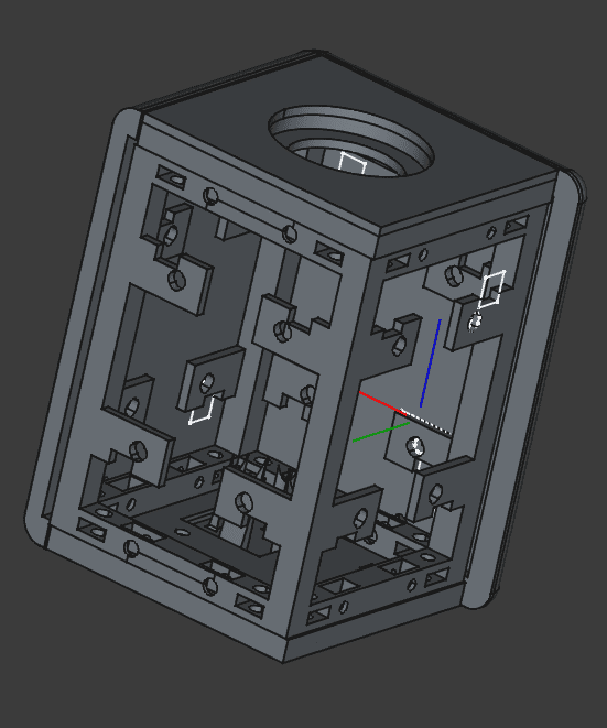
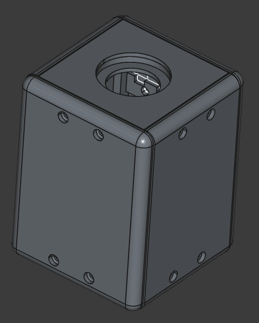
Assembly view of V5 puzzling Robot chassis
Test results:
Battery holder could be a bit smaller but fits in the battery and button.
Battery lid needs to be redesigned
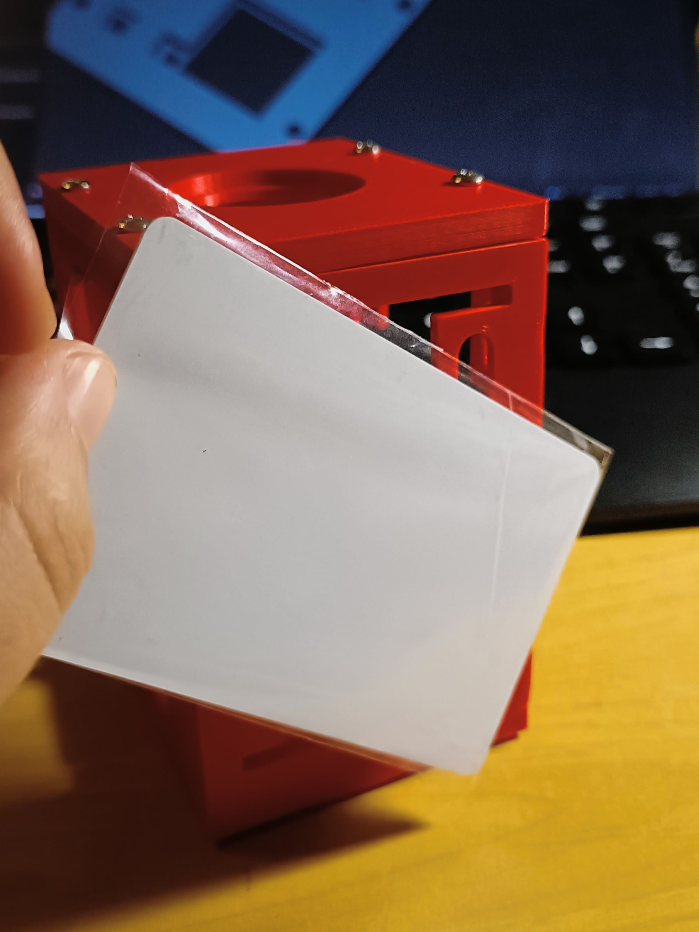
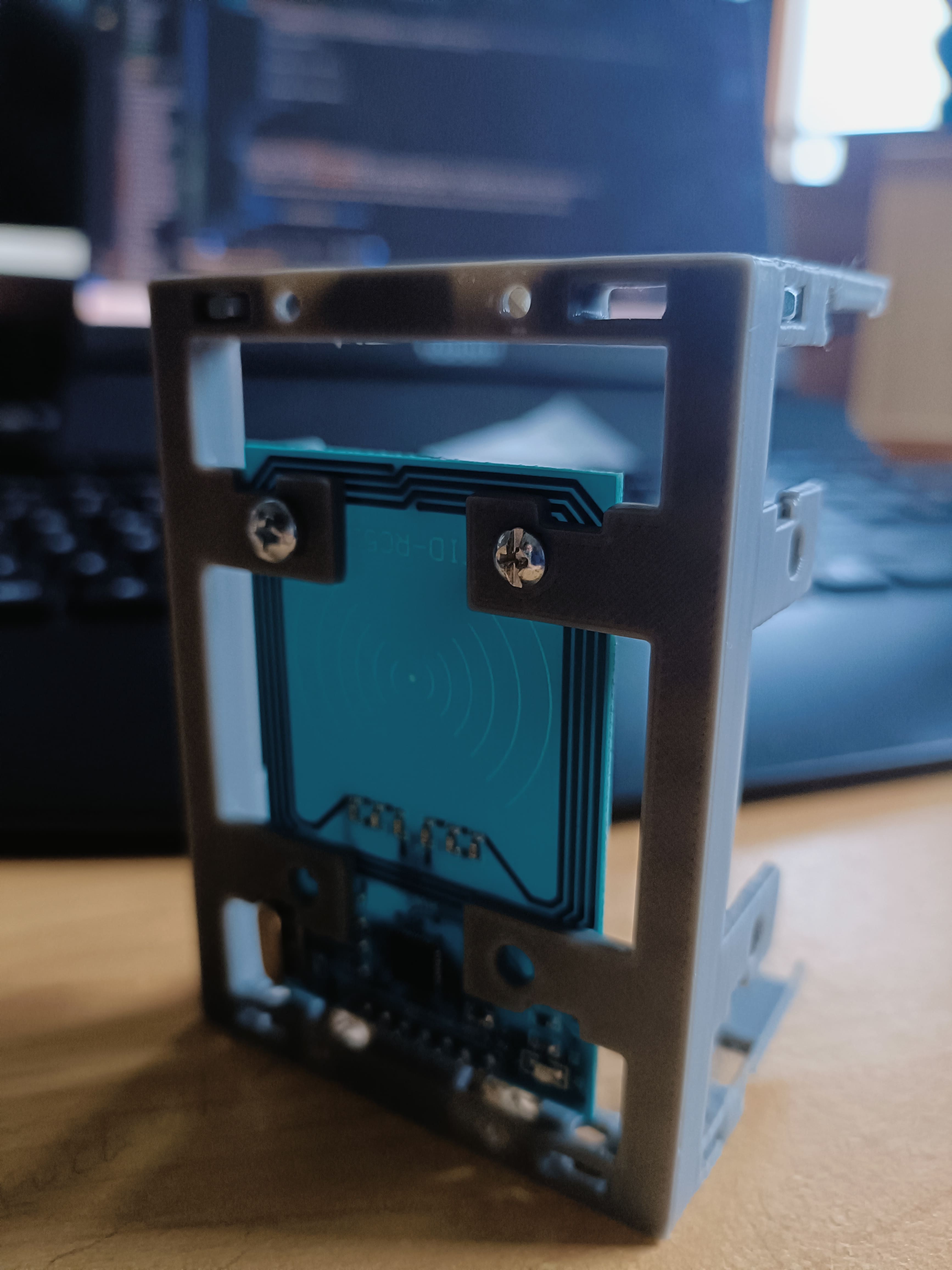
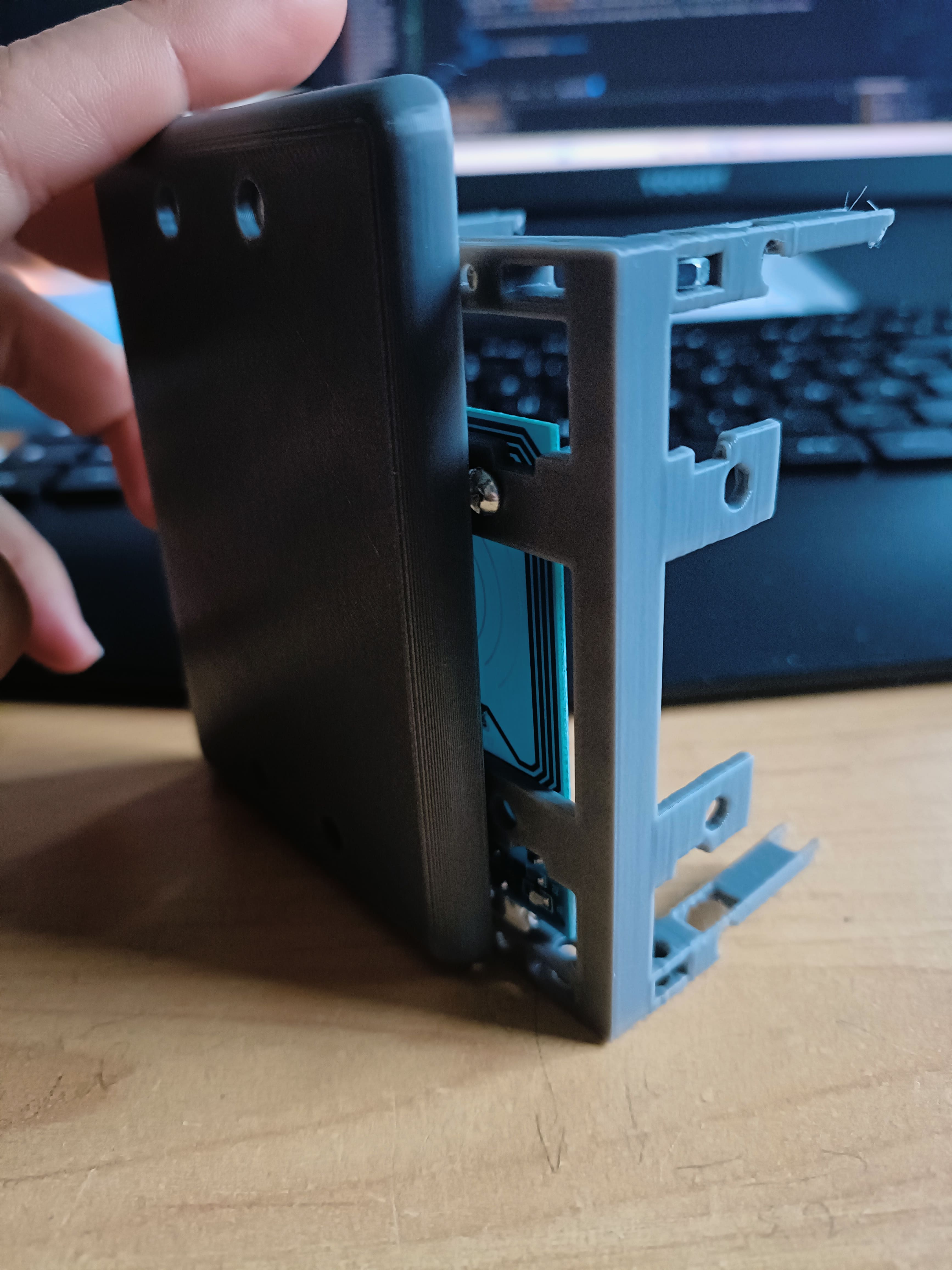
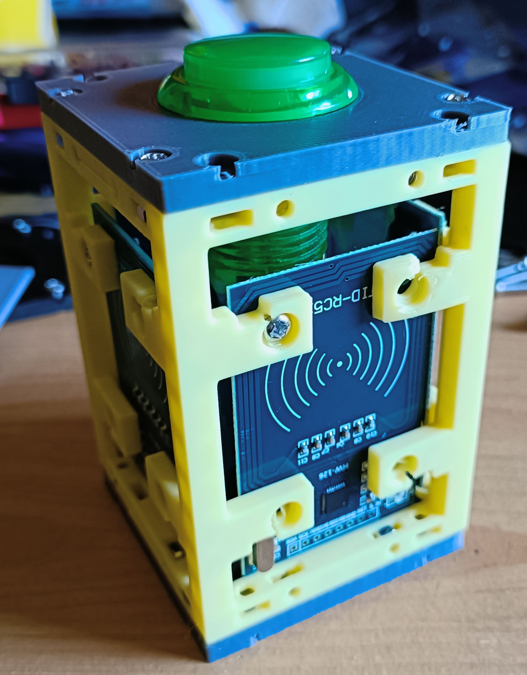
RFID module and card in comparison to the chassis. The RFID module does not quite fit smoothly but I'm happy with the size.
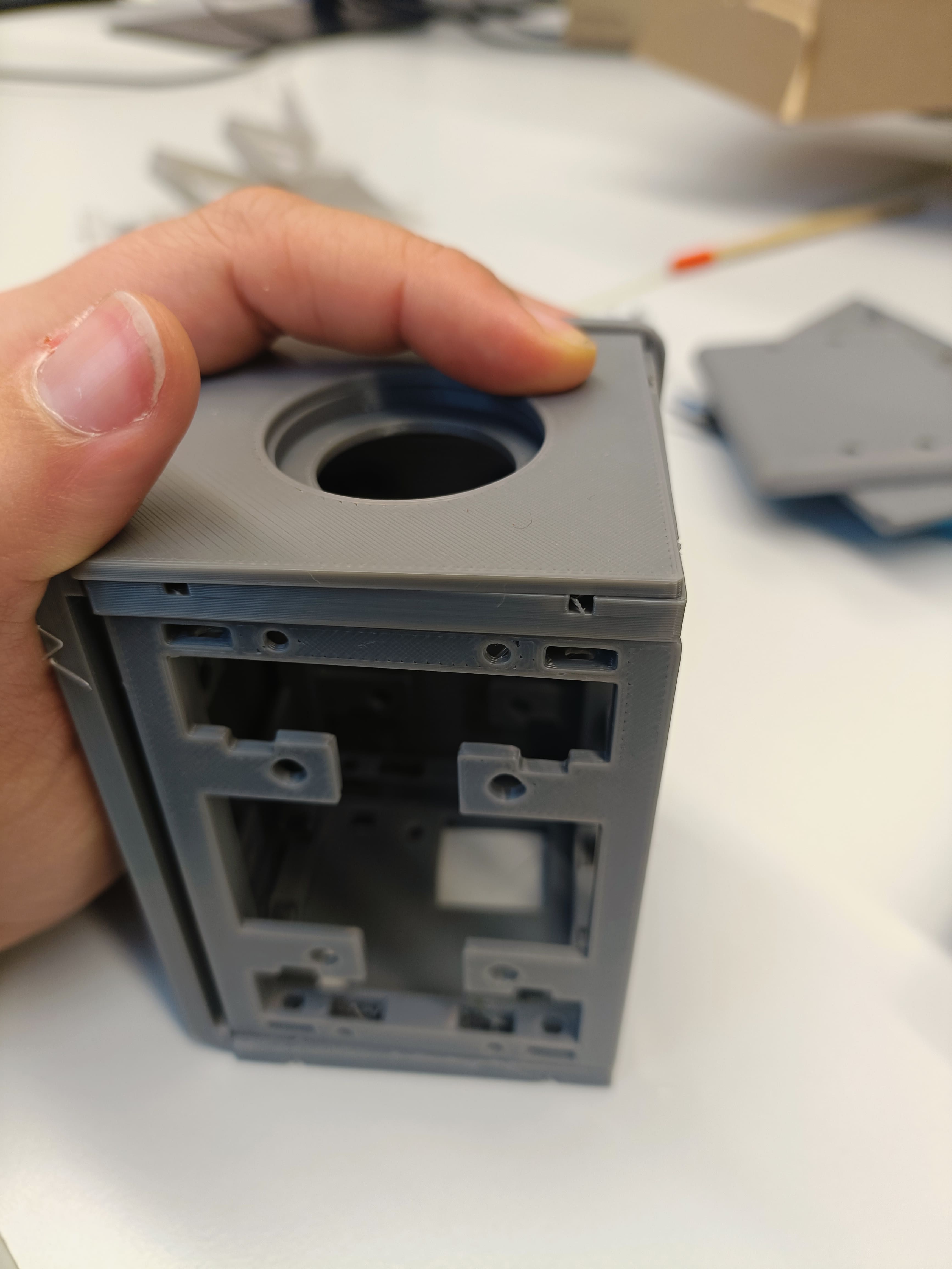
V3
Based on the test results, this design features:
Added a screw hole in the middle to attach electronics
The battery holder works nicely and the battery lid size is now fixed.
V4
Updated design based on the test results:
Changed the position of the screws for electronics to better fit the components in the circuit
Added more inlaid nut holes
Resizing charging slider connections
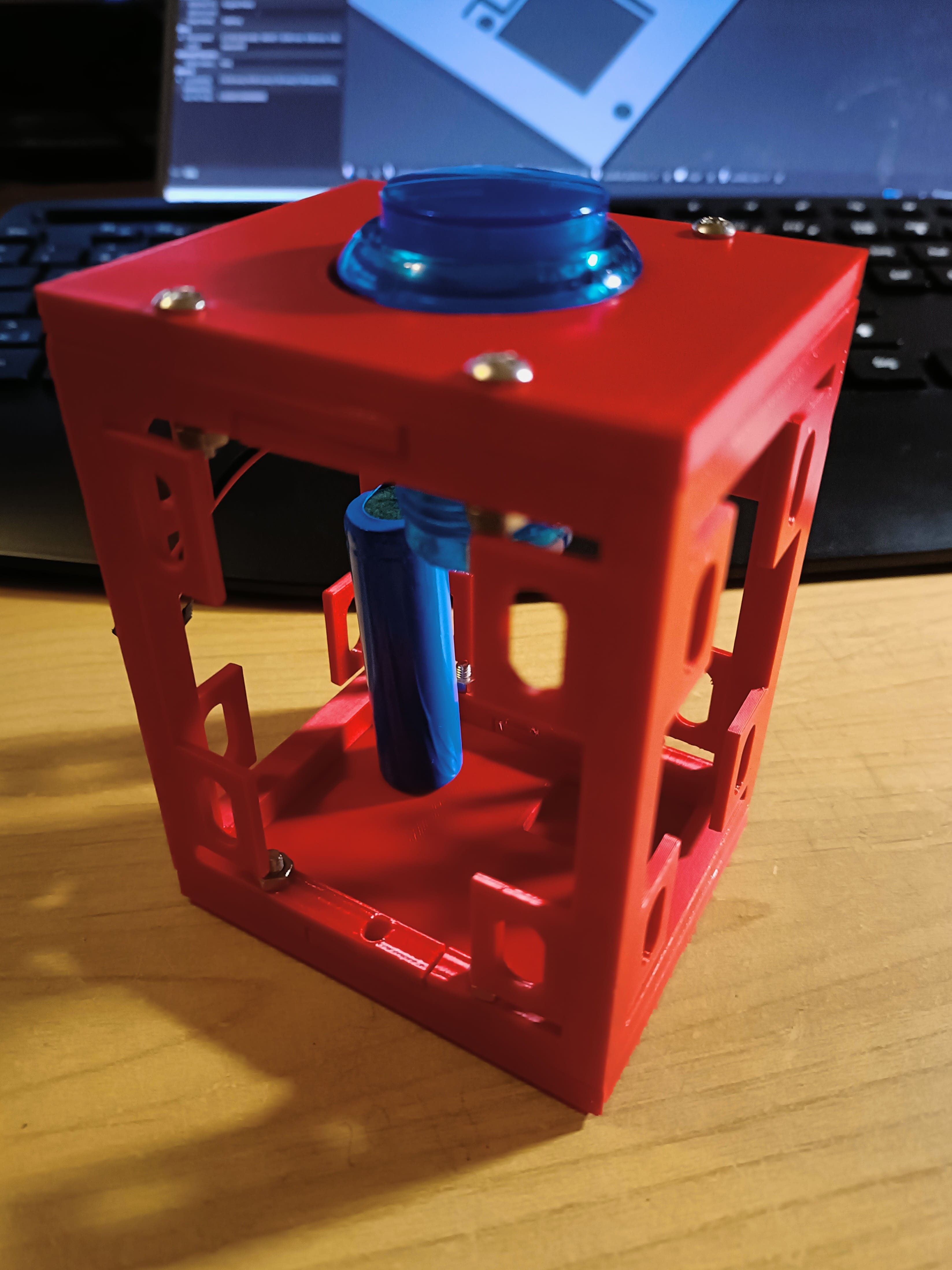
Assembly V4 design
To test it, I took it to a gathering with some friends with various backgrounds
(industrial mechanic, truck driver, pre-kindergarten educator, mechanic engineer, software developer, sales manager, electrical engineer,
children aged 4-8). This is their feedback (and some of my observations):
Mechanically sound design especially with the inlaid nuts. The only mechanical concern would be micro vibrations
that might loosen the screws. Can be fixed with securing nuts or anti vibration spacers.
The sides should be closed.
Children are also going to use however, not only the intended way. Make sure it is solid enough that they can be stacked
and stepped on.
The button is really solid. Someone was always pressing it throughout the night.
Make all corrosive parts easily accessible to replace them in case of failure.
Round the corners to avoid injuries!!!!
Use only little colors to make them more easy to distinguish for young children and elderly.
The 3D print is quite sturdy - during the hole trip it did not take any damage, not even a scratch.
Suggested game options:
Picture and Voice - Visual speech training
Use it as a remember-what-I-was-about-to-say-or-do button
Who can press the button the most within a certain time frame
Make (pixelart) puzzles according to what the card shows
Create a path between to buttons. Depending on the color of the light, each side of the cube is either open
and can make a path or closed to block that side (to make it more difficult: buttons change sides at a certain time)
Based on the last idea: maybe even electrical circuits?
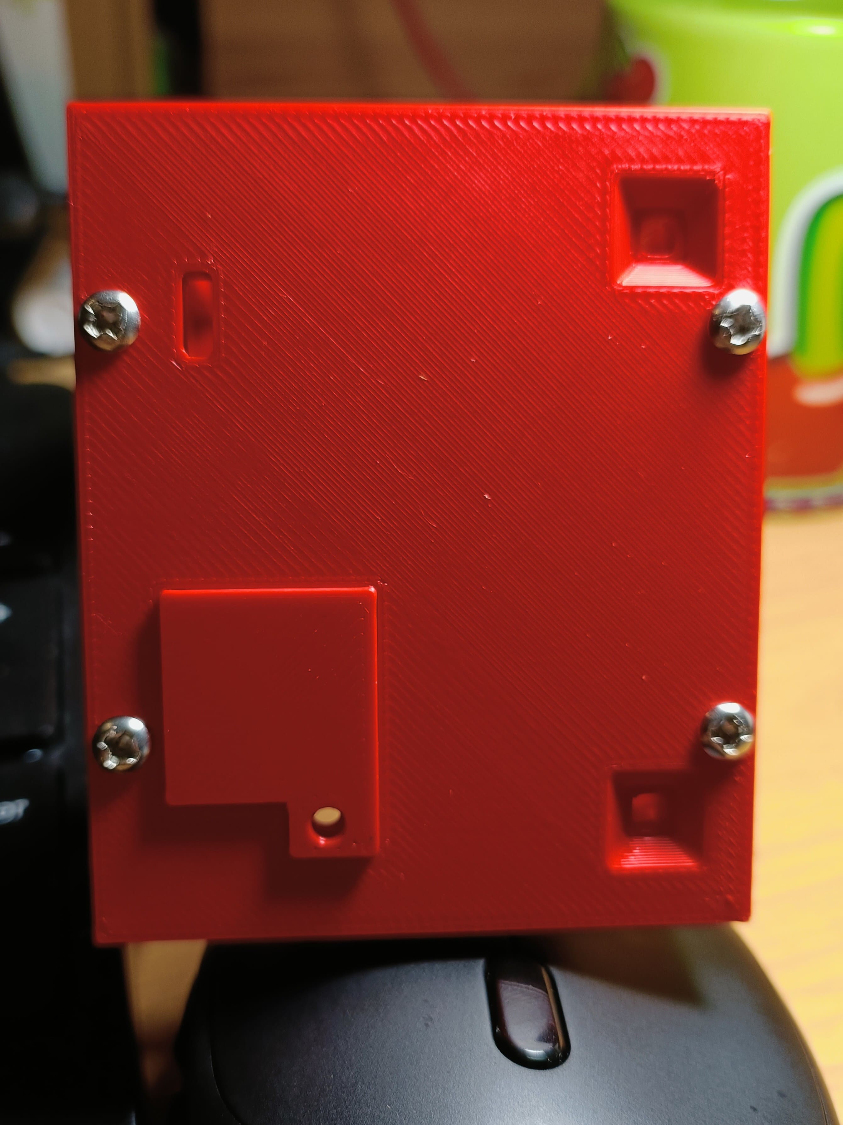
The design is still fully compatible with the previous designs.Left: fixed the battery lid screw problem. Right: inlaid nutsIndividually the halfs are frail: the black one broke where I had to exchange the filament,
the blue one bc I applied to much force in parallel to the printing direction.
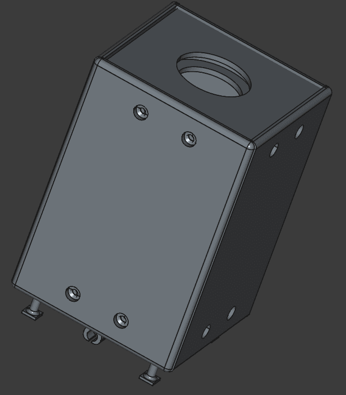
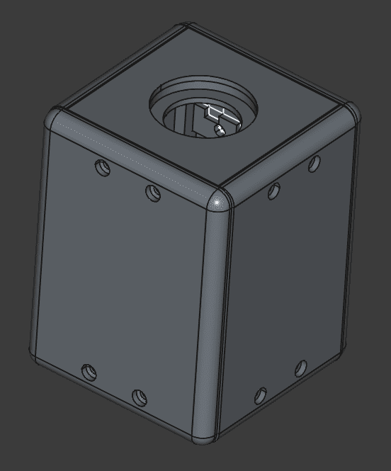
V5V5 of chassis
The new design features the suggestions and fixes some issues of the previous model:
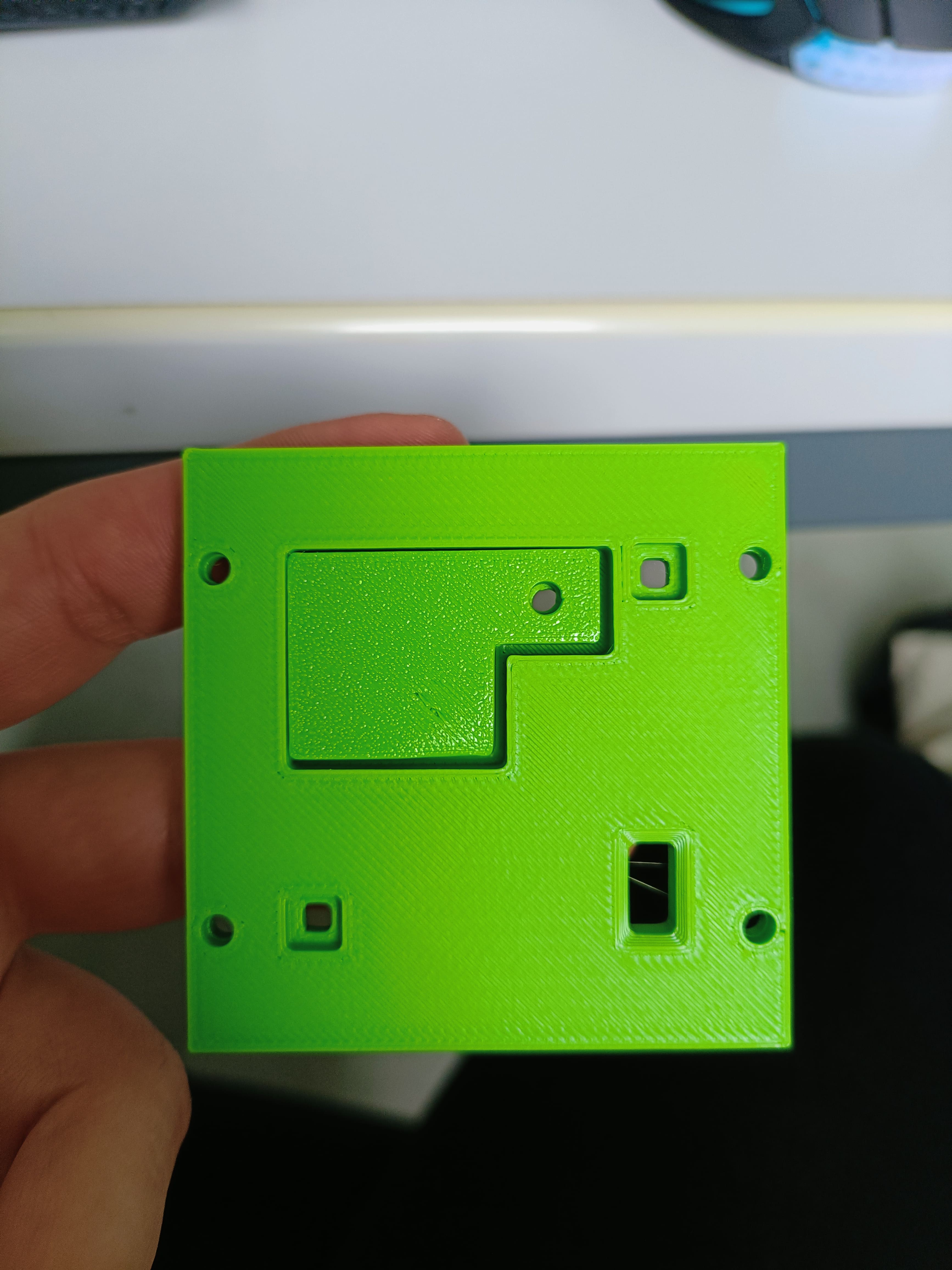
Adding side plates
Added a top top plate to hide the screws
Rounded the corners
Changed the direction of the screw outs from the bottom
Adapted the sizing of the first few inlaid nut holes
Changed the shape of the RFID holes allowing the module itself and the screws to be attached easier
Test results:
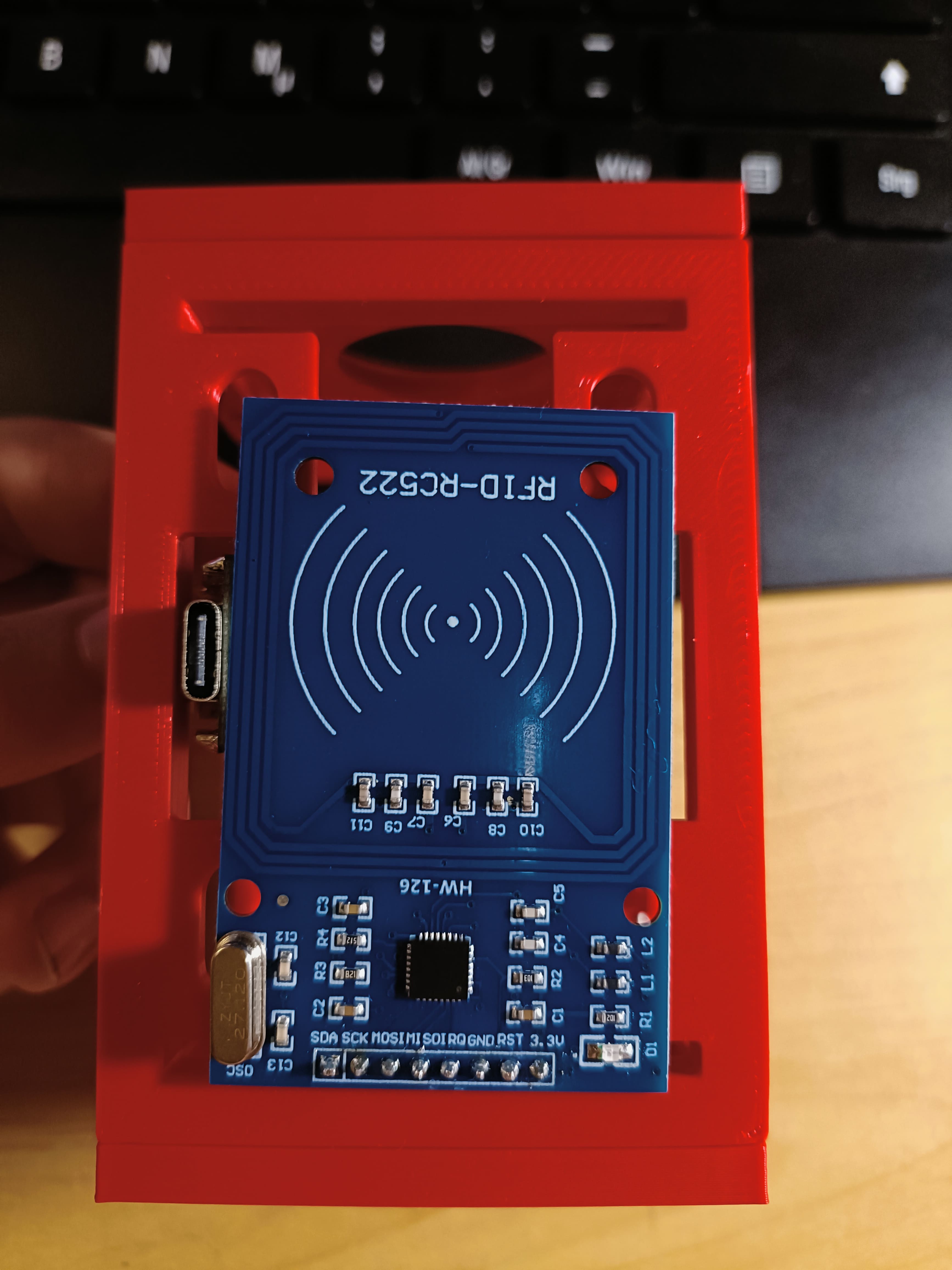
Left: RFID module fits quite neatly; Right: sizes fit well.Stuff that can be improved: Left: the hiding the screw plate has a lot of tolerance;
Right: some of the holes for the inlaid nuts are way too big and the side plates too thick.
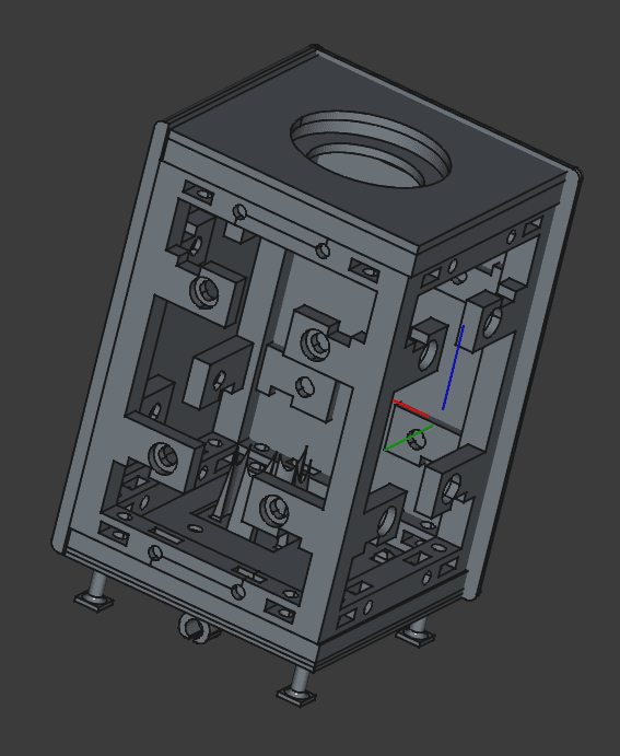
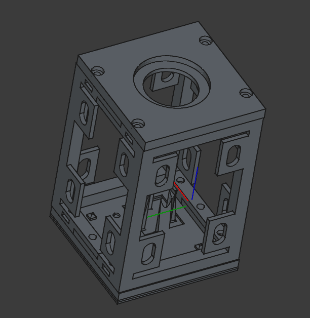
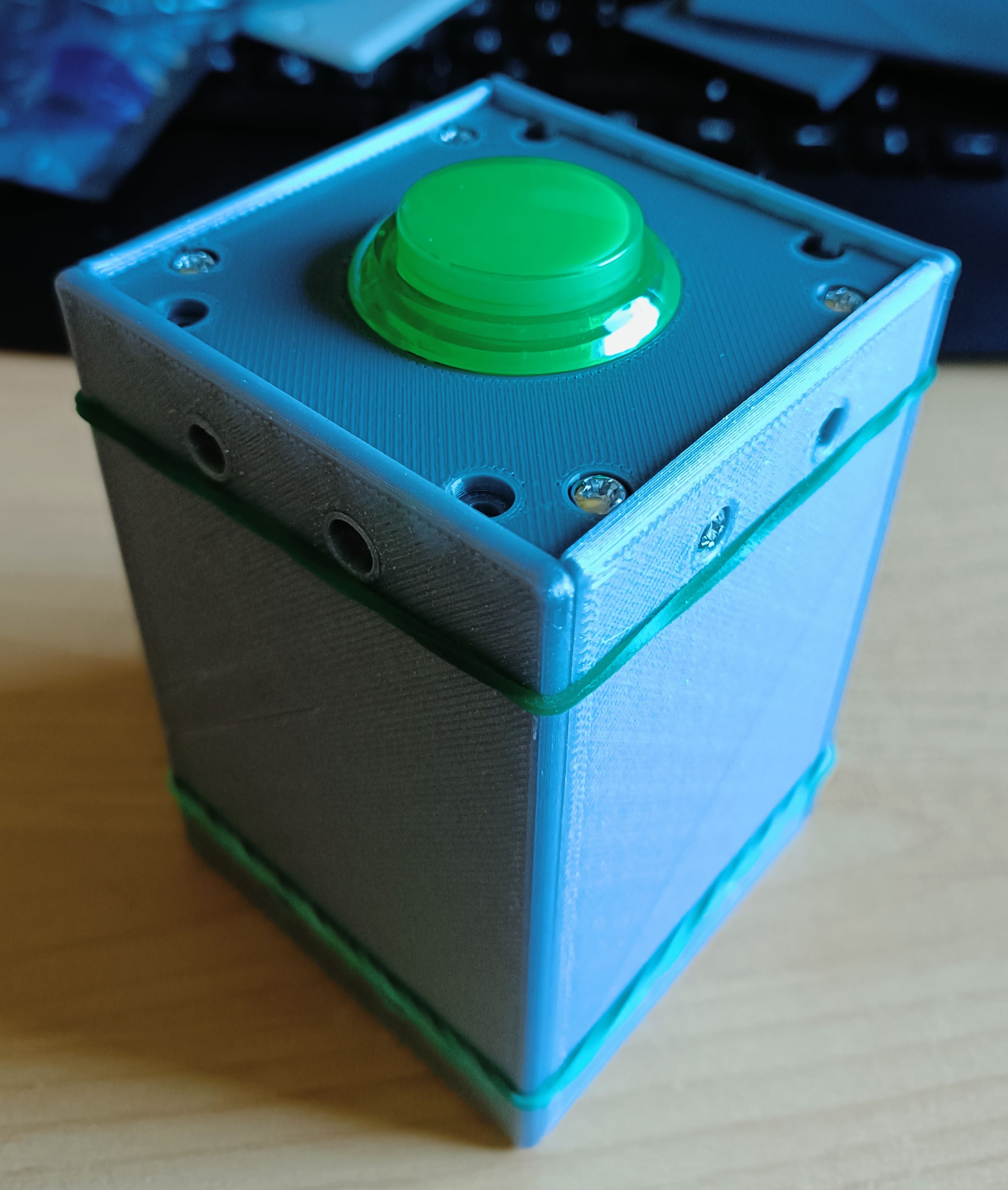
V6V6 chassis complete with charging slider in FreeCAD
Updates:
Fixed the issues in the last model
Inlaid the RFID modules
Flattened the outer shell to print considerably faster with less waste and no supports
All the little add-ons underneath the charging slicer can now be screwed on instead of printing with supports
Test results:
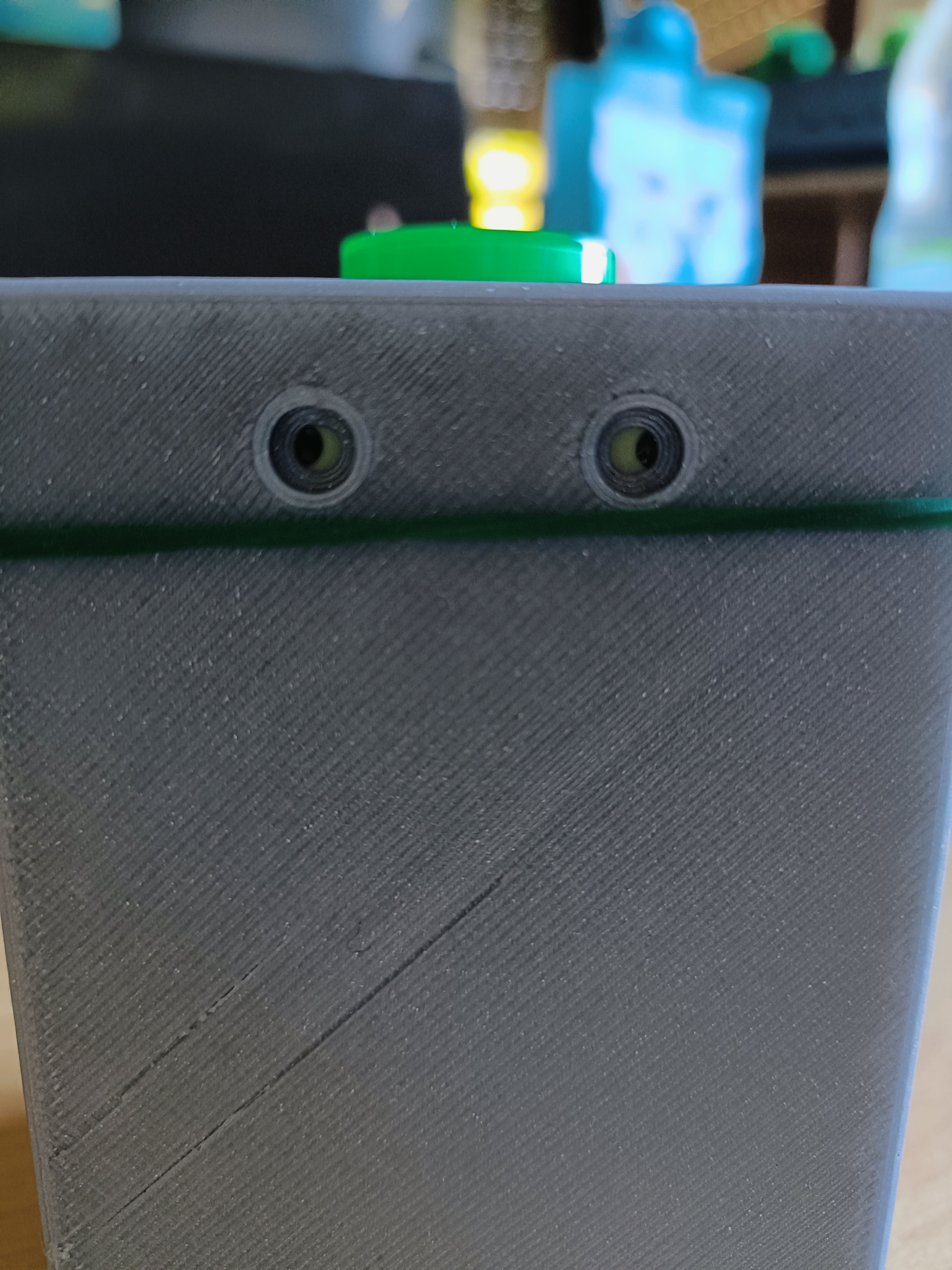
Printed and assembled V6 chassisIn the long side plate the holes are not quite aligned
While mounting the RFID modules, I noticed it is quite annoying to do so. It makes sense to design and 3D print a tool to help with it.
V7
Updates:
Fix securing holes on big side plate
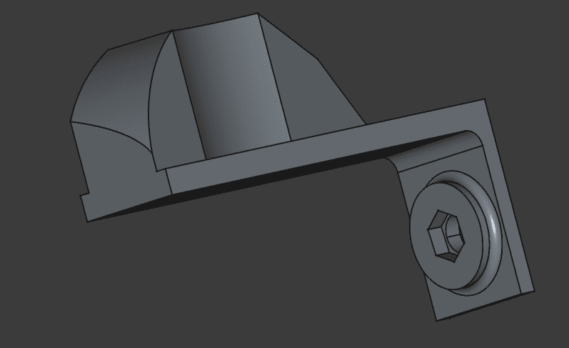
Design tool to hold nuts while attaching rfid modules
Remove the threaded inserts from top and bottom pieces
Figure out a way that the button is unable to screw out
Top an bottom plates could be thinner -> adjust size of side plates