Tasks:
- Group assignment:
- Measure the power consumption of an output device
- Individual assignment:
- Add an output device to a microcontroller board you've designed, and program it to do something
More issues in PCB Design
Kerala's gerber2png sometimes does not allow download
Tried the other fab program to create images from gerbers, but I have no idea how to use it. Therefore, I went back to inscape. BUT the workflow is quite annoying: in Kicad plot as pdf. Import in Inscape. Manually change the background. Export as png. Process can be shortened and less prone to errors if we can avoid the manual background change.
Alternatives to inverting images
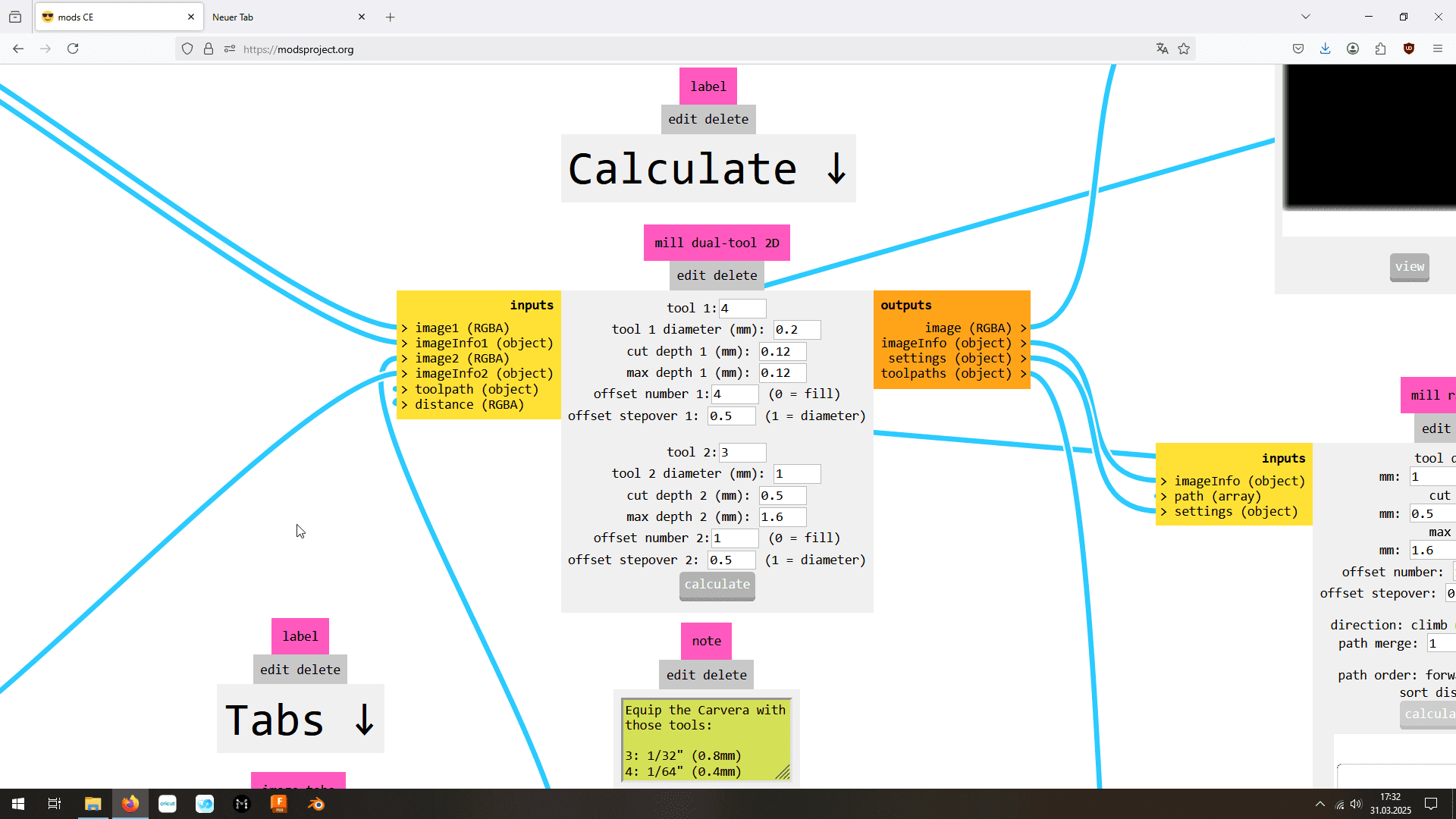
Solution 1: Inverting button in Mods CE: sometimes the images are not read correctly and so can not be inverted.
Solution 2: Inverting in Inscape. Sometimes does not work. For some reason traces sometimes will not change colors.
Solution 3: Inverting on this website. Works smoothly but crops the image to minimal size, effectively changing the distance from the margin. Mods CE does not allow to change the offset of the pictures, therefore the milled PCB would be useless. Second more relevant problem: The inversion is not precise!
Solution 4: back to Kicad. Are there ways to simplify the work flow through more efficient exporting? In Inscape, are there faster ways to get the required settings?
- Kicad: After drawing the outer line in the Edge.Cuts layer inside the PCB window, double click on it.
- Kicad: This will pop up an new field where the properties can be changed. Change 'line width' to '1' and 'type' to 'solid'.
'solid is especially important because otherwise the margin will not show up the way we want it to.
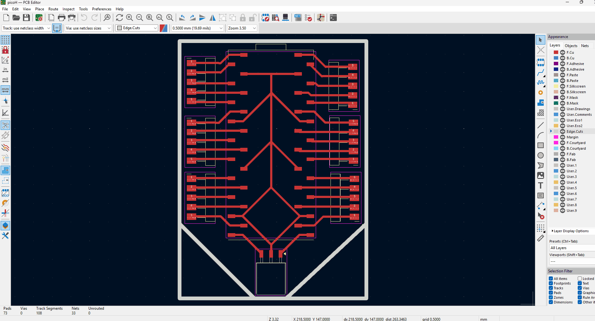
Result in Kicad PCB (obv. your schematic will look different) - Kicad: 'File'->'Plot'. A new window will pop up. Select the desired address with a click on the stereotypical folders button. Right next to that field, the plot type can be changed. Select either 'svg' od 'pdf' format.
- Inscape: In red menu hit import pdf/ svg. 'Path'->'Trace Bitmap'->'Apply' to be able to change the color of the traces themselves.
- Inscape: change the color of the traces by going to the blue menu on the right 'Fill and Stroke' and change the colors to pure white (000000ff) of both the margin and the fill.
- Inscape: Draw a rectangle using the green menu on the left side. If it is not visible it means that the margin and fill are the same color as your page background. If that is the case change it's color to a visible using the method mentioned before. This rectangle should be pure black (FFFFFFff in both margin and fill!).
- Inscape: Change the layer order by dragging the rectangle (short: rect) in the blue 'Layers and Objects' menu to the bottom. It might help to close the dropdown menu of the path. This step can be avoided id the rectangle is drawn before importing the images from Kicad but I also always forget.
- Inscape: Drag the edge cut picture to the rectangle. Make the rectangle the same size taking advantage of the magnet fit property of Inscape.
- Inscape: Drag both the margin and rectangle to the traces (hopefully you have not lost it yet). Align the black rectangle in a way that you want to have the PCB.
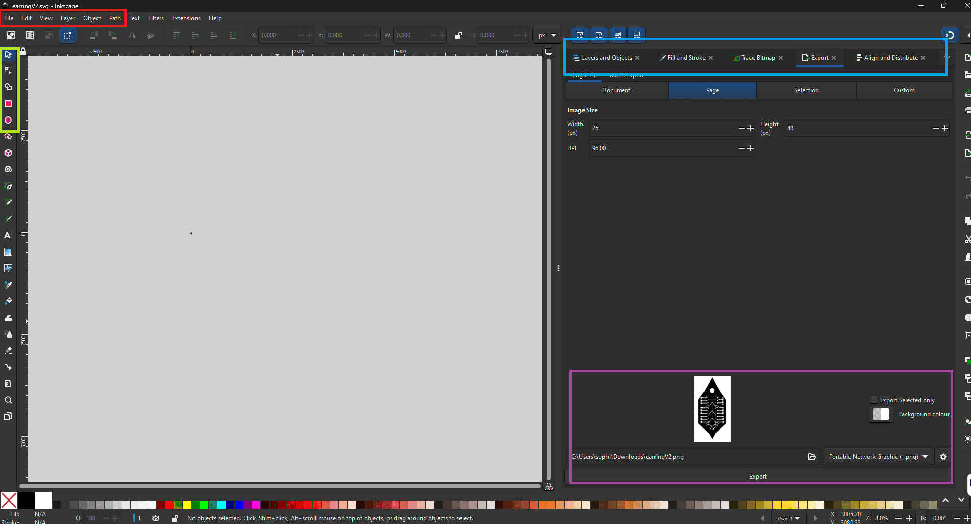
- Inscape: Select the rectangle and all traces and go to the 'Export' in the blue menu. Change the background type to pure black, select the location to export to and for the format 'png', and click 'Export' in the purple menu on the bottom.
- Inscape: Select the margin and export that one in the same way.
PCB broke
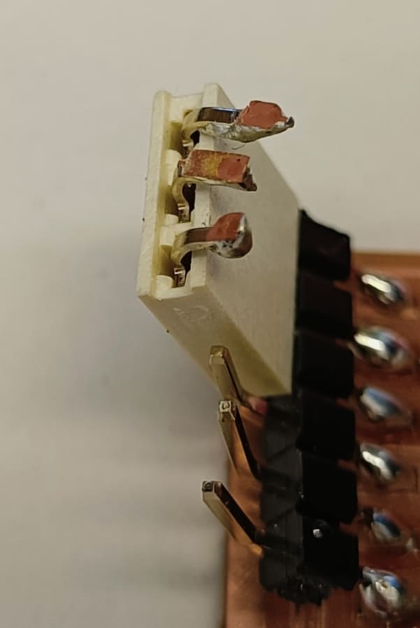
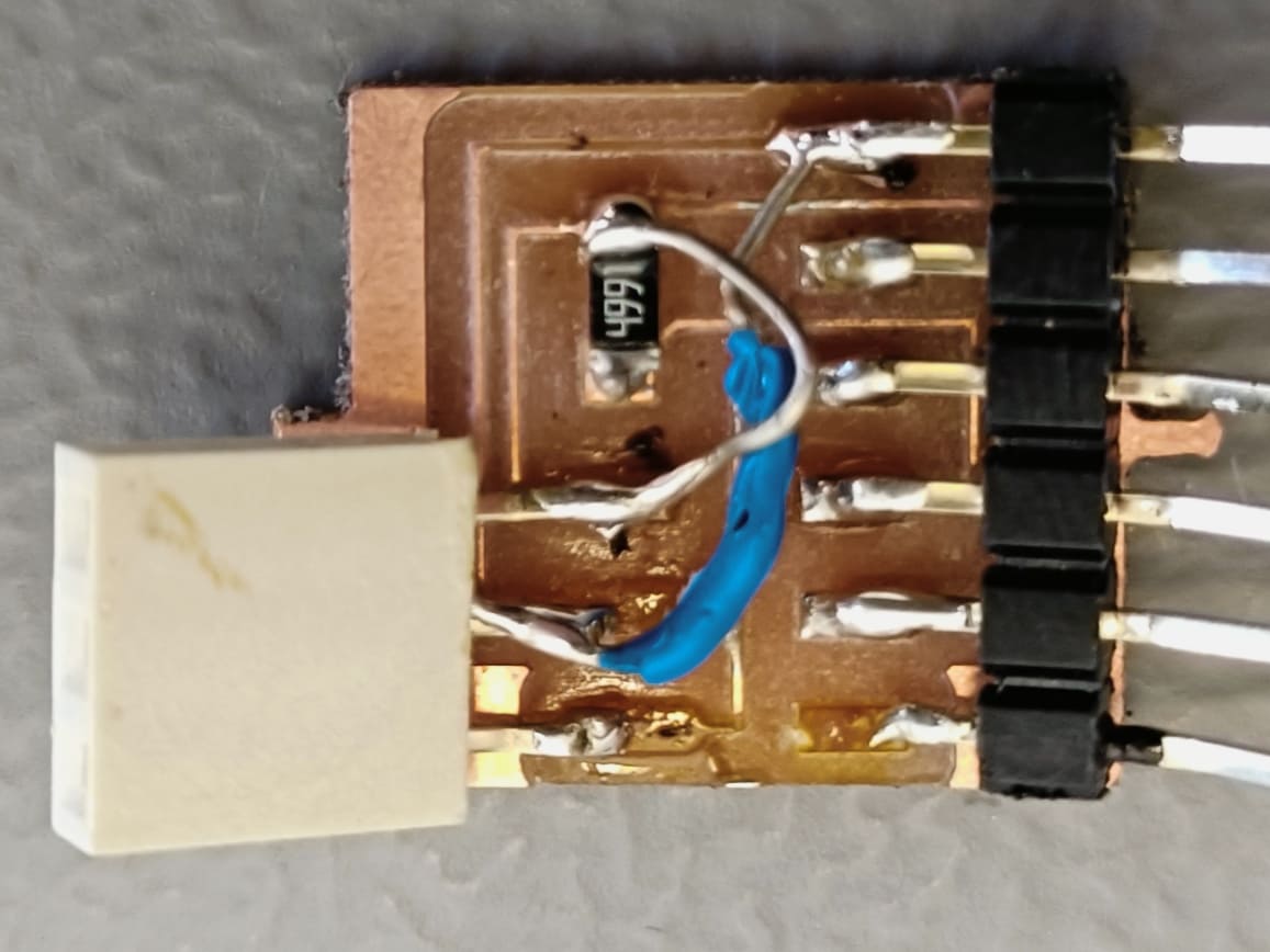
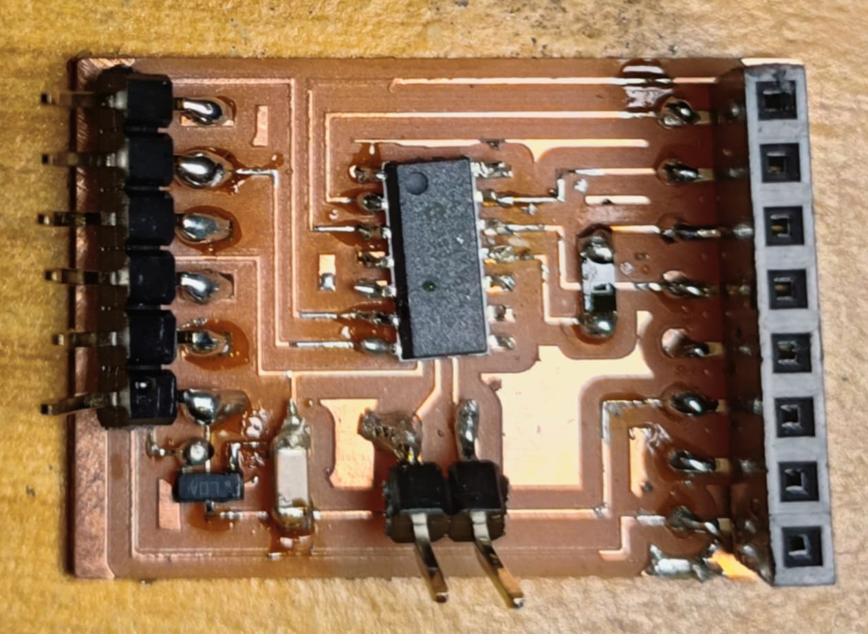
After soldering the components (yes, I kow y soldering could be better) I stacked them on top of each other. The serial to uart converter in particular I transported already connected to the premade RFID module. This resulted in some pins breaking. For 2 of them, the pads on the PCB itself came off.
Solution: Resolder the pins. Bridge the broken pads with wires. See picture below for more details.
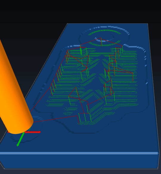
The edge cuts are shown above the traces after processing in Mods CE
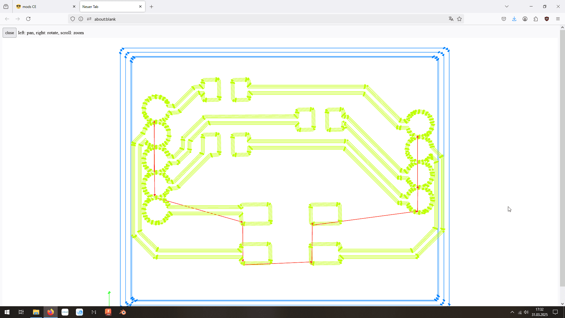
Solution: several people in the lab had the same problem. They milled their PCBs anyway and it works. This error seems to be based on the 3 dimensional graphic preview of Mods CE.
Variation: edgeCuts are not getting gcoded:
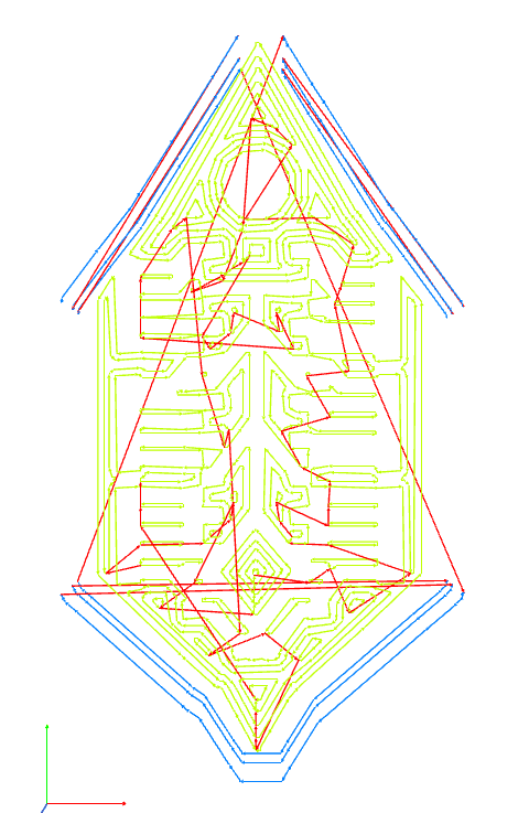
For some reason, there is a shadow on the edgeCut png.
Solution: none found yet.
The PCB is not straight
Solution: set the z-Axis 1mm lower
Using Carvera Desktop milling machine
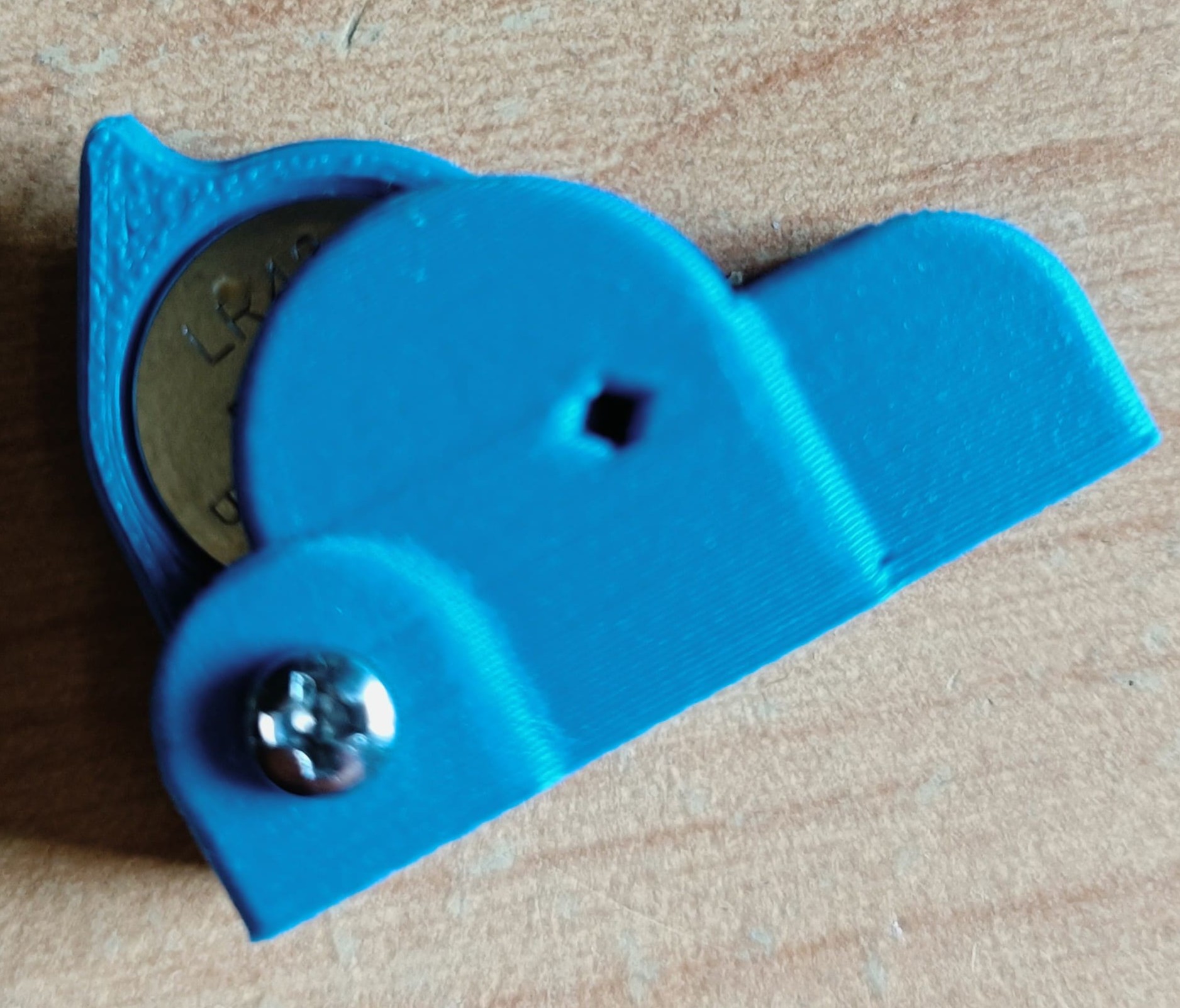
Remake and testing with the Wunderwuzzi Snail kit
While on a trip to Vienna, I discovered this robotic starter kit in a museum shop. I was instantly hooked because I had never seen a switch implemented that way.
Additionally, it uses a vibration motor to move forward just like in one of the most famous swarm robotics projects: The Kilobots. They are known for being able to achieve a lot of experiments in a variety of swarm robotic related research fields and for being super cheap. However, they are notoriously slow. This might be interesting for a future propagation type for the the puzzling robots, so I started testing with the little vibration motor.
Test results:
It moves way faster than the Kilobots (probably because of the amount of feet)! It also seems to move relatively straight (probably because of the way the feet are bent). It is a super cheap alternative to wheels. The movement directions can be guided by uneven surfaces. There are already prototypes of changing ground surfaces (example ArrayBot), so that is doable as well.
All in all, this system seems promising for the future. Here is a V2 I designed to counteract the weaknesses and stability issues of the one I bought:
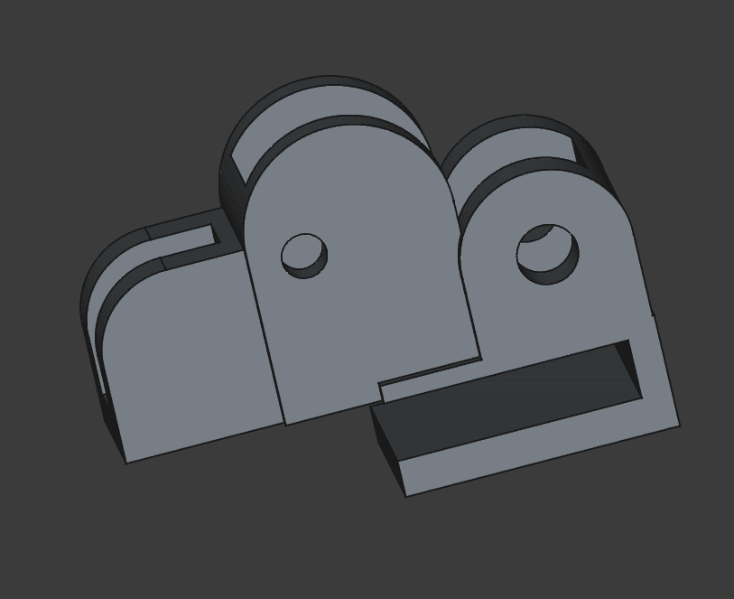
Download file:
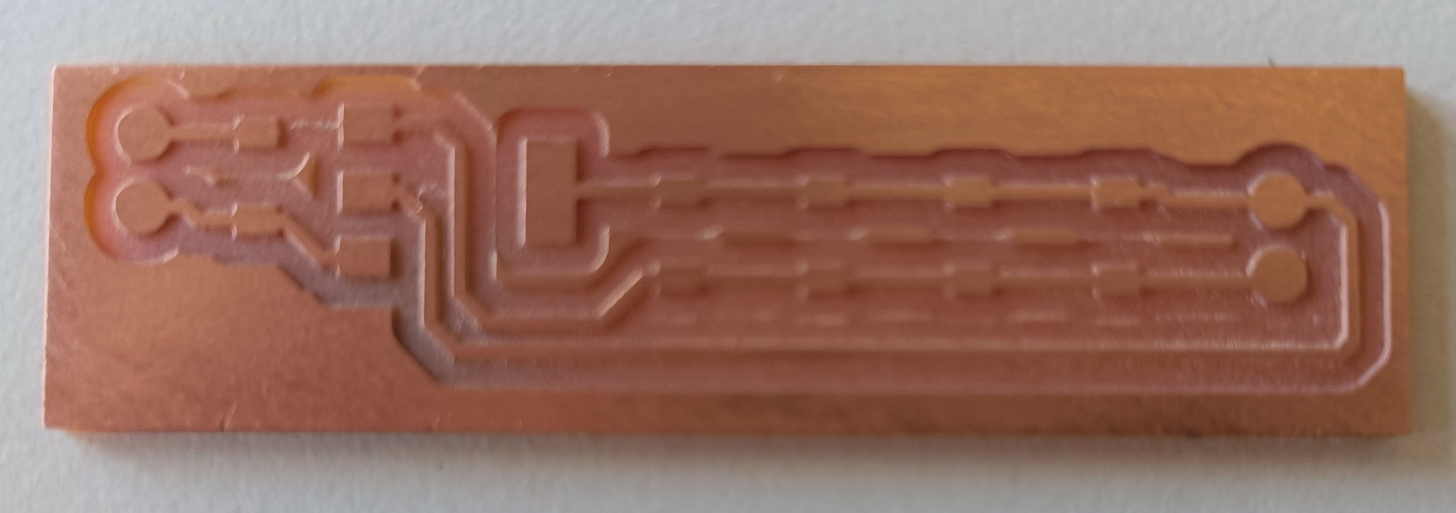
Linear Voltage Regulator
The RFID modules need a stable, low noise power supply of 3.3V. So, I designed one around a linear Voltage regulator IC in the lab.
Download files:
- you know the drill
Additionally I noticed that I can use the same PCB to amplify to 5V. The size and requirements of the ICs are the same. They only differ by the amount of output voltage.
Result:
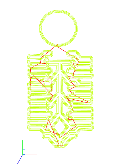
RFID module with AtTiny
Initially I used the breadboard to test the RFID modules. Then an alternative popped up in the lecture.
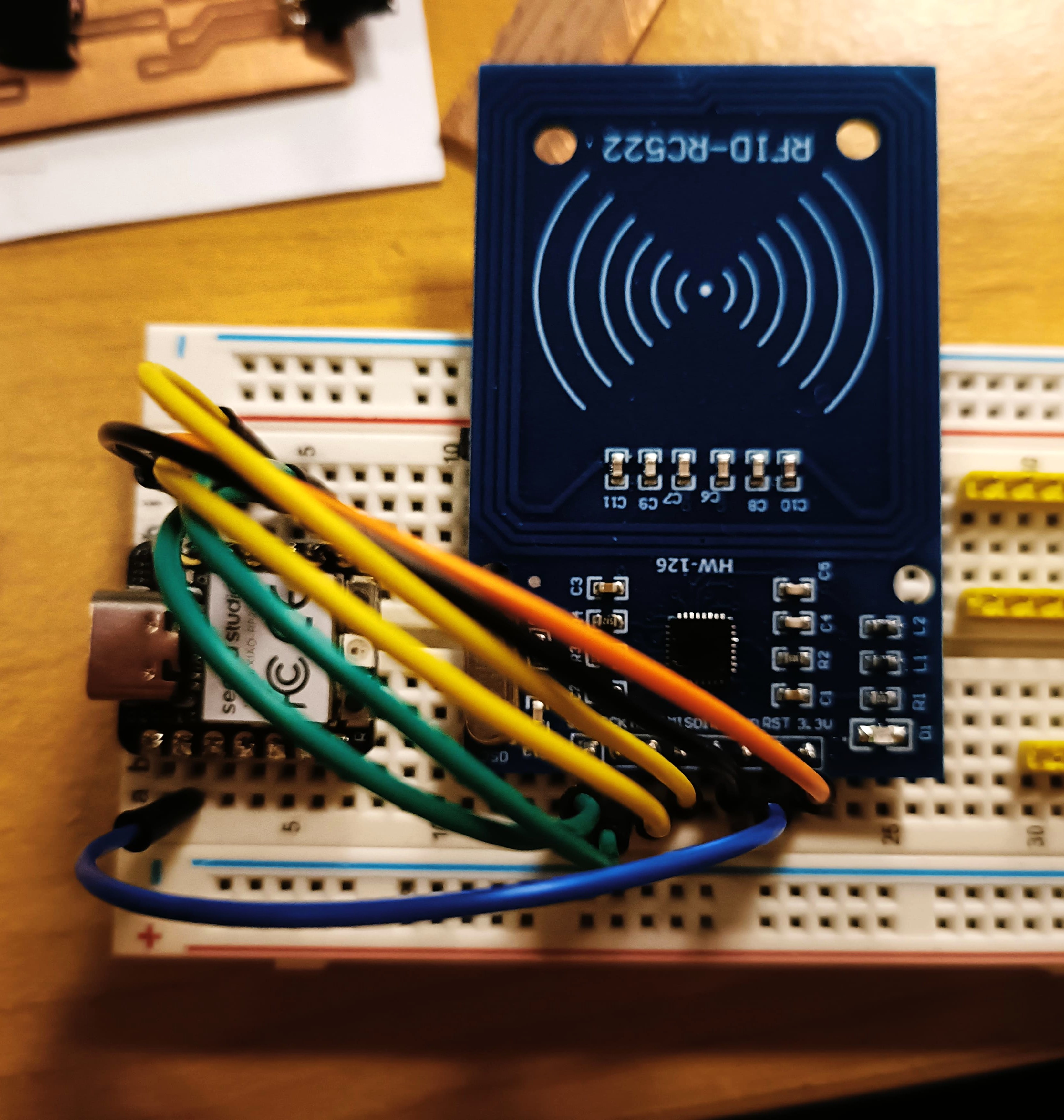
To program an AtTiny a UDPI programmer and a microcontroller board. There are a ton of programmers in the FAB cloud. I chose the Quentorres and the UDPI programmer by Adrian Torres.
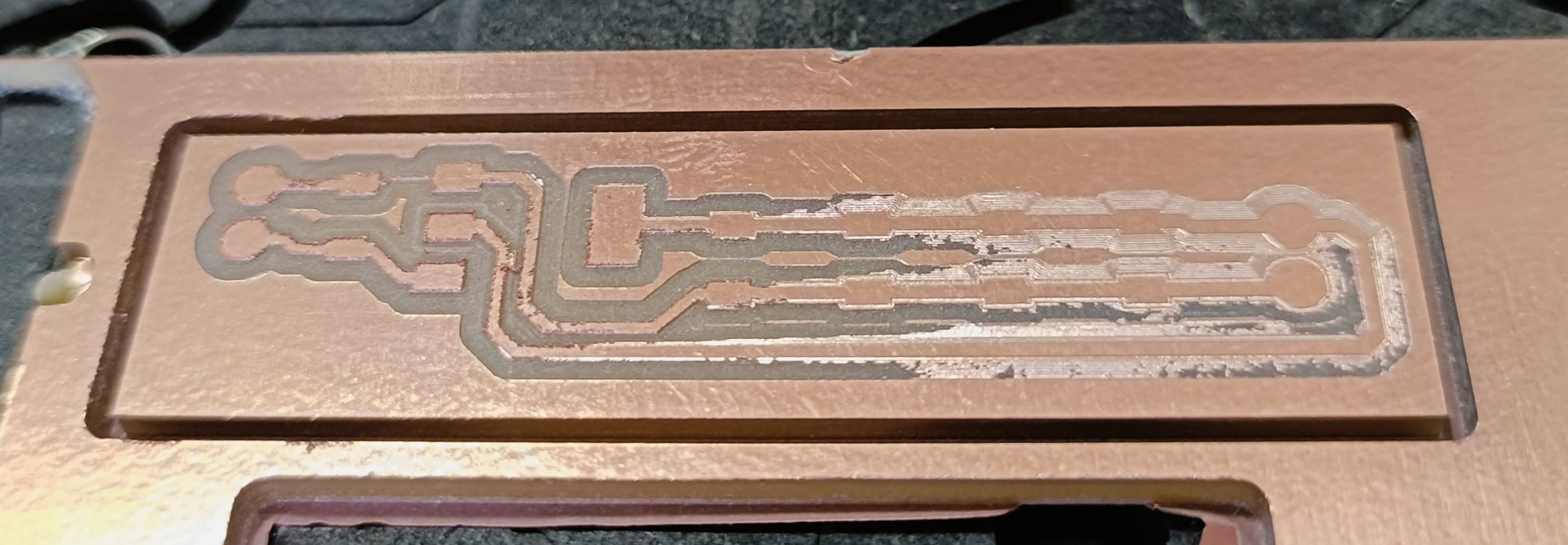
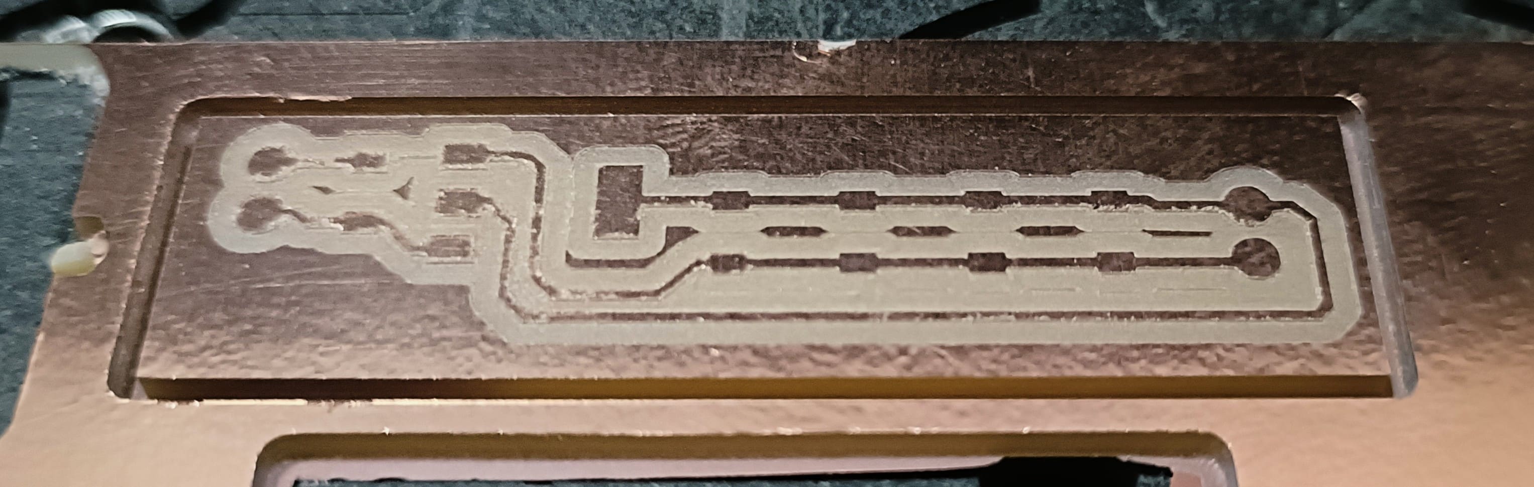
Download files RFID module: (credits to Neil)
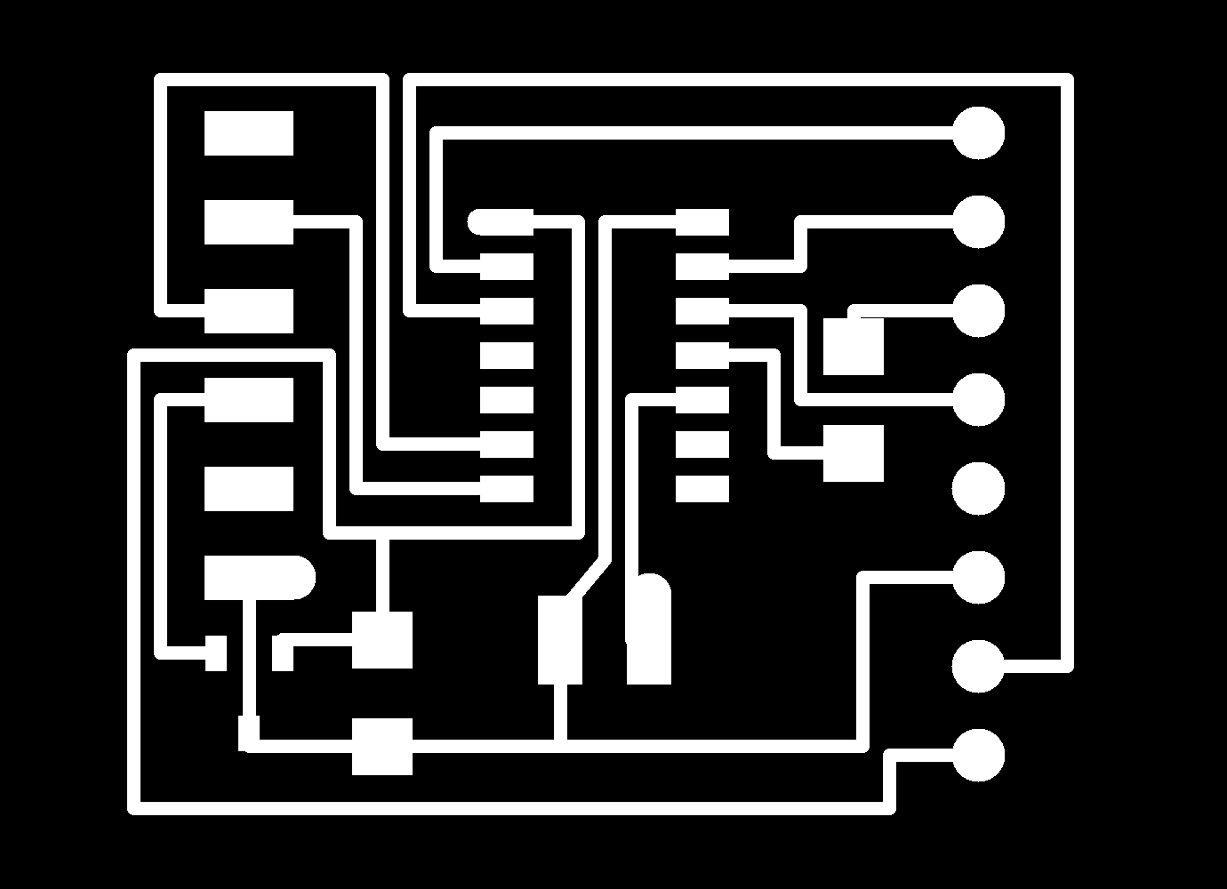
- Download: RFID AtTiny module traces PNG
- Download: RFID AtTiny module edgeCuts PNG
- Download: RFID AtTiny module NC
Download files UDPI programmer: (credits to Adrian)
Download files Quentorres: (credits to Quentin)
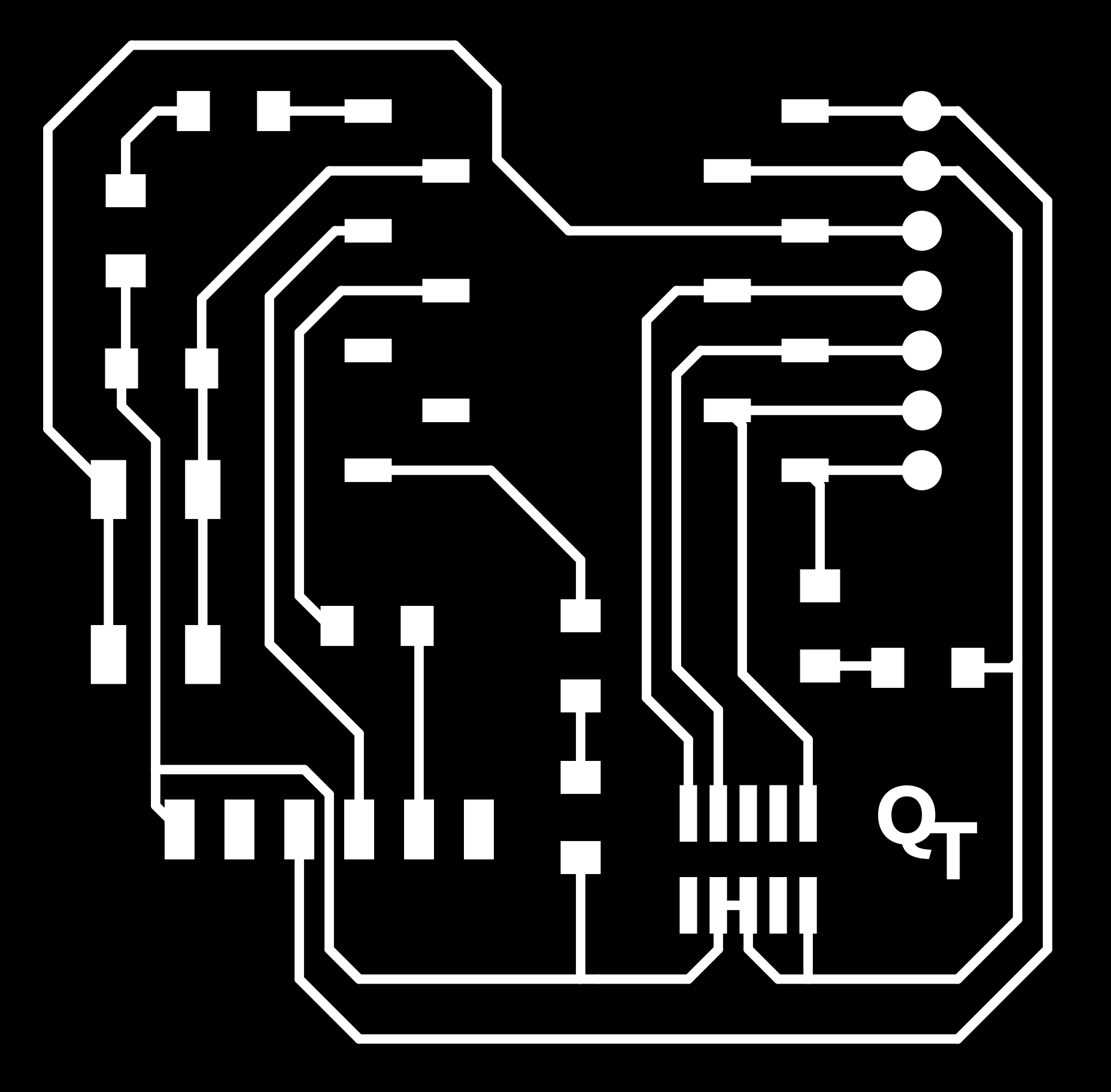
Work on puzzling Robots
Modules from this week: RFID modules and linear voltage regulator. The vibration motor is meant as a possible future propagation mechanism for the next version.
RGB button was already been covered in week 9. The linear voltage Regulator is the power supply for the RFID modules, which can also be directly connected to the microcontroller.
Only things missing is the charging system. The required modules are not available in the Fab Inventory. As such, I will probably buy one.