1. Electronics Manufacturing
This week, we will learn how to manufacture electronic circuit boards. In Week 6, we designed an electronic project, and this week, we will produce the circuit board. However, since the circuit board designed in Week 6 is relatively complex and not suitable for CNC cutting, I redesigned a simpler circuit board to verify the CNC cutting process and test its functionality.
1.1 Circuit Board Design
-
Copy and Simplify the Schematic Design
Fortunately, the XIAO ESP32S3 has excellent pin multiplexing capabilities, allowing us to select pins according to our needs and design a suitable circuit board.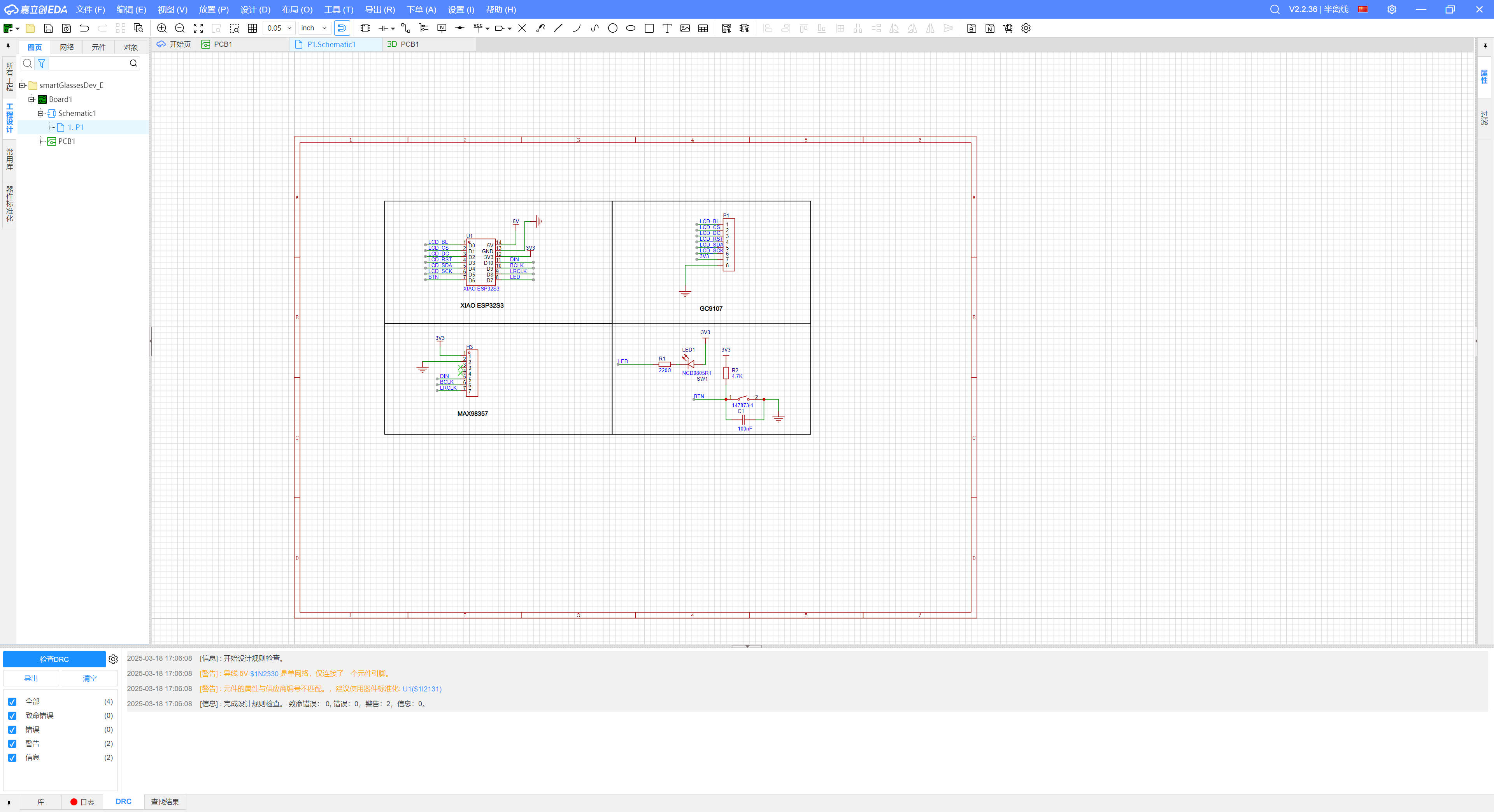
-
PCB Layout Design
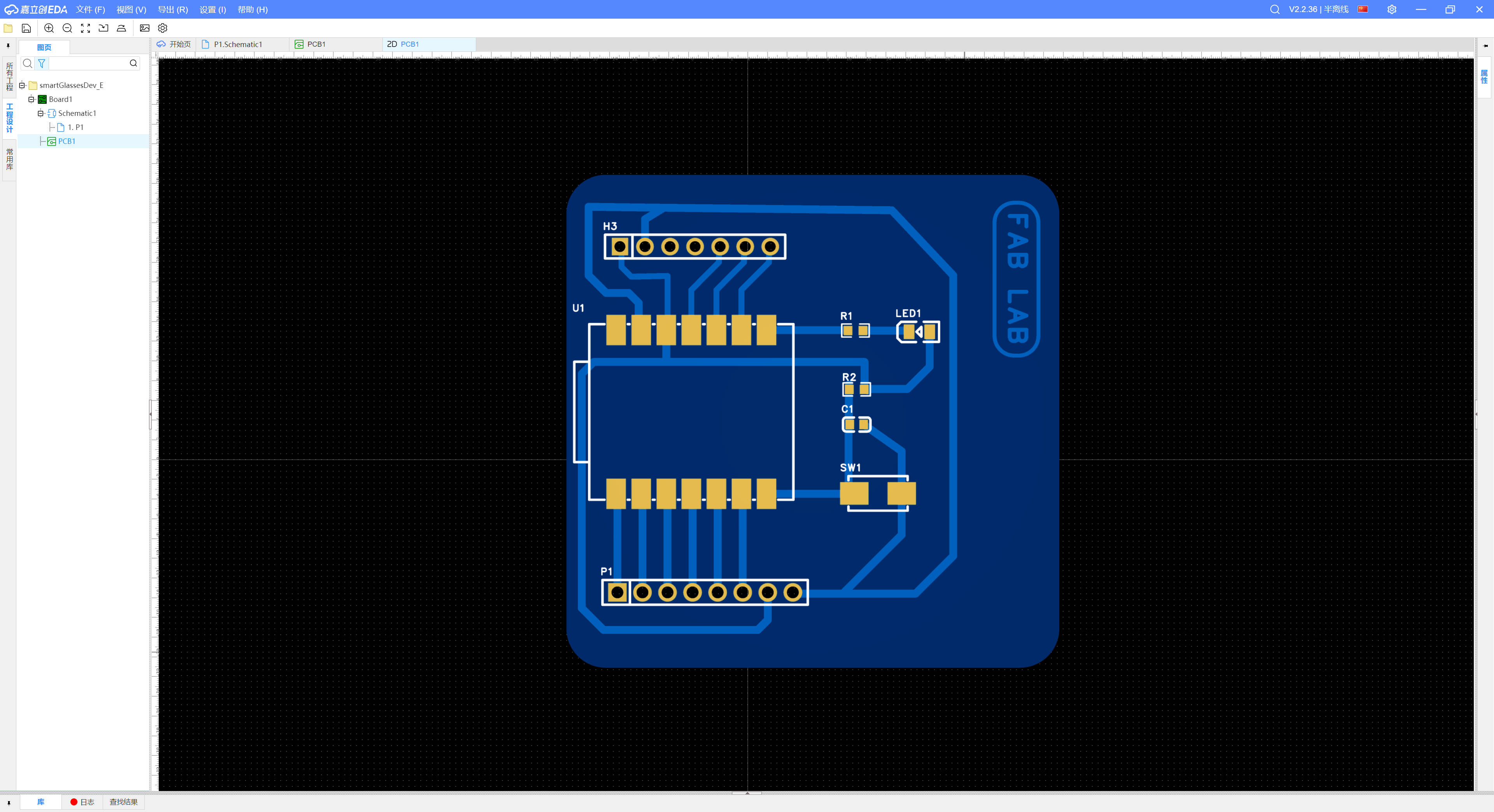
When designing the PCB layout, we maximize the spacing between components and wiring to facilitate CNC cutting. It is crucial to ensure the traces are thick enough for proper conductivity and that there is adequate spacing between different circuit paths to prevent short circuits. The placement of components should also be optimized to minimize the complexity of wiring and improve stability.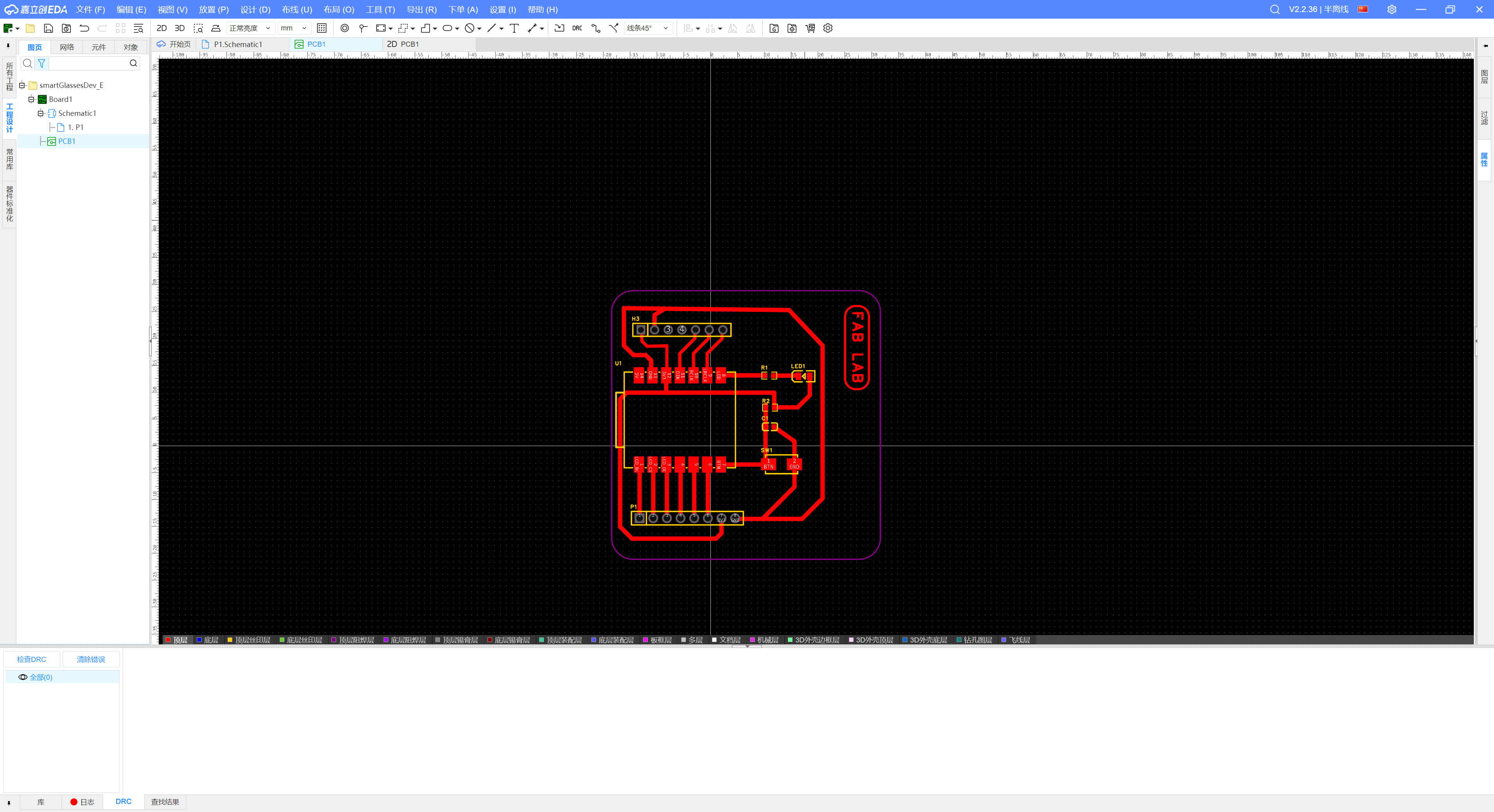
1.2 Exporting Gerber Files
After completing the PCB design, we export the Gerber files, which contain the necessary manufacturing data for producing the circuit board. These files include layers for copper traces, drilling, silkscreen, and outlines, ensuring that the CNC machine has all the necessary information for accurate production.
1.3 Generating PNG Files
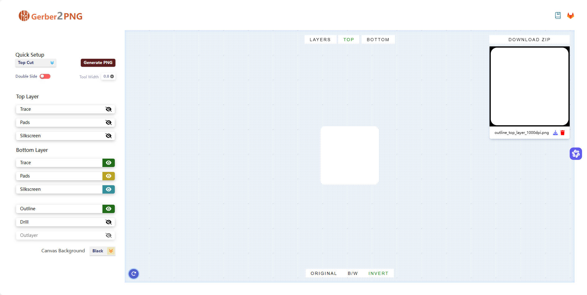
We use Gerber2PNG to convert Gerber files into PNG format for CNC cutting. This process involves generating high-resolution images of the circuit traces and the board outline.
- Upload Gerber Files
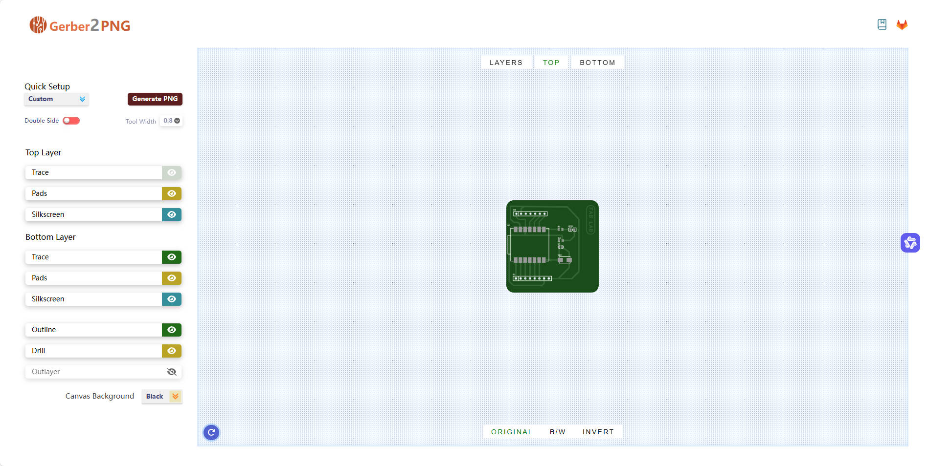
- Select the Layers to Generate
Choosing the correct layers ensures that we get a clear representation of the circuit paths and the board shape.
- Generate PNG Files
The generated PNG files provide a visual reference of the circuit board layout before proceeding with CNC cutting.
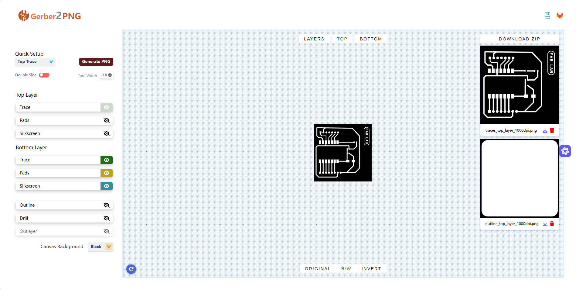
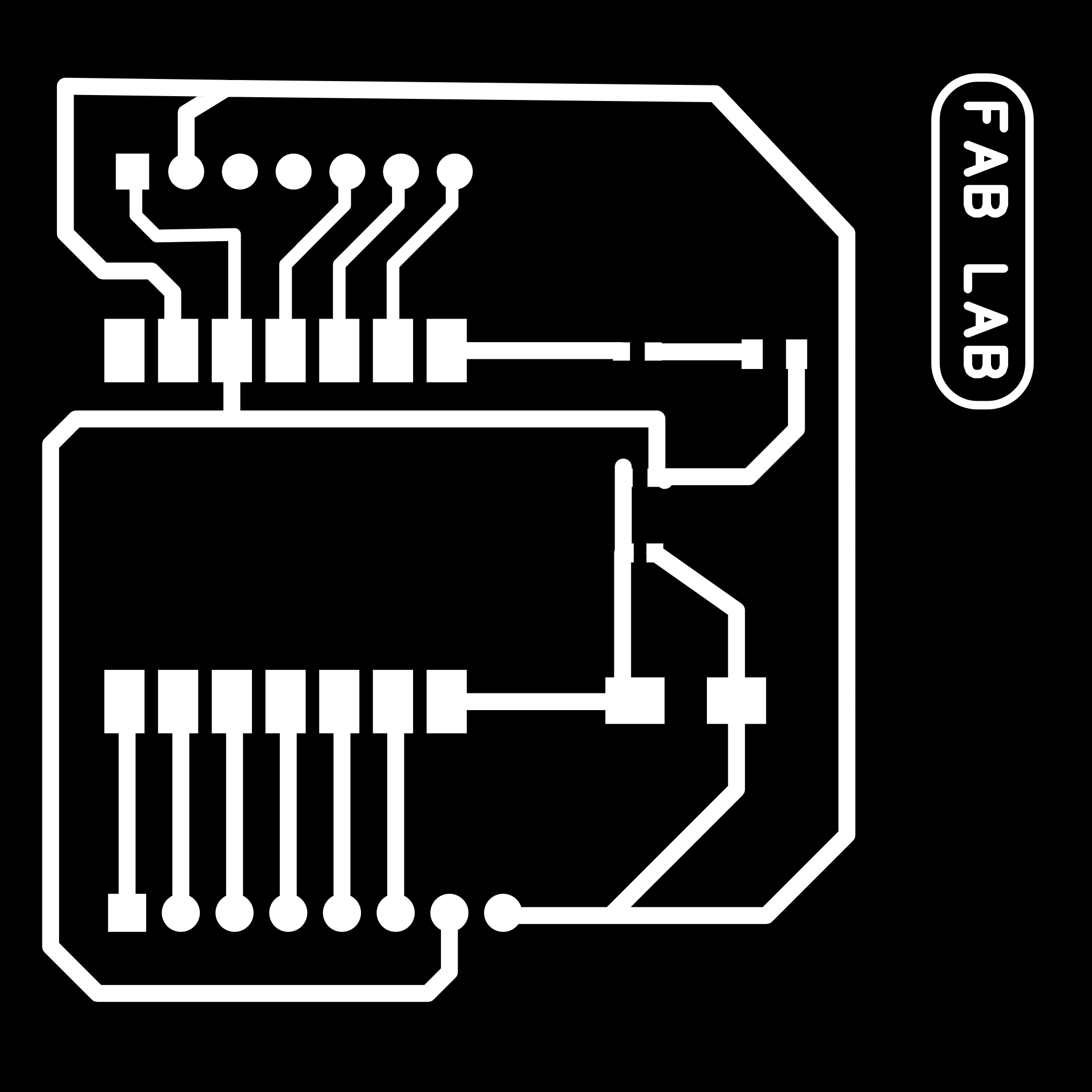
Finally, we generate two PNG files:
- One for the circuit traces
- One for the board outline

1.4 Generating Gcode Files
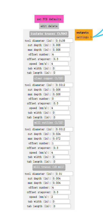
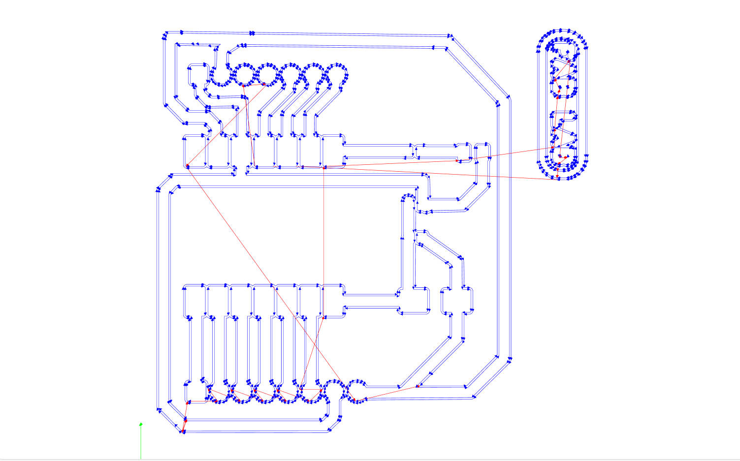
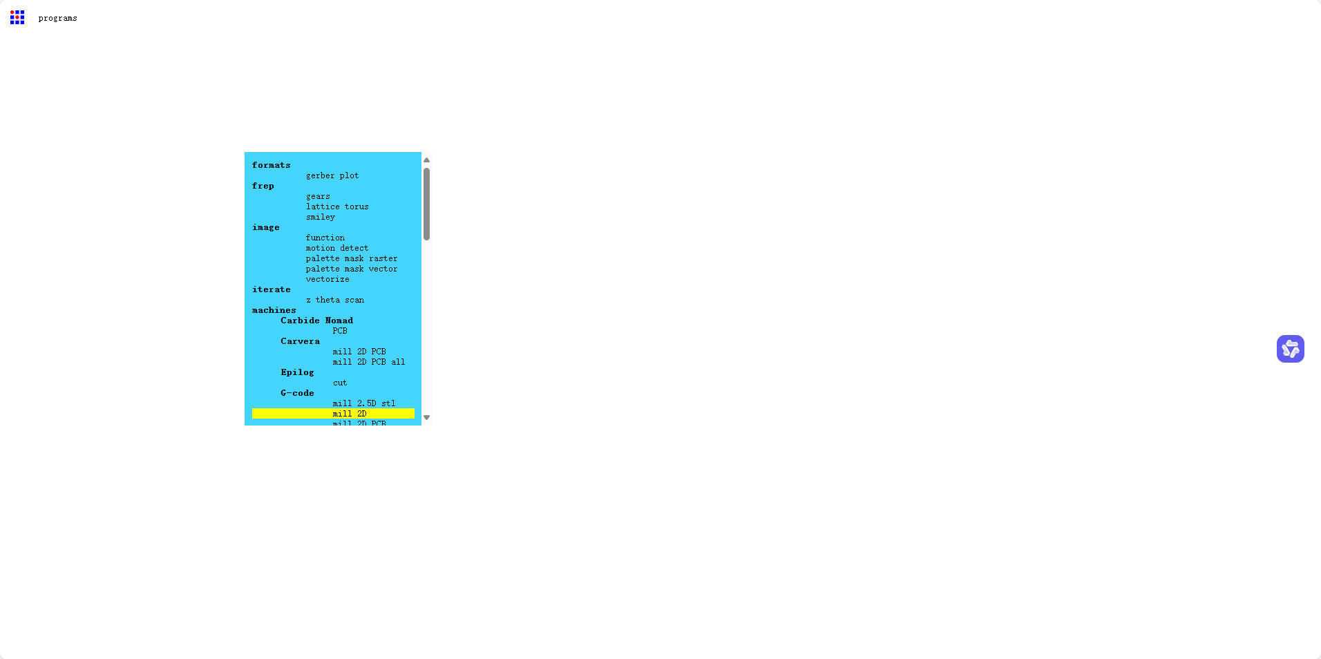
We use Mods CE to convert PNG files into Gcode files for CNC cutting. Gcode is a set of machine instructions that control the CNC milling process.
- Upload PNG Files
- Select Cutting Parameters
Setting the correct parameters, such as cutting depth, tool diameter, and feed rate, is crucial to ensure precise milling without damaging the board.
- Generate Gcode Files
Once the parameters are set, we generate the Gcode files, which will guide the CNC machine in cutting the circuit board accurately.
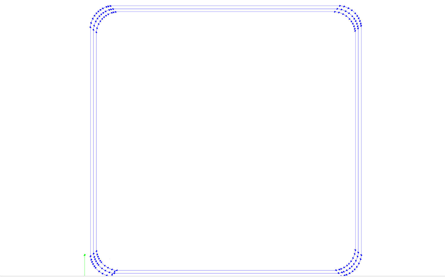
Finally, we generate two Gcode files:
- One for the circuit traces
- One for the board outline
1.5 Manufacturing the Circuit Board
Understanding CNC Machine Operation
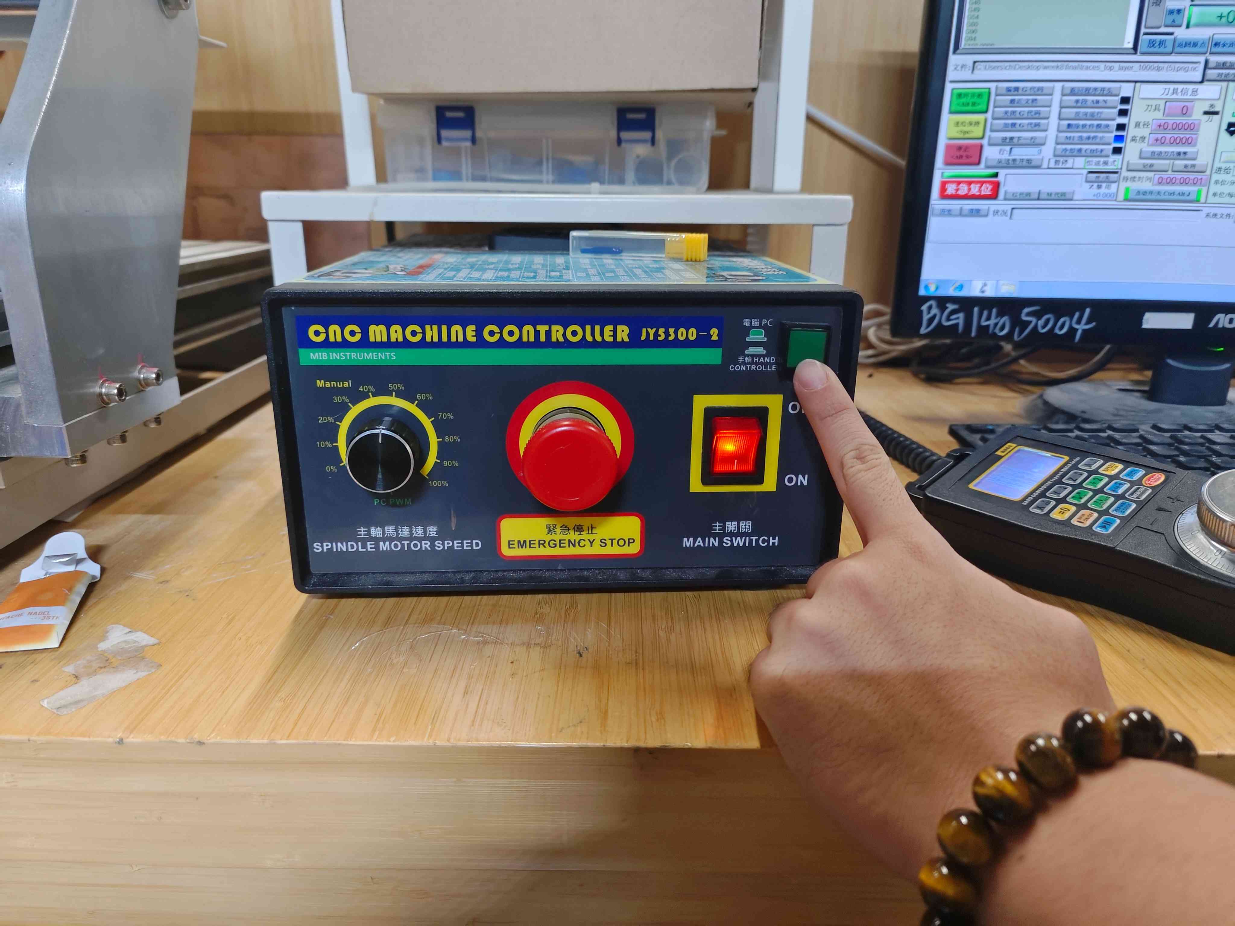
Before starting the cutting process, it is essential to understand the basic operation of the CNC machine.
- Emergency Stop
Familiarizing yourself with the emergency stop button is critical for safety in case of machine malfunction.
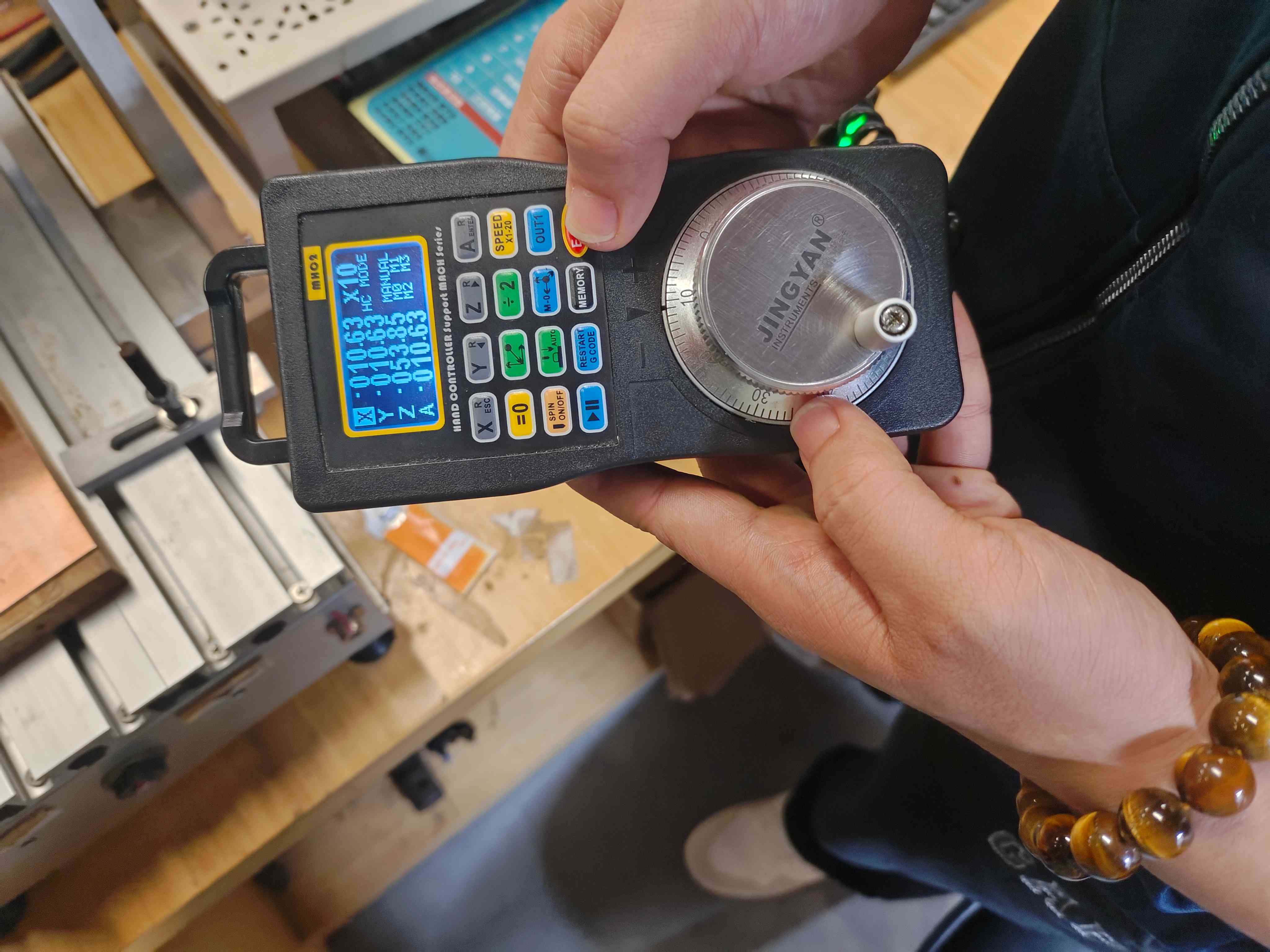
- Handwheel Operation
The handwheel is used for manual control of the machine's movement and positioning.
Installing Materials and Tools
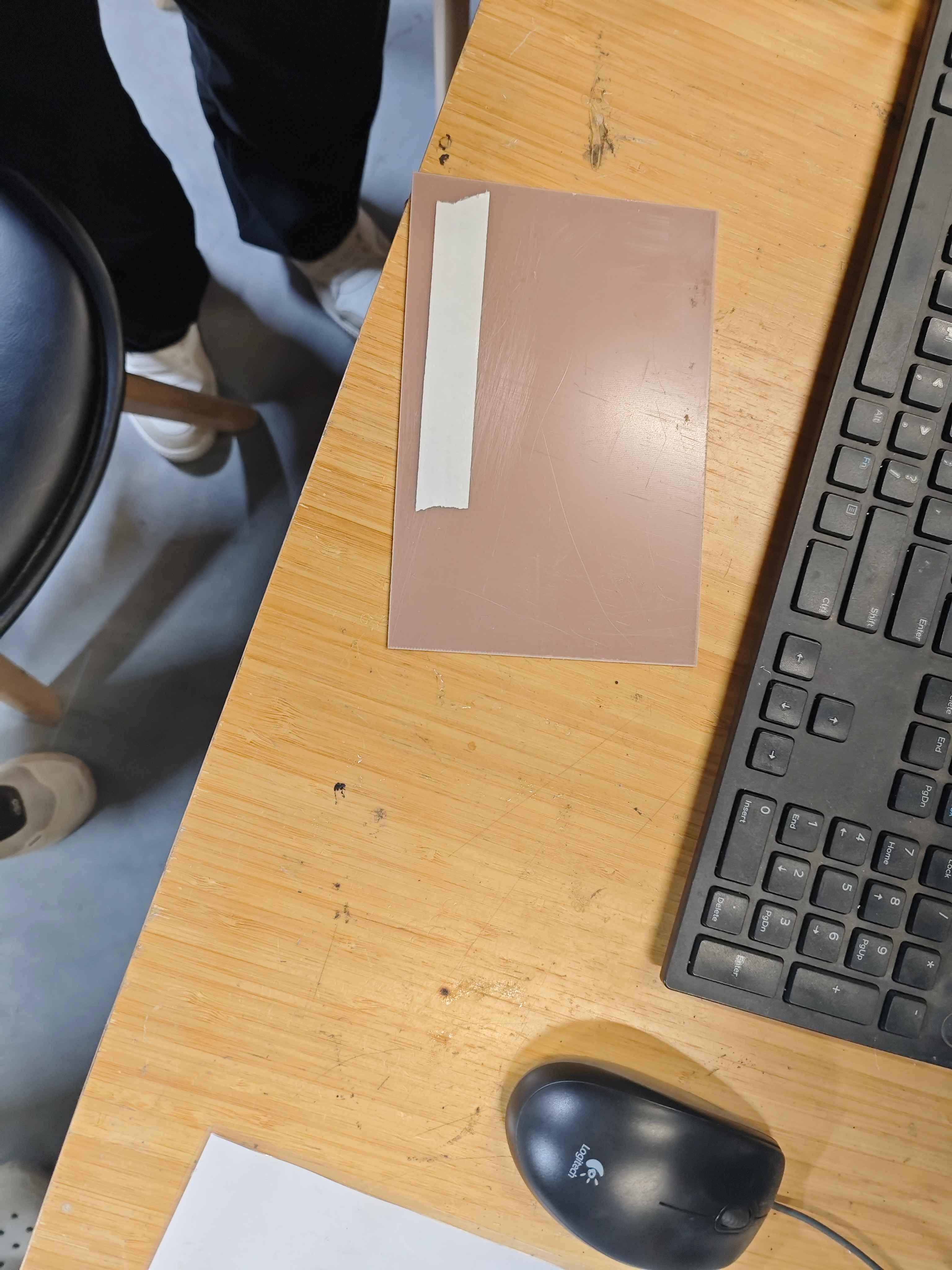
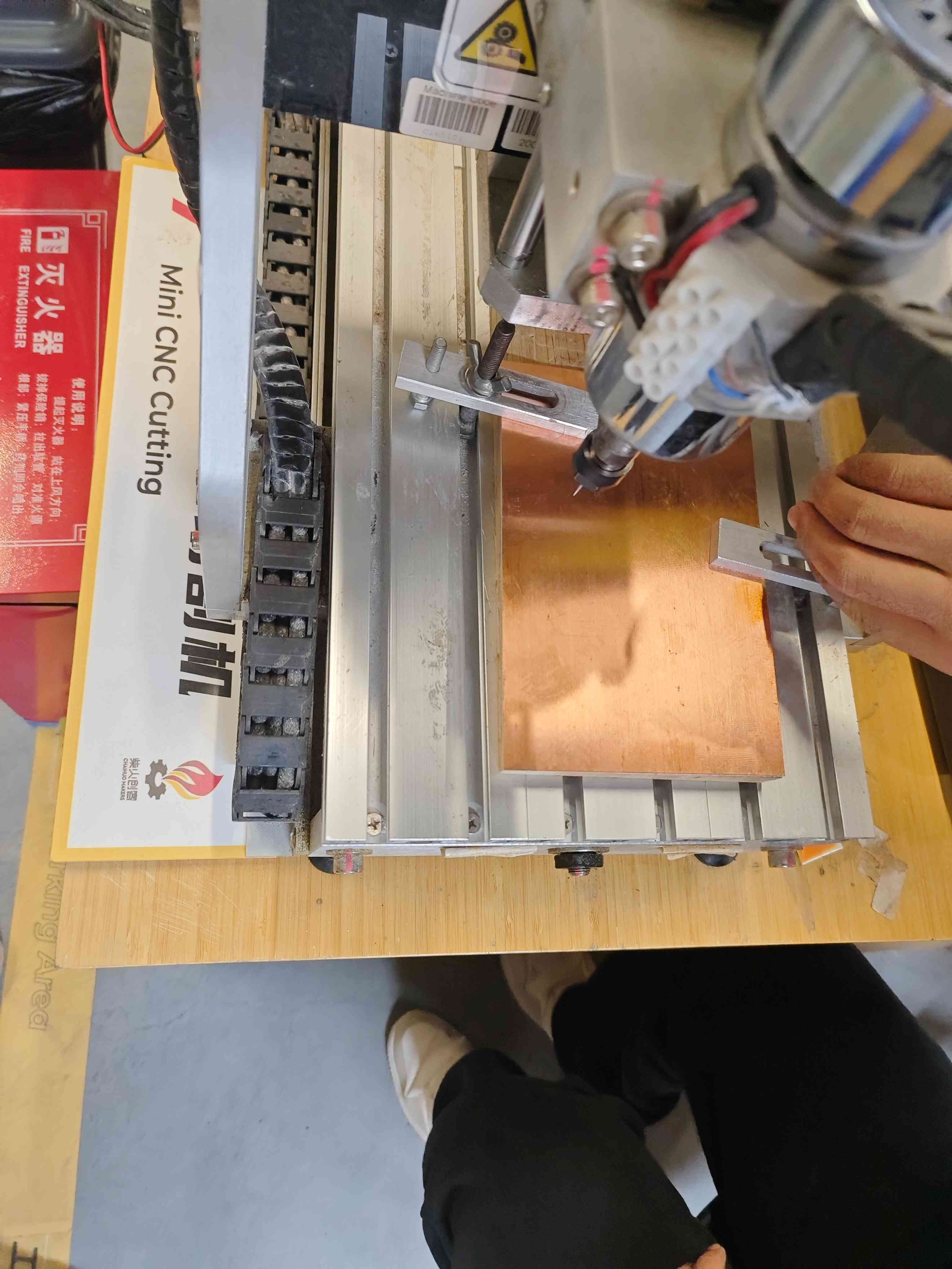
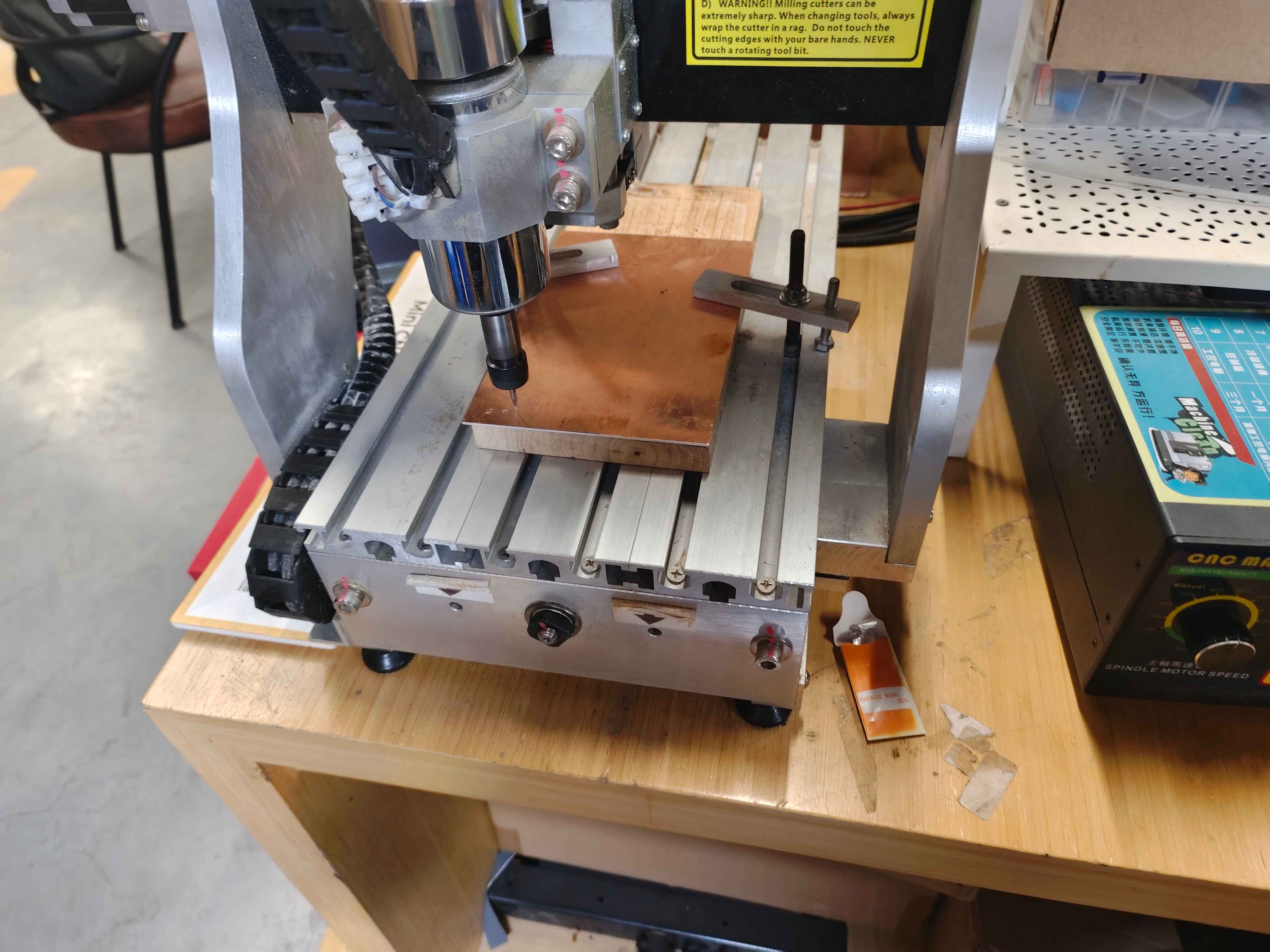
- Installing Copper Board
Securely mounting the copper board on the CNC machine is essential to prevent shifting during cutting. Double-sided tape or clamps can be used for this purpose.
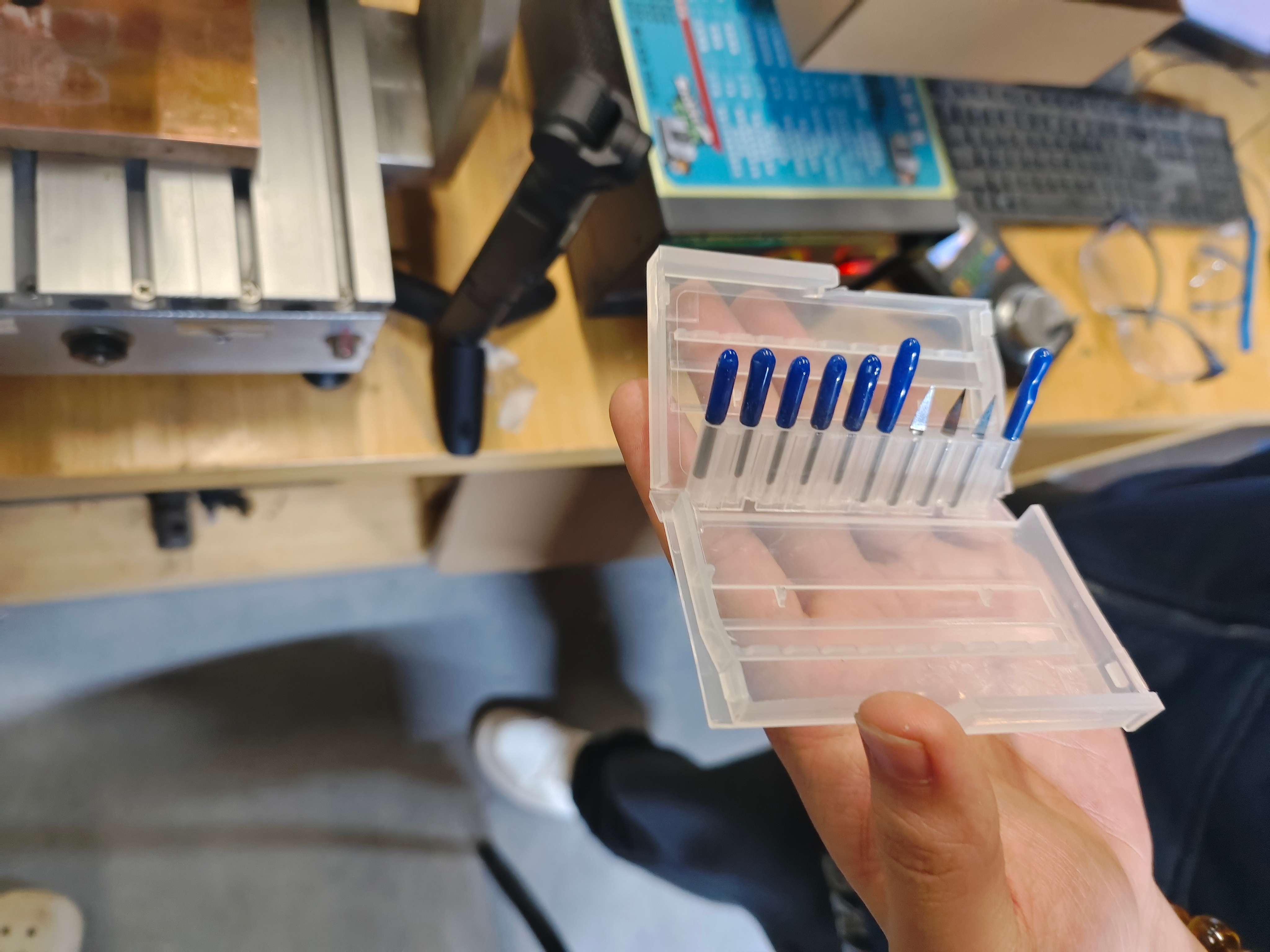
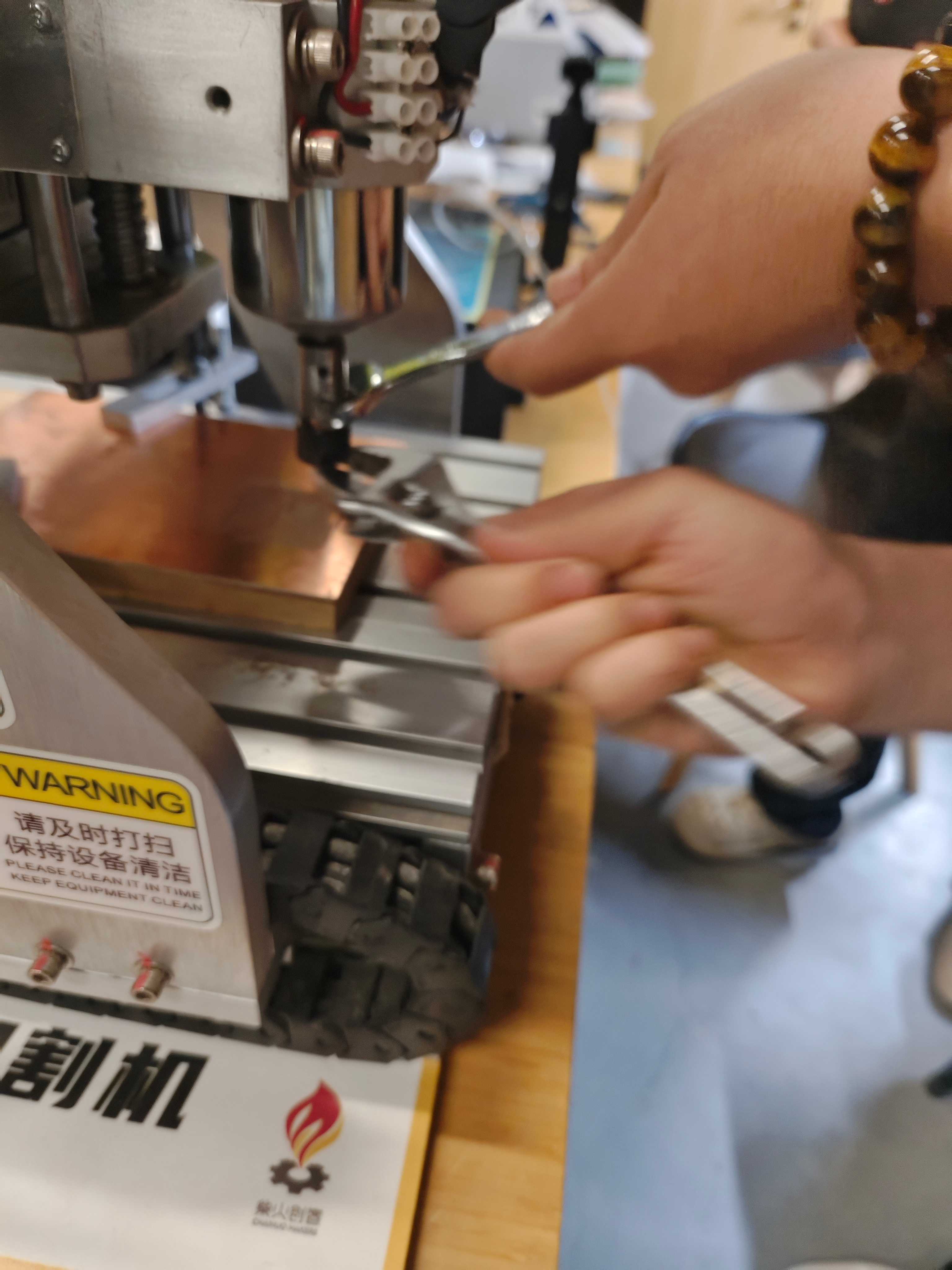
- Installing the Cutting Tool
The appropriate milling bit must be installed for cutting traces and outlines. Properly tightening the tool ensures precision and prevents tool slippage.
Setting Up the CNC Machine
- Zero Point Calibration
Before cutting, calibrating the machine to the correct zero point ensures that the cutting starts at the precise location. This step involves adjusting the X, Y, and Z axes.
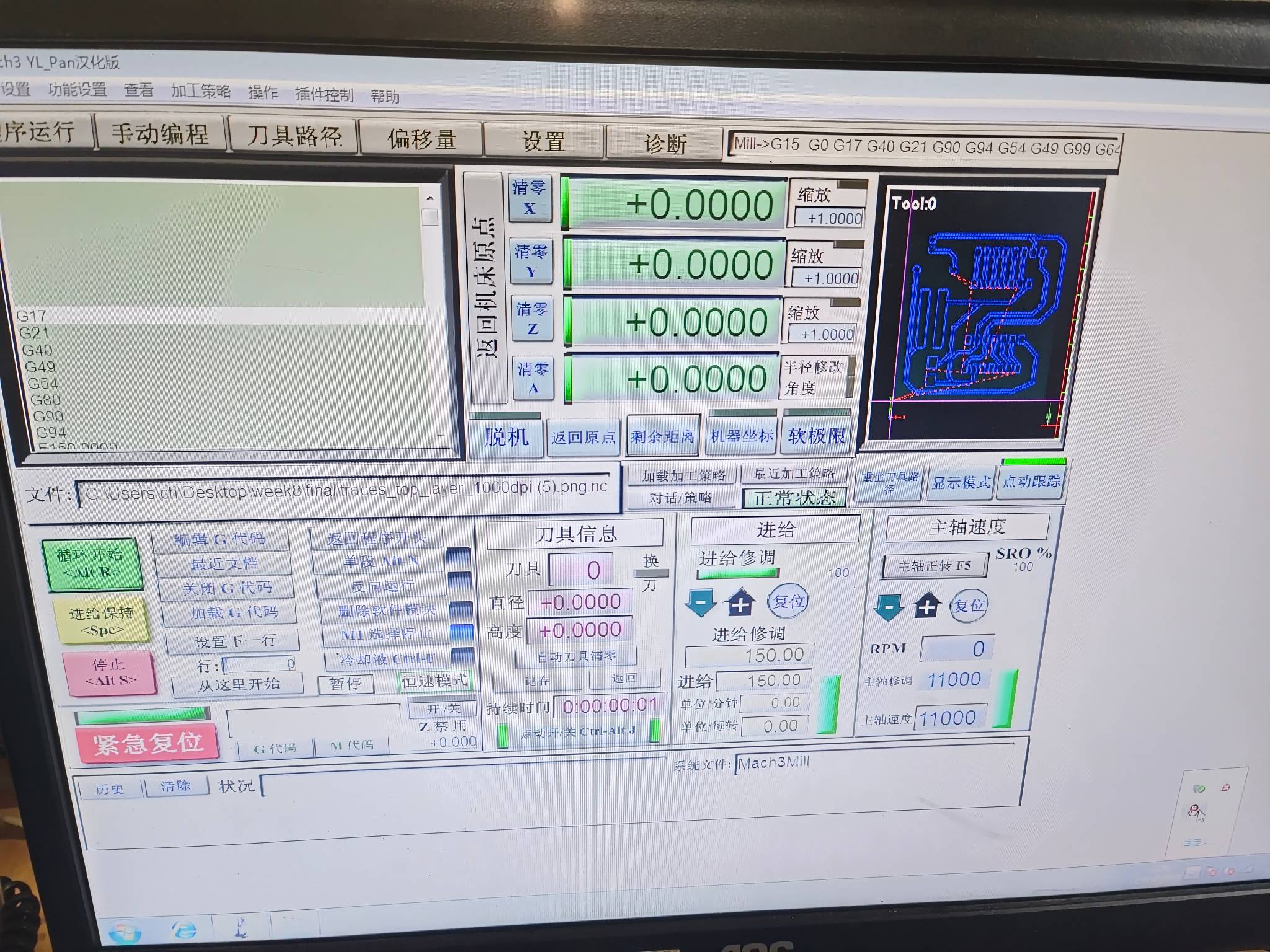
- Importing Gcode Files
The Gcode files generated earlier are now loaded into the CNC software for execution.
Performing CNC Cutting
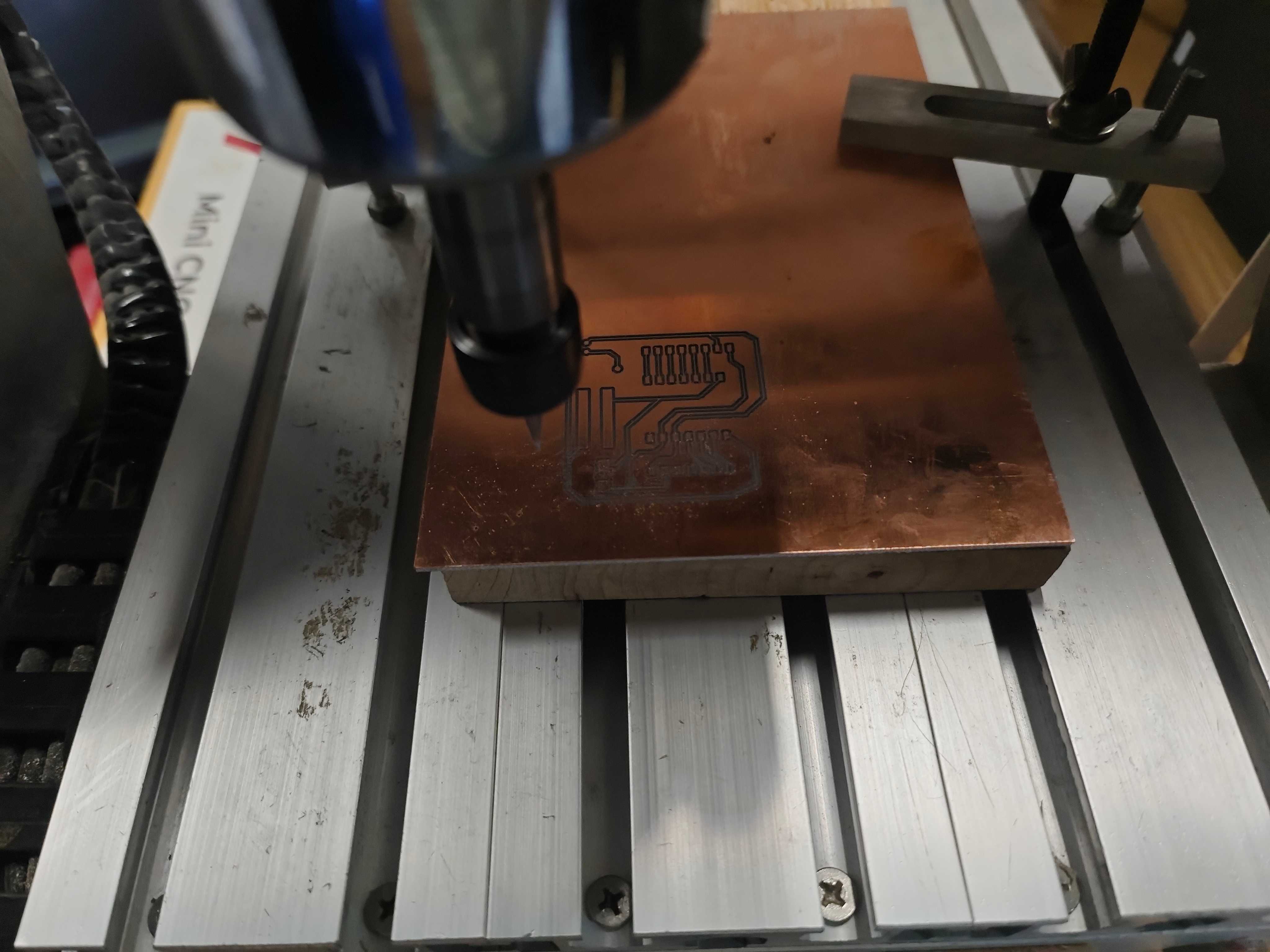
- Executing the Cutting Process
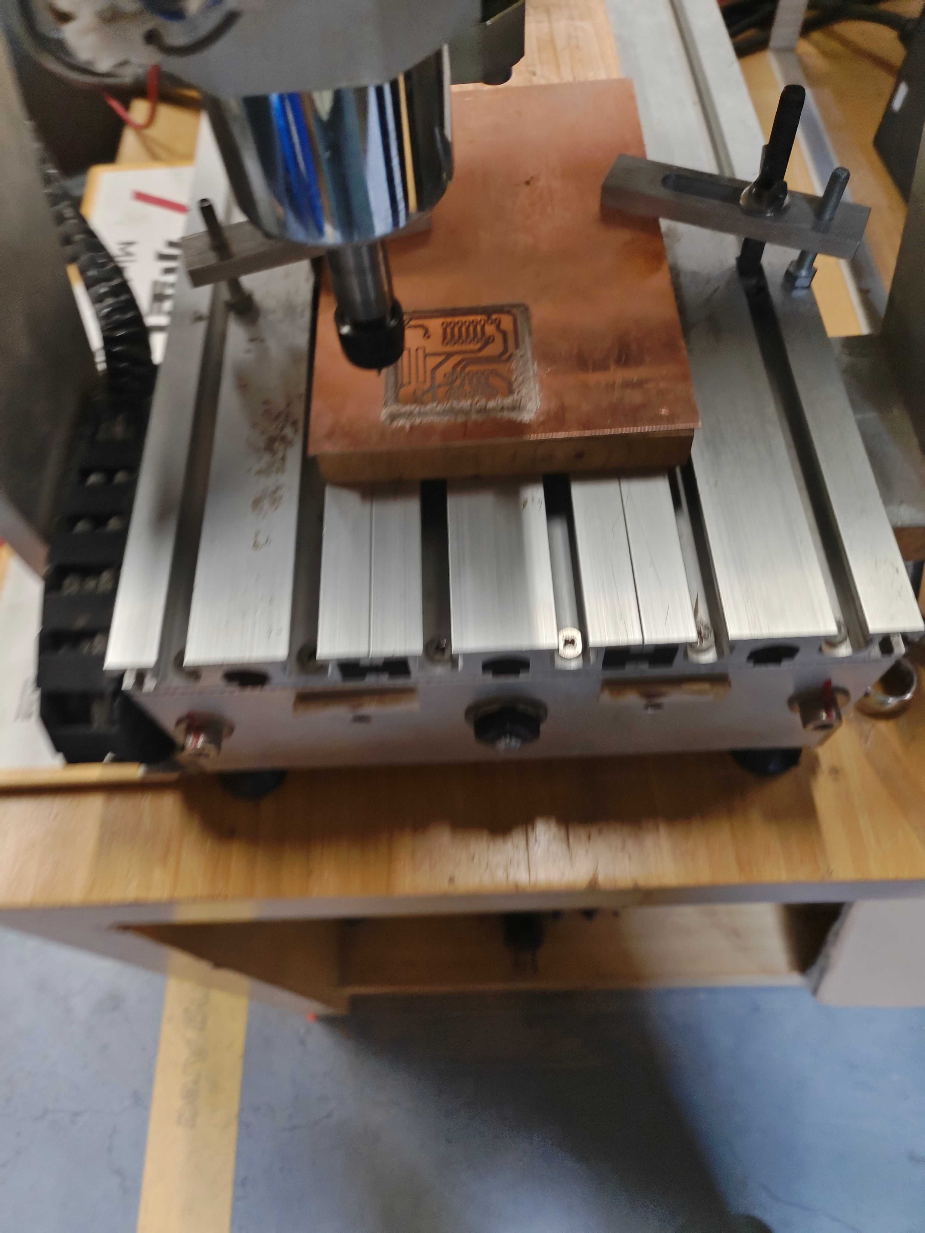
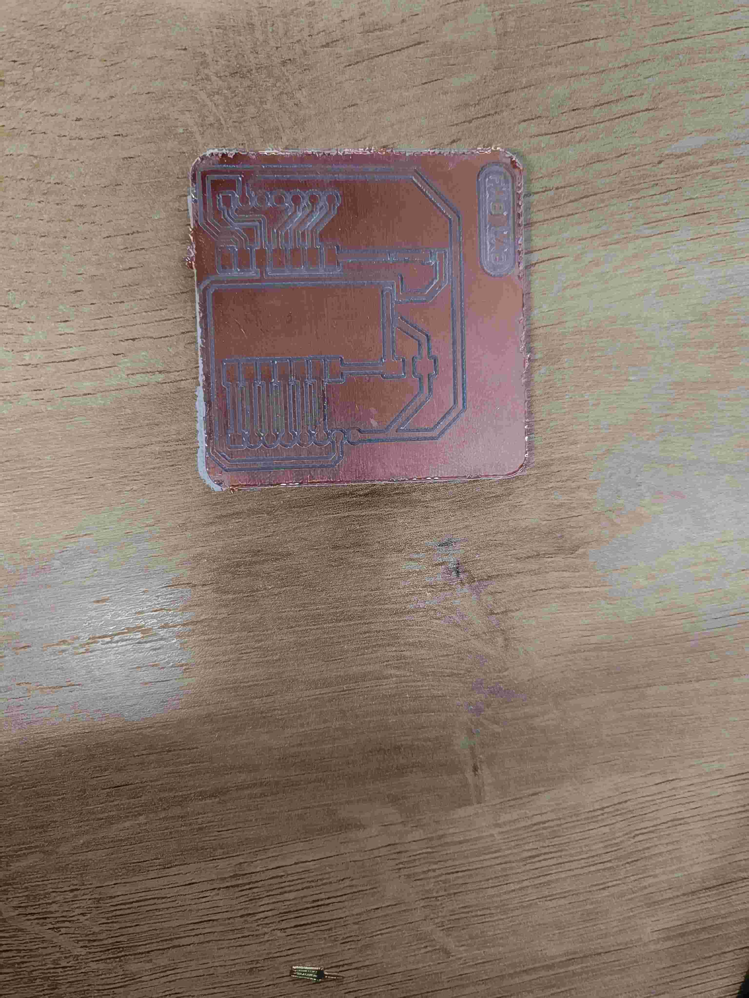
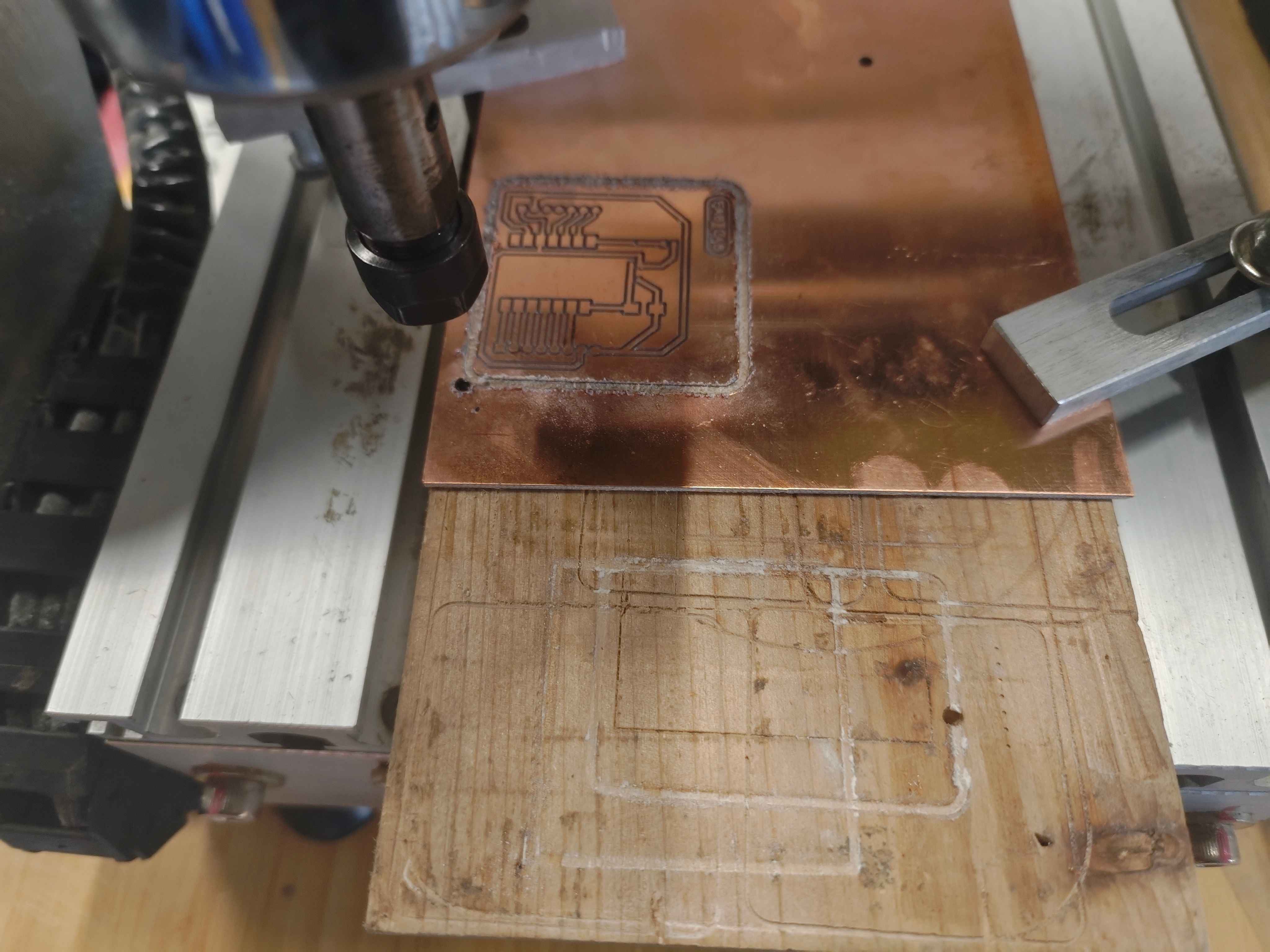
Once the setup is complete, we start the cutting process. The CNC machine follows the Gcode instructions to carve out the traces and cut the board outline. Regular monitoring is necessary to ensure proper cutting and prevent material damage.
Testing the Circuit Board
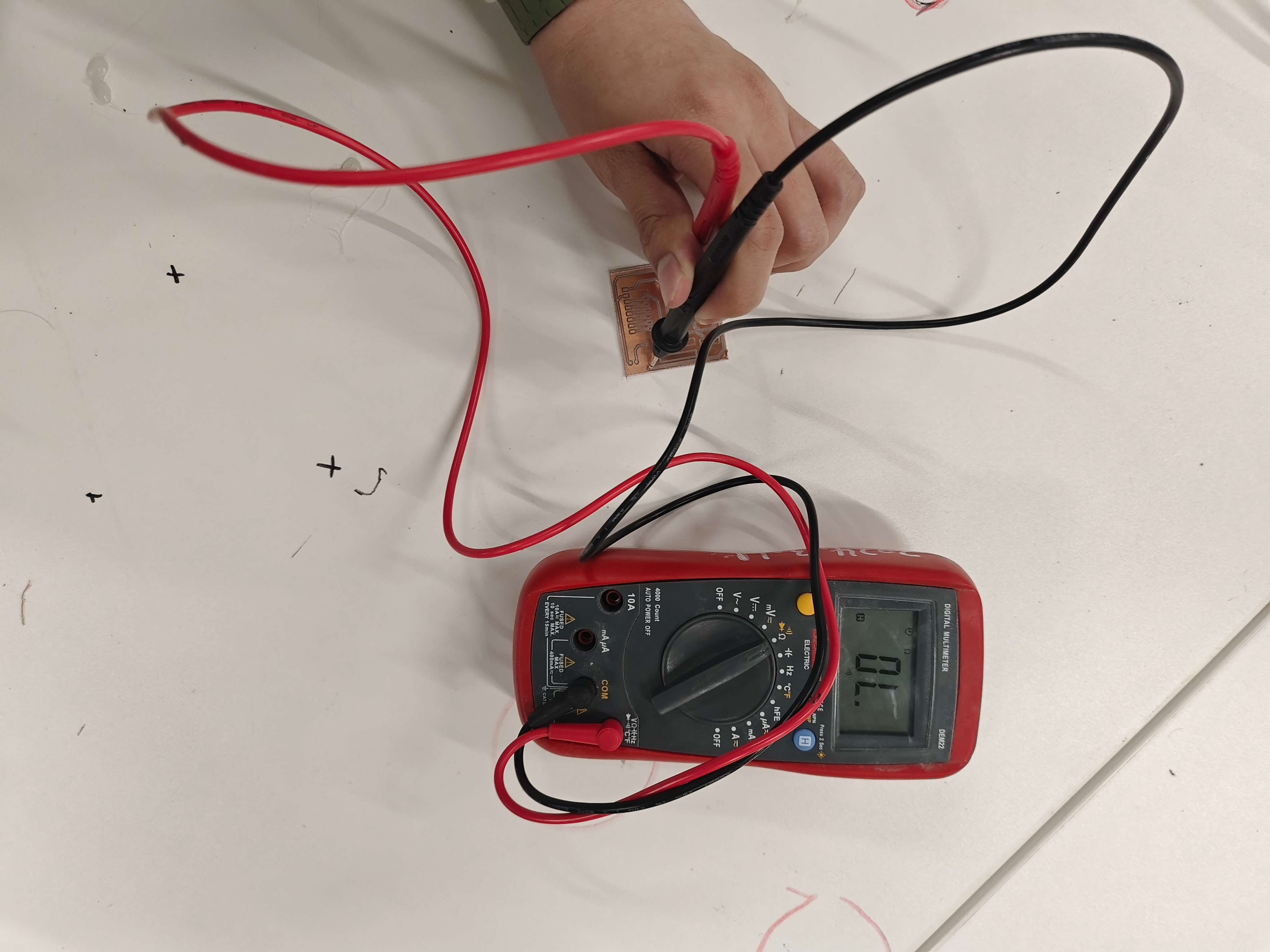
After the cutting process, the board needs to be tested for continuity and shorts using a multimeter. This step ensures that the circuit paths are correctly formed and that there are no unintended connections.
1.6 Soldering Components
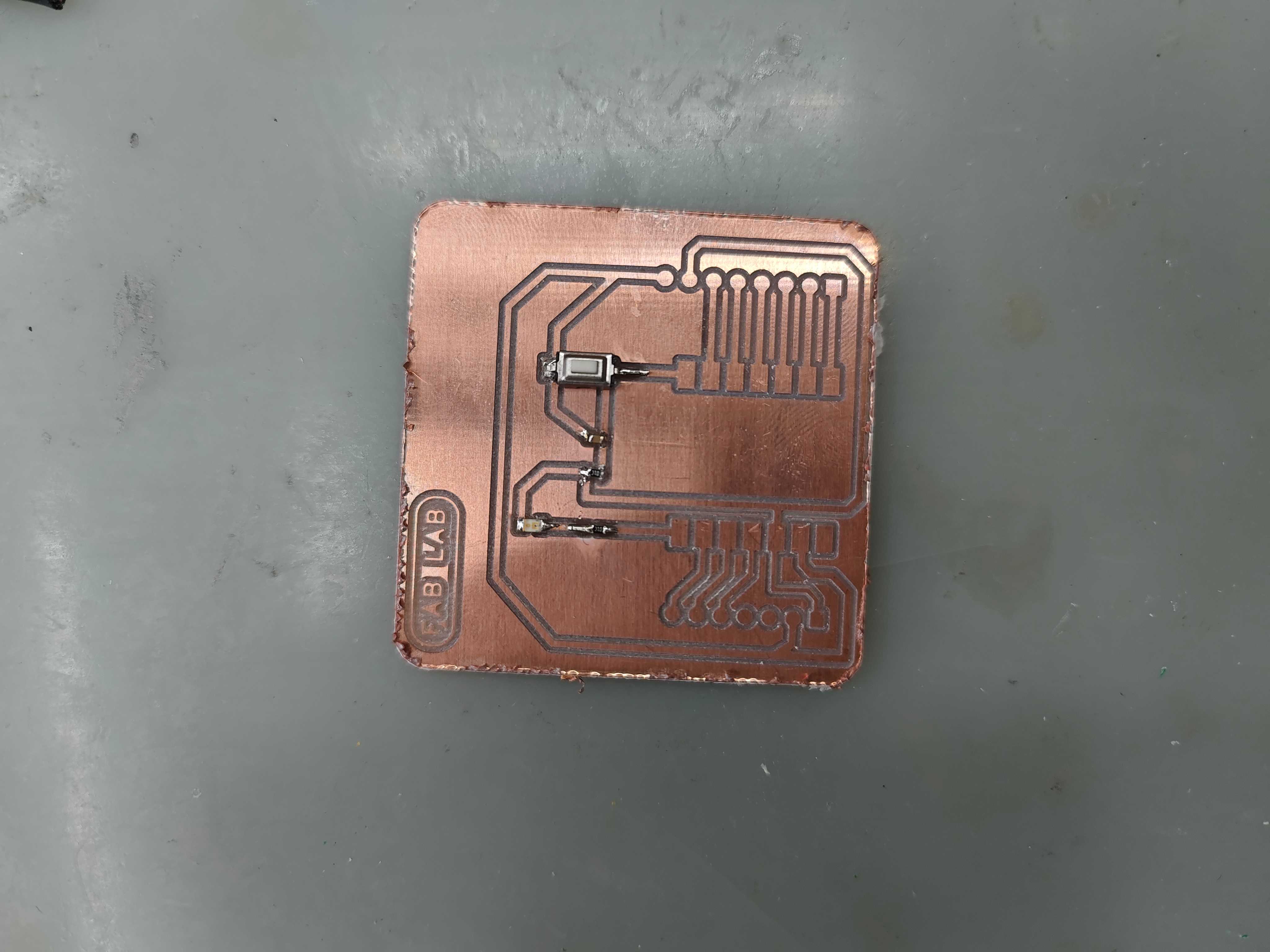
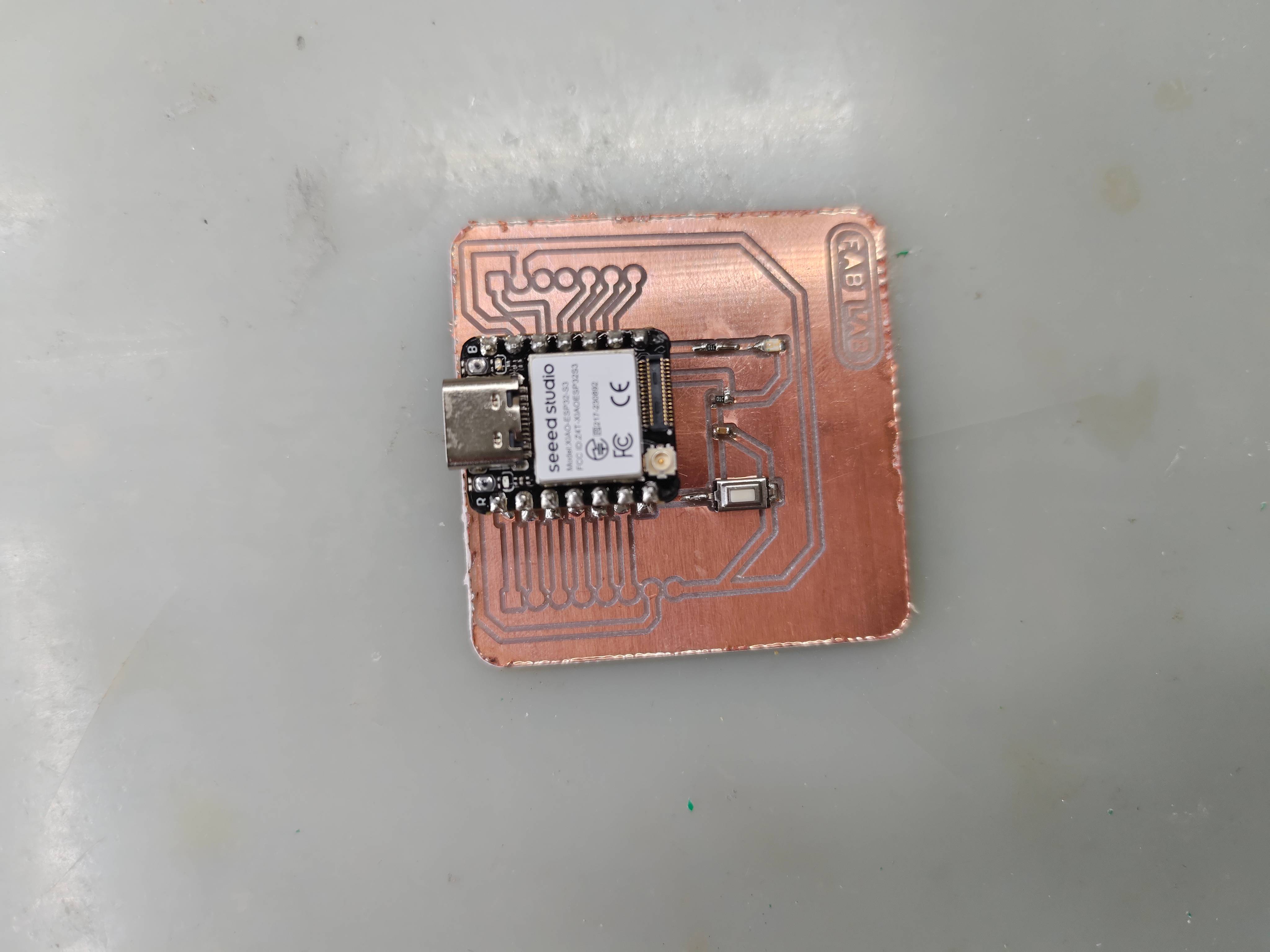
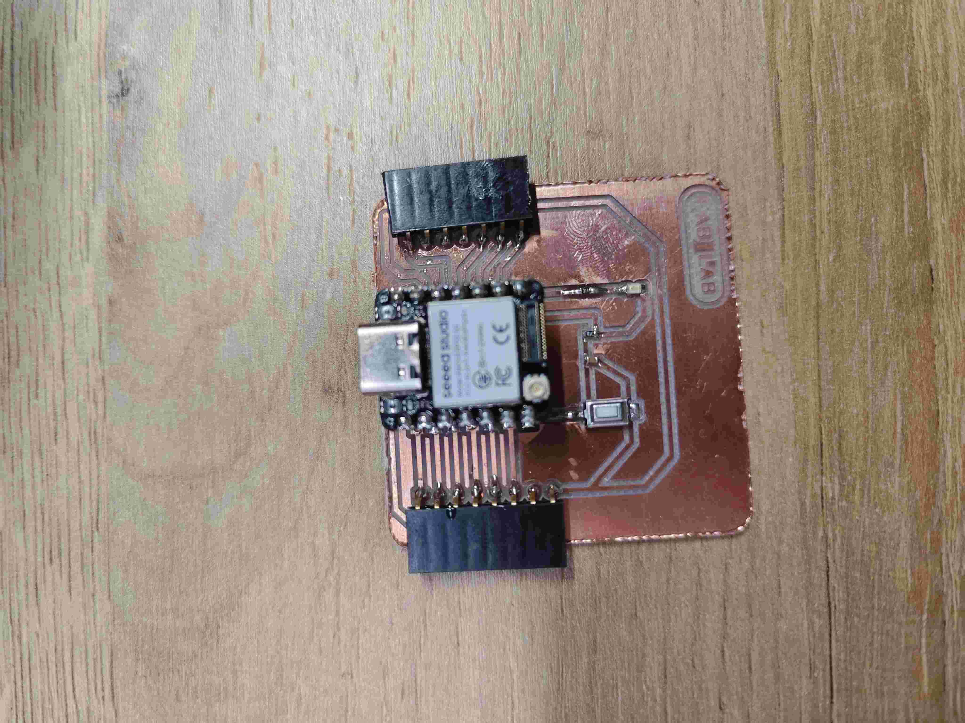
Using a soldering iron, we attach the necessary electronic components to the board. It is important to apply the correct amount of solder to avoid cold joints or bridging between pads.
- Solder small components
- Solder inner components
- Solder outer components
1.7 Function Testing
const int buttonPin = D6; // Button connected to D6
const int ledPin = D7;    // LED connected to D7

void setup() {
    pinMode(buttonPin, INPUT_PULLUP); // Use internal pull-up resistor
    pinMode(ledPin, OUTPUT);
}

void loop() {
    int buttonState = digitalRead(buttonPin);

    if (buttonState == High) { // Button pressed (LOW state)
        digitalWrite(ledPin, HIGH); // Turn off LED
    } else {
        digitalWrite(ledPin, LOW); // Turn on LED
    }
}
When the button is pressed, the LED lights off, verifying the circuit functionality.
1.8 Summary
This week, we completed the entire process from designing to manufacturing an electronic circuit board. By using CNC cutting to fabricate the circuit board and testing its functionality, we successfully verified the feasibility of the CNC cutting process.