0. Group Assignment
This week's group assignment focuses on getting familiar with commonly used electronic measurement tools in the FabLab. These include the multimeter, logic analyzer, and oscilloscope. Understanding how to use these tools effectively is crucial for debugging and testing electronic circuits.
0.1 Multimeter
The multimeter is a versatile tool used to measure various electrical quantities, including voltage, current, and resistance. It is a fundamental instrument in electrical engineering and electronics for troubleshooting and circuit analysis.
Key Functions:
- Voltage measurement: Checking power supply and circuit voltages.
- Current measurement: Measuring current flow in a circuit.
- Resistance measurement: Testing components like resistors and continuity.
For this assignment, I used the multimeter to measure voltage in a circuit:
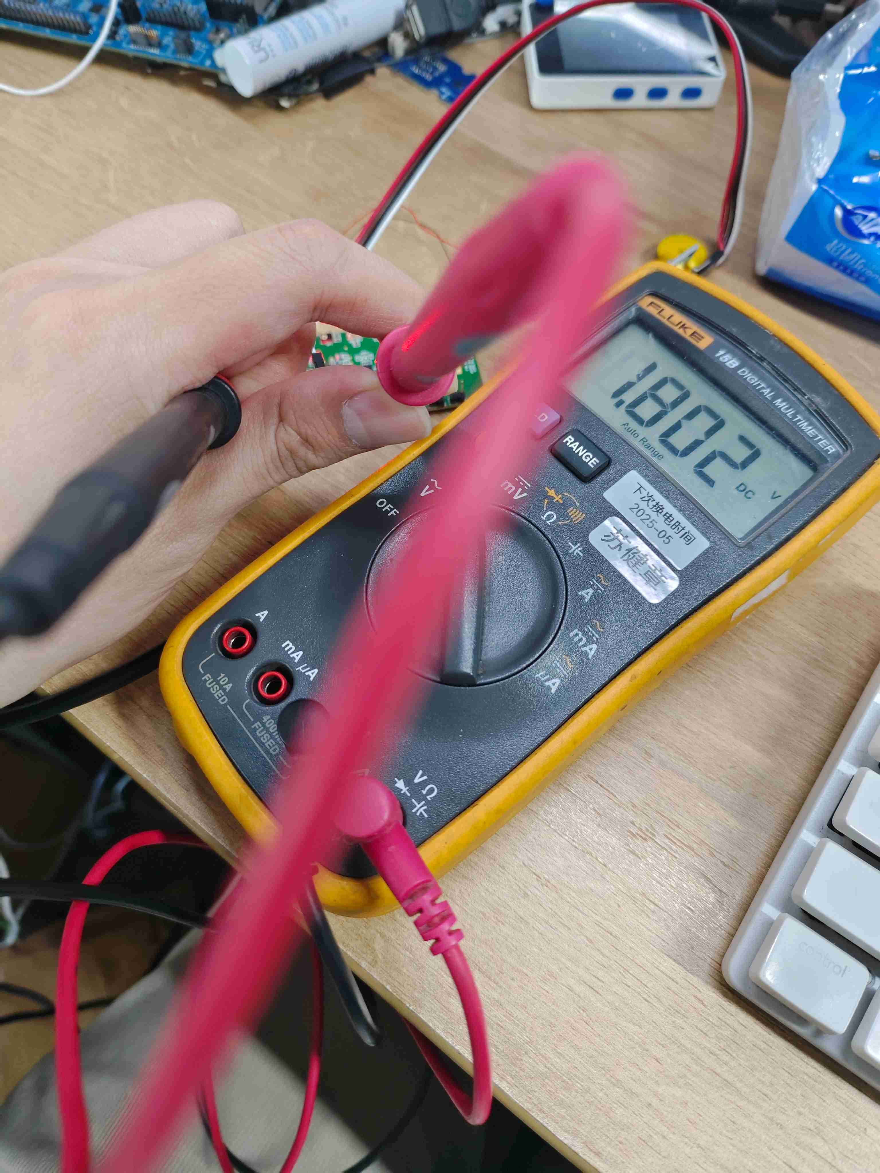
- The measured voltage was 1.8V, which is within the expected range.
0.2 Logic Analyzer
The logic analyzer captures and analyzes digital signals in a circuit. It is commonly used for debugging communication protocols like I2C, SPI, and UART.
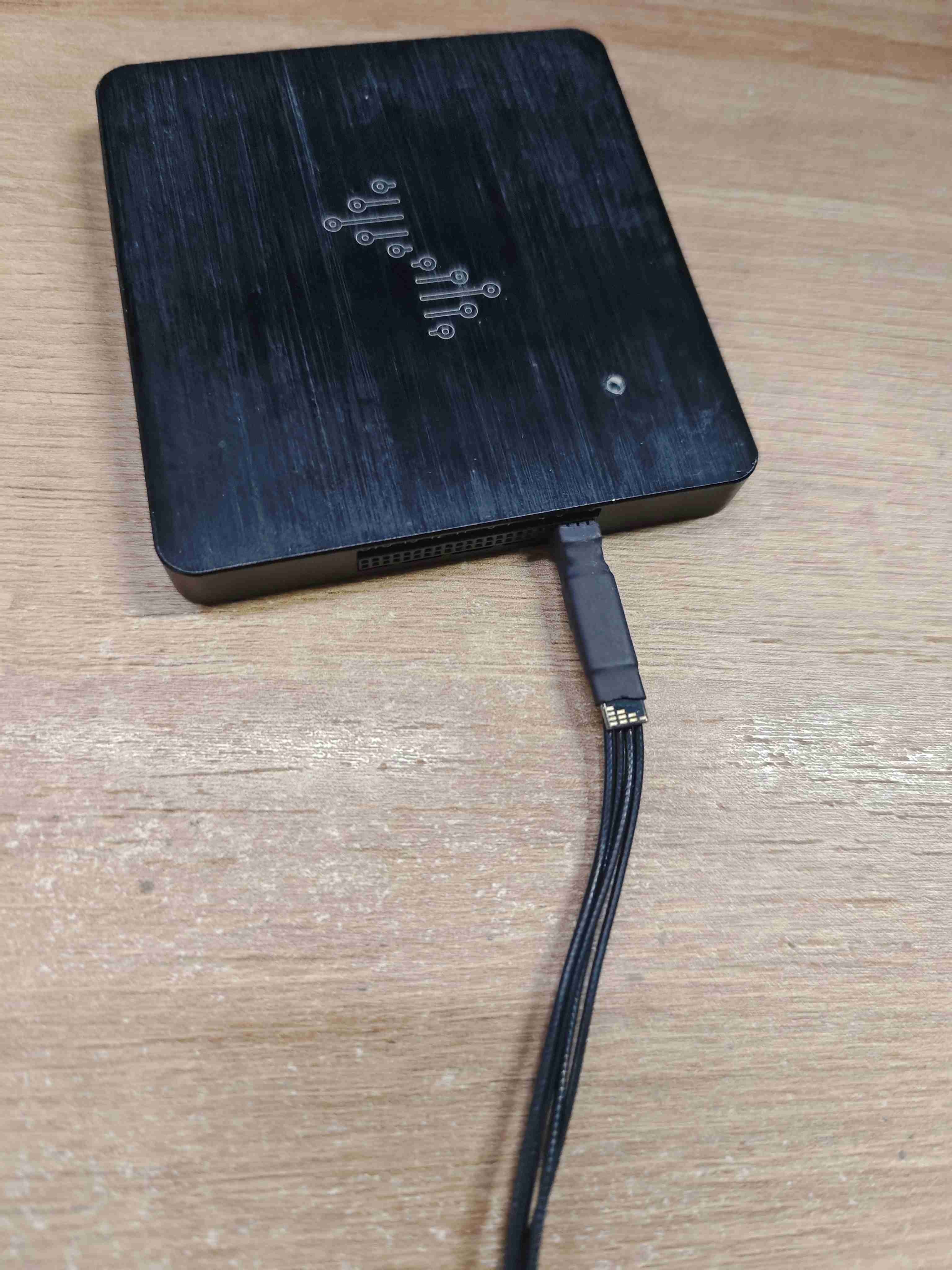
For this task, I used DSLogicPlus to capture and analyze signals.
Steps:
-
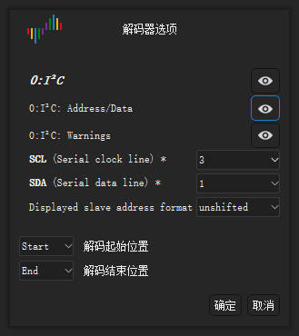
Select the appropriate channel & protocol
-
Configure the signal parameters & start capture
-
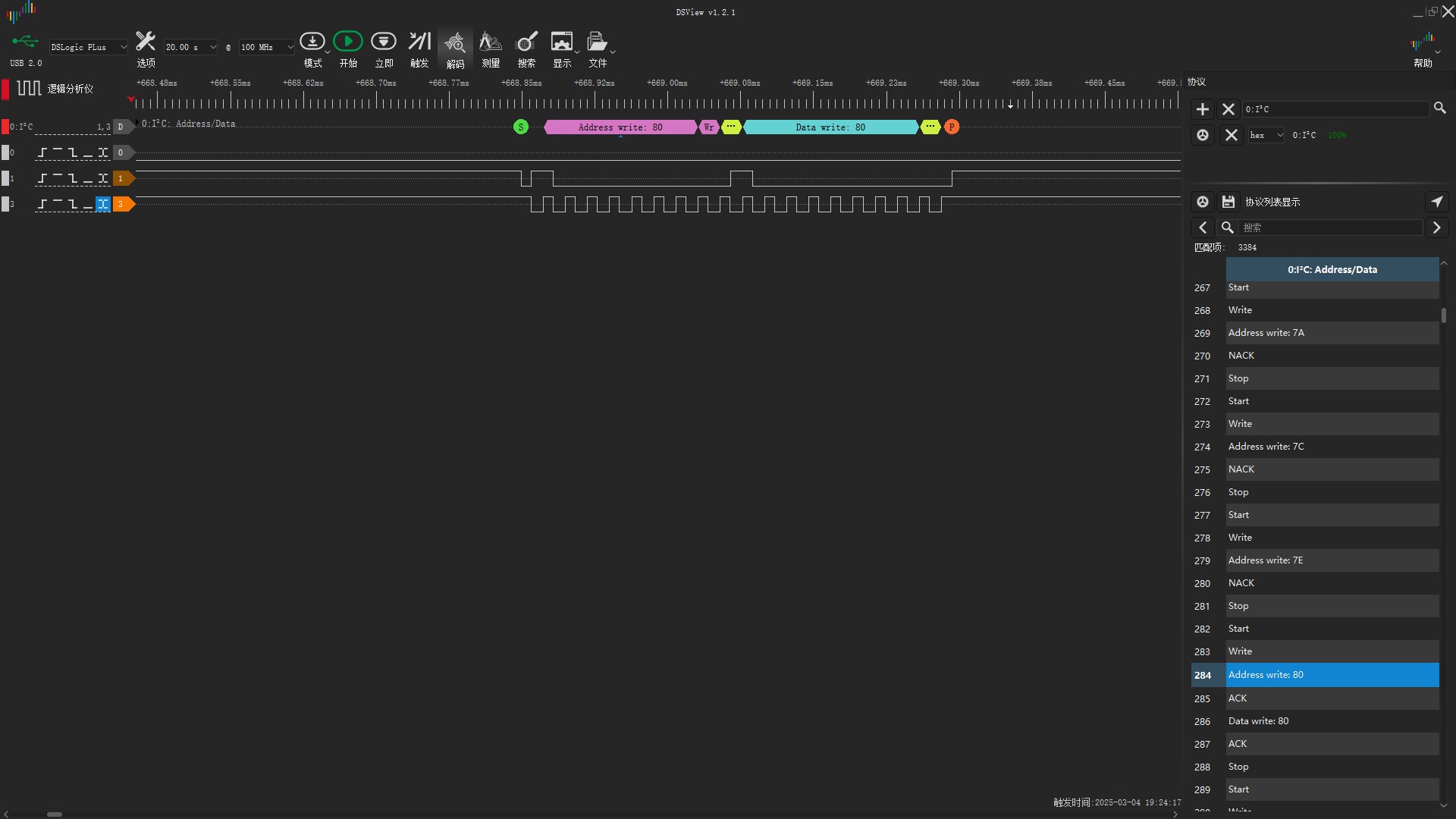
Run an I2C Scan Demo using Arduino
Below is a simple I2C Scanner code to detect connected I2C devices:
#include <Wire.h>
void setup() {
  Serial.begin(115200);
  Wire.begin();
  Serial.println("I2C Scanner");
}
void loop() {
  byte error, address;
  int nDevices;
  Serial.println("Scanning...");
  nDevices = 0;
  for (address = 1; address < 127; address++) {
    Wire.beginTransmission(address);
    error = Wire.endTransmission();
    if (error == 0) {
      Serial.print("I2C device found at address 0x");
    }
  }
  Serial.println("done.");
  delay(5000);
}
-
Analyze the captured signals & frequency
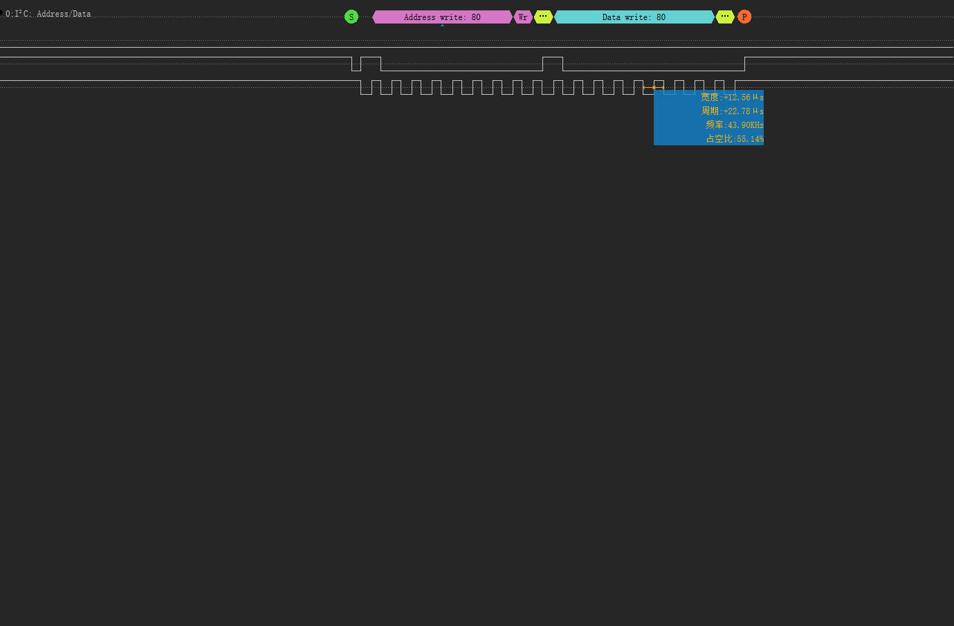
- The SCL signal responded at address 0x80, which is expected since I connected a device with an I2C address of 0x80.
- The detected I2C frequency was 44 kHz, which is lower than the common values of 100 kHz or 400 kHz. This might indicate a configuration issue.
0.3 Oscilloscope
The oscilloscope is used to capture and visualize electrical signals over time. It helps in analyzing signal behavior, identifying noise, and debugging timing issues in circuits.
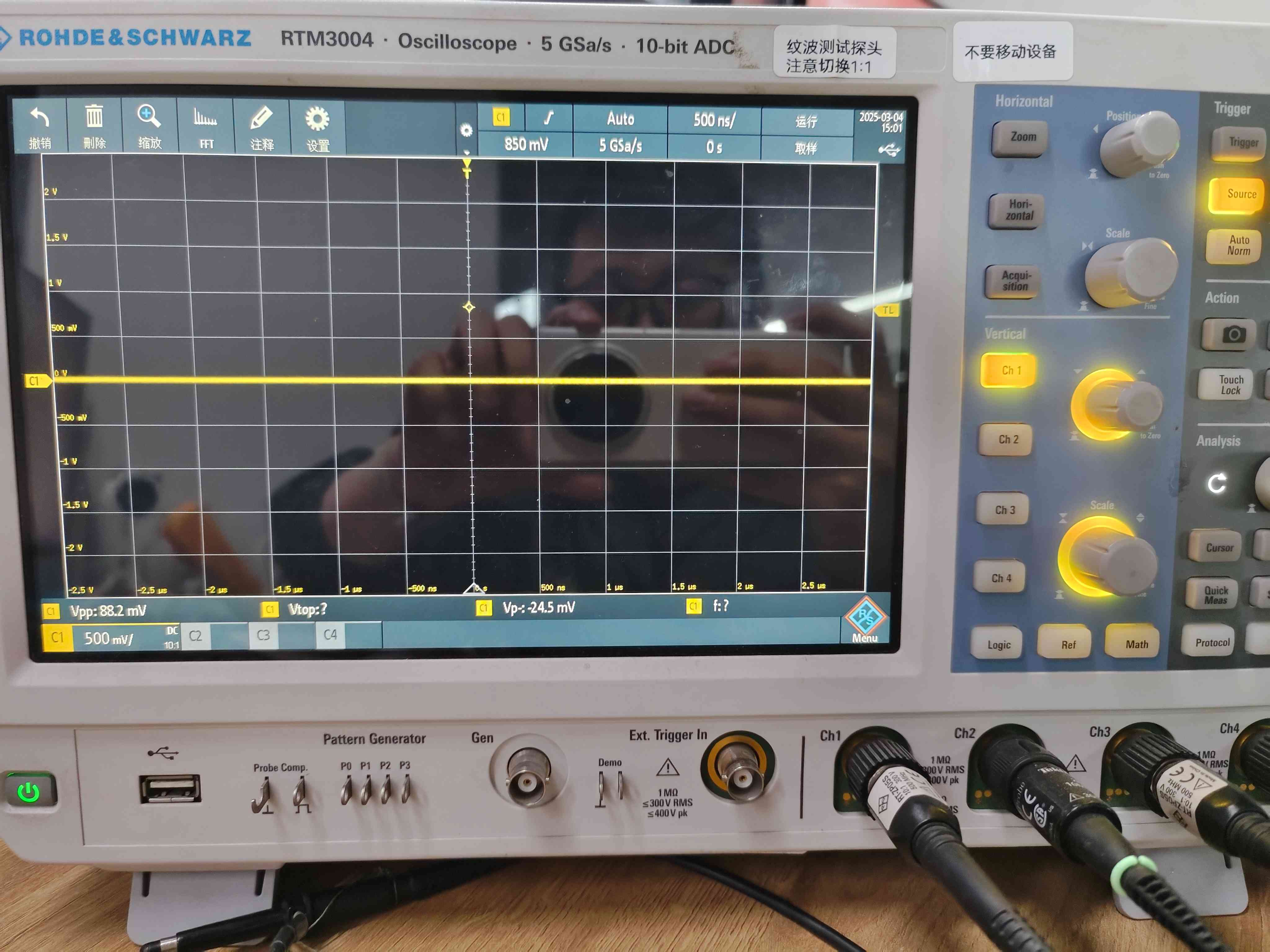
For this assignment, I used the RTM3004 oscilloscope to capture signals.
Steps:
-
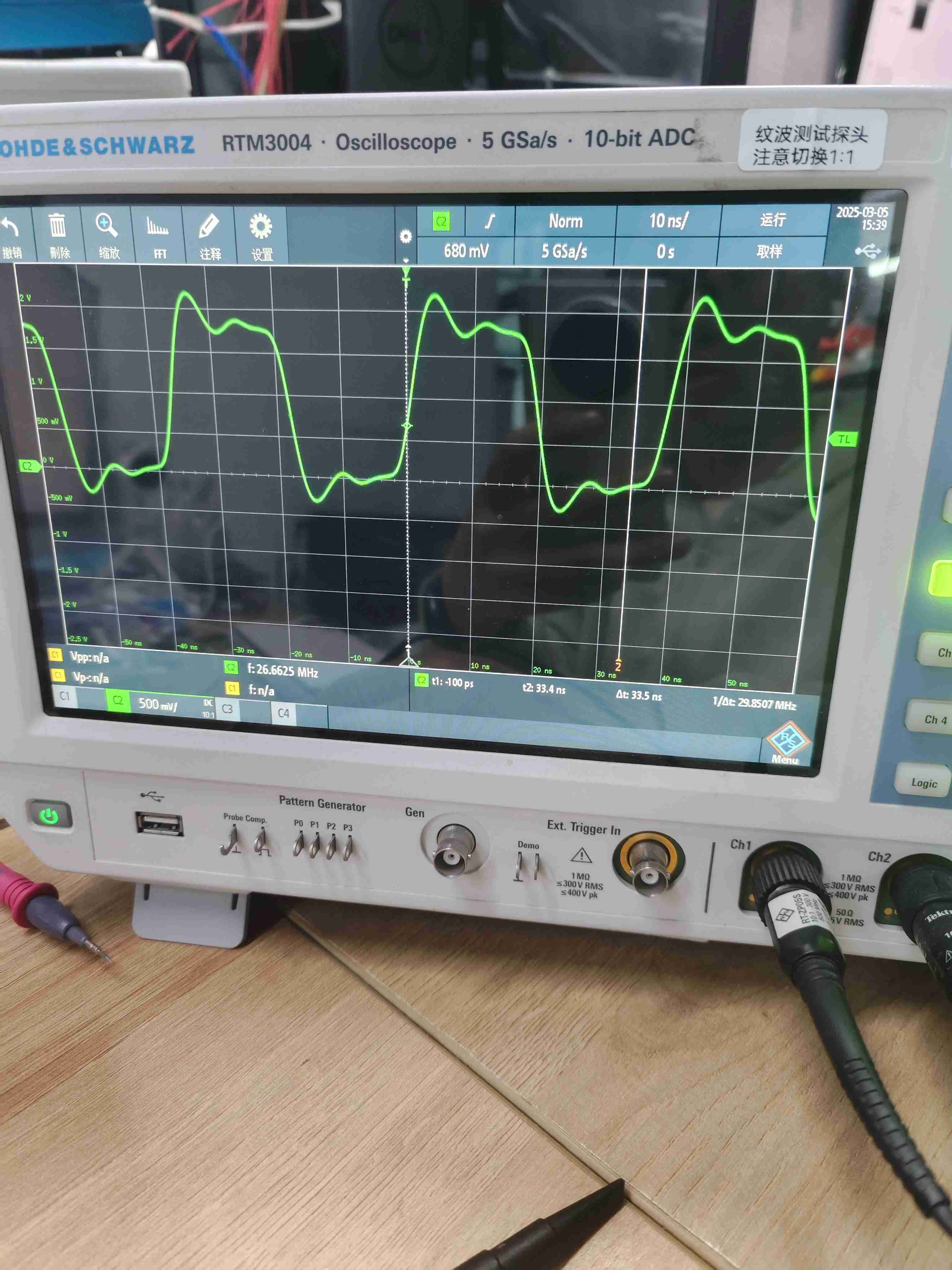
Captured differential frequency signal
-
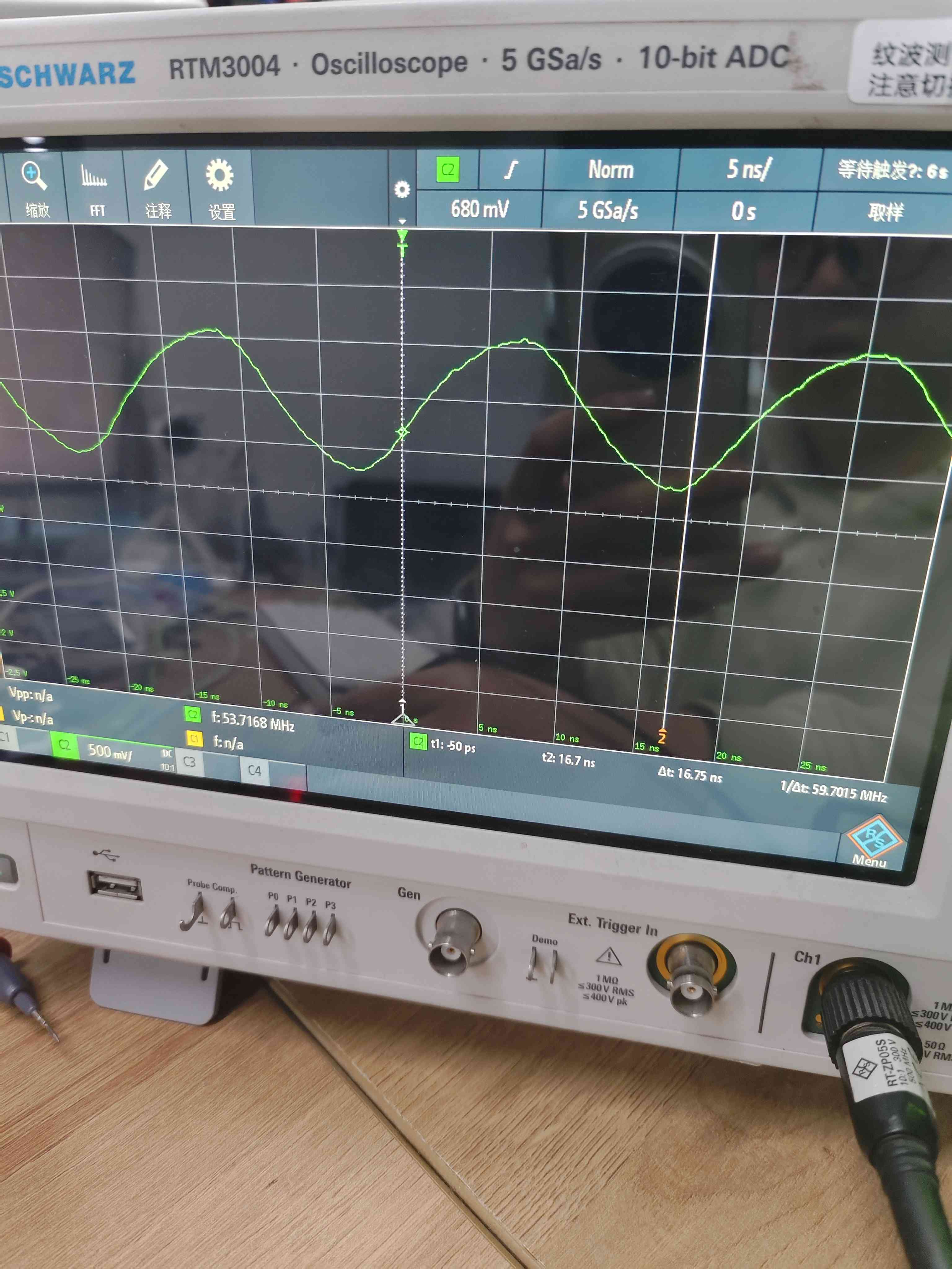
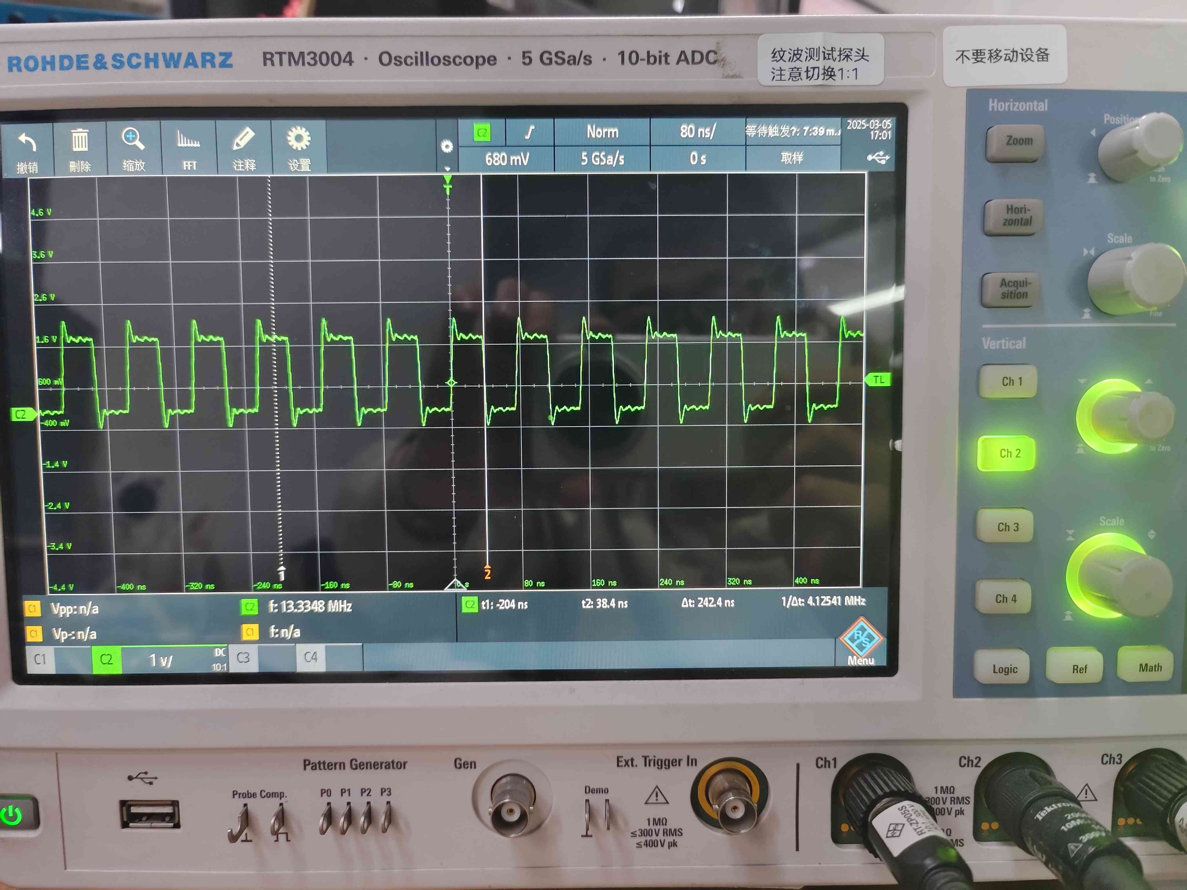
Examined waveform characteristics
-
The oscilloscope models used included 53M, 13M, and 26M.
-
Analyzed I2C clock signal (SCL)
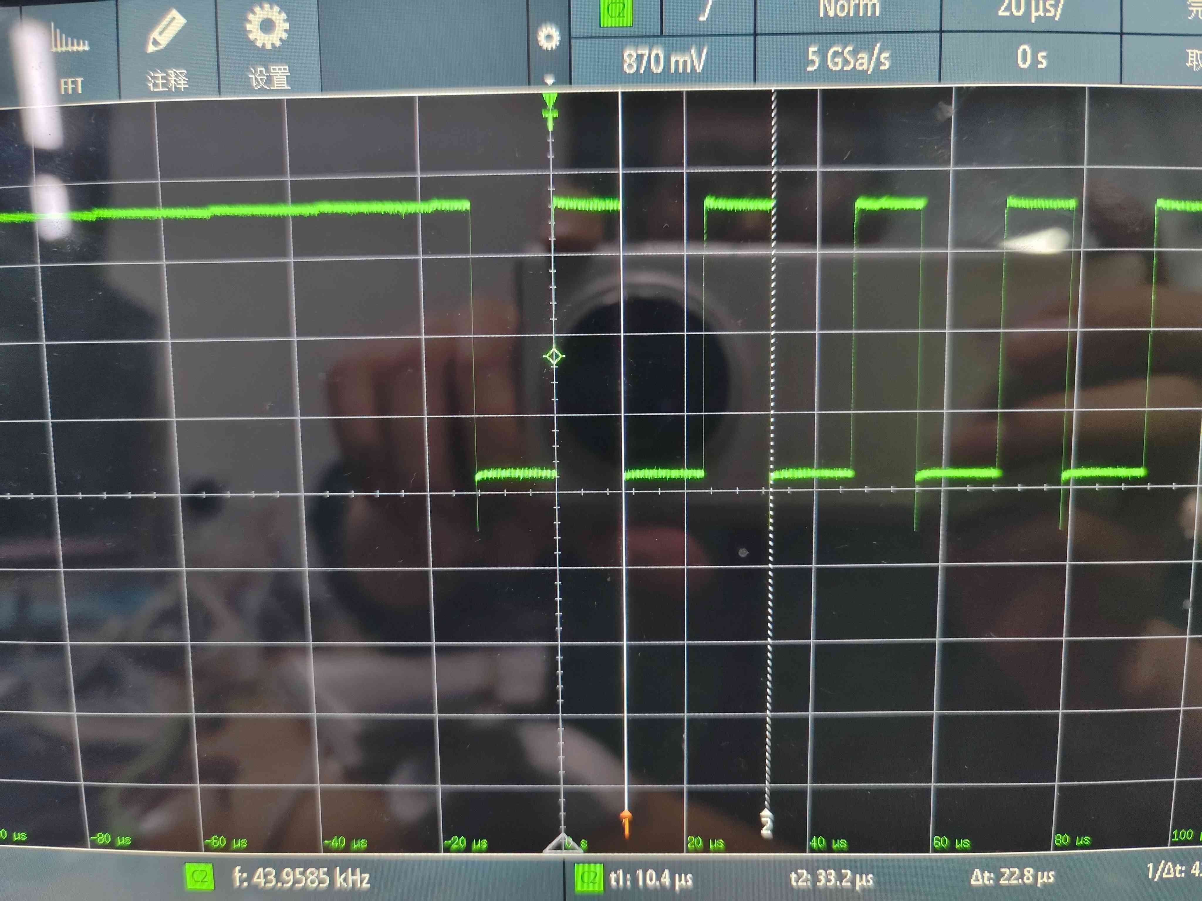
- The I2C CLK frequency was measured at 44 kHz, which is lower than the typical 100 kHz or 400 kHz.
Summary
This group assignment provided hands-on experience with essential electronic measurement tools, including:
- Multimeter for measuring voltage (measured 1.8V, as expected).
- Logic analyzer for debugging digital communication (SCL responded at 0x80, I2C frequency measured at 44 kHz, lower than expected).
- Oscilloscope for visualizing and analyzing signals (I2C CLK measured at 44 kHz, different oscilloscope models tested: 53M, 13M, 26M).
These tools are indispensable for circuit debugging and validation, making them crucial for any electronics-related project. ✅