2. 3D Design Software
There are many 3D design software available, such as:
- Fusion 360:
- Fusion 360 is a professional 3D modeling and design software developed by Autodesk. It offers a range of features for creating, editing, and analyzing 3D designs.
- It is widely used for tasks such as mechanical engineering, architecture, and product design.
- Fusion 360 is available for Windows, macOS, and Linux.
- SolidWorks:
- SolidWorks is a professional 3D modeling and design software developed by Dassault Systèmes. It offers a range of features for creating, editing, and analyzing 3D designs.
- It is widely used for tasks such as mechanical engineering, architecture, and product design.
- SolidWorks is available for Windows, macOS, and Linux.
- FreeCAD:
- FreeCAD is a free and open-source 3D modeling and design software developed by the FreeCAD community. It offers a range of features for creating, editing, and analyzing 3D designs.
- It is widely used for tasks such as mechanical engineering, architecture, and product design.
- FreeCAD is available for Windows, macOS, and Linux.
After comparing these software, I found that FreeCAD is the best choice for my project.
Why I choose FreeCAD? Although Fusion 360 and SolidWorks are also good 3D design software, I choose FreeCAD because it is free and open-source. It is also easy to use and has a wide range of plugins and modules available to extend its capabilities. I am a software engineer, and I was open a lot projects in the past, I love to use open-source software.
FreeCAD is a free and open-source 3D parametric modeler. It is one of the most popular open-source software tools for 3D modeling and engineering design. As a parametric modeler, FreeCAD allows you to define the relationships between objects, making it easier to edit designs by changing parameters. It’s especially useful for product design, mechanical engineering, and architecture. FreeCAD is highly customizable, with a wide range of plugins and modules available to extend its capabilities.
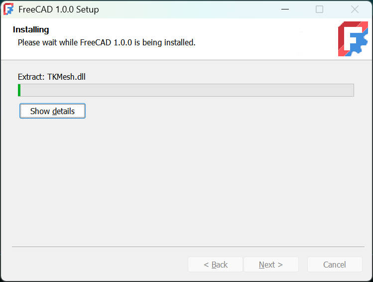
2.1 Installation
To install FreeCAD on your computer, follow these simple steps:
- Go to the FreeCAD website.
- Download the appropriate installer for your operating system (Windows, macOS, or Linux).
- Run the installer and follow the instructions to complete the installation.
In my case, I’ve installed FreeCAD on my Windows computer, and the process was straightforward.
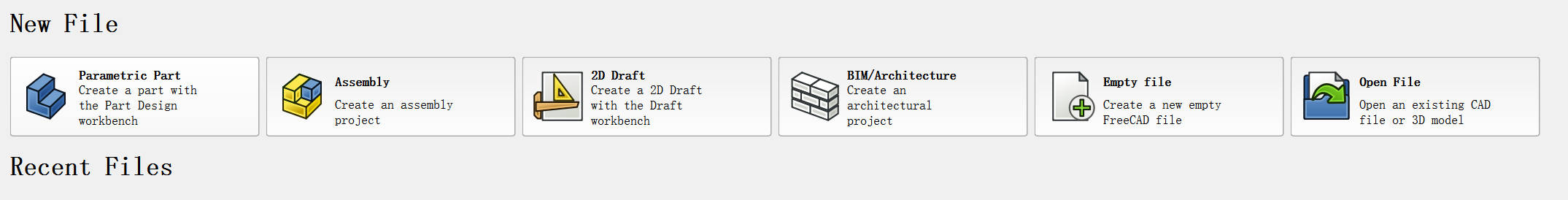
2.2 Getting Started
Once FreeCAD is installed, you can start creating and editing models. FreeCAD operates with a variety of workbenches—each specialized for different tasks, such as part design, sketching, 3D modeling, and more. You can switch between these workbenches based on the task at hand.
2.3 Creating Models
FreeCAD uses a layer-based system to organize your models. Layers are like building blocks in your design, and you can create, delete, and edit them as needed. You can use keyboard shortcuts to quickly create and edit layers:
- Ctrl + N creates a new layer.
- Ctrl + E allows you to edit an existing layer.
Once you are familiar with the interface, you can start working on creating more complex designs by adding different types of objects to your model.
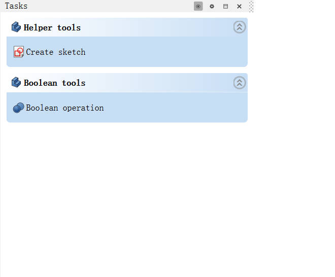
2.4 Creating a Part Design
To start with, let's create a simple part design. A part is a single object in your design that can be modified independently.
2.5 Creating a Sketch
The next step is to create a 2D sketch, which forms the base for the 3D design. A sketch is essential because all 3D models begin with a 2D shape that is then extruded or otherwise transformed into 3D.
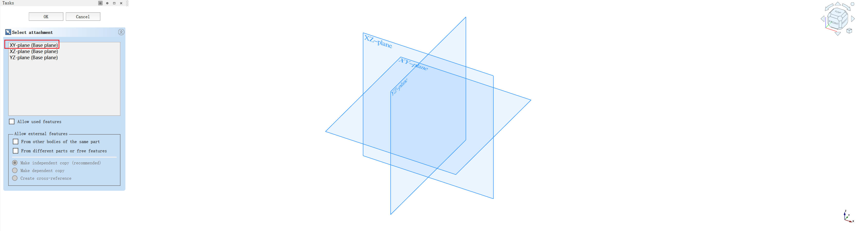
To create a sketch, you first need to choose a plane to draw on. In this case, I selected the XY plane, which is a flat surface that lies along the x and y axes.
Now, you need to decide on the geometry that you want to create. I decided to start with a simple rectangle.
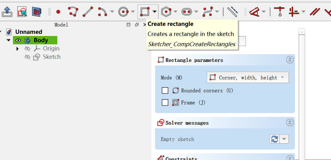
2.6 Creating a Rectangle
Once the plane is selected, you can start drawing your 2D geometry. A rectangle is a common shape used in many designs. In FreeCAD, you can use the Rectangle tool in the Sketcher workbench to easily draw this shape.
2.7 Adding Constraints
Constraints are one of the core features of parametric modeling. They define the relationships between elements in your design and control the dimensions and positions of different parts of the model.
Here, I’ll show you two types of constraints that are commonly used in FreeCAD:
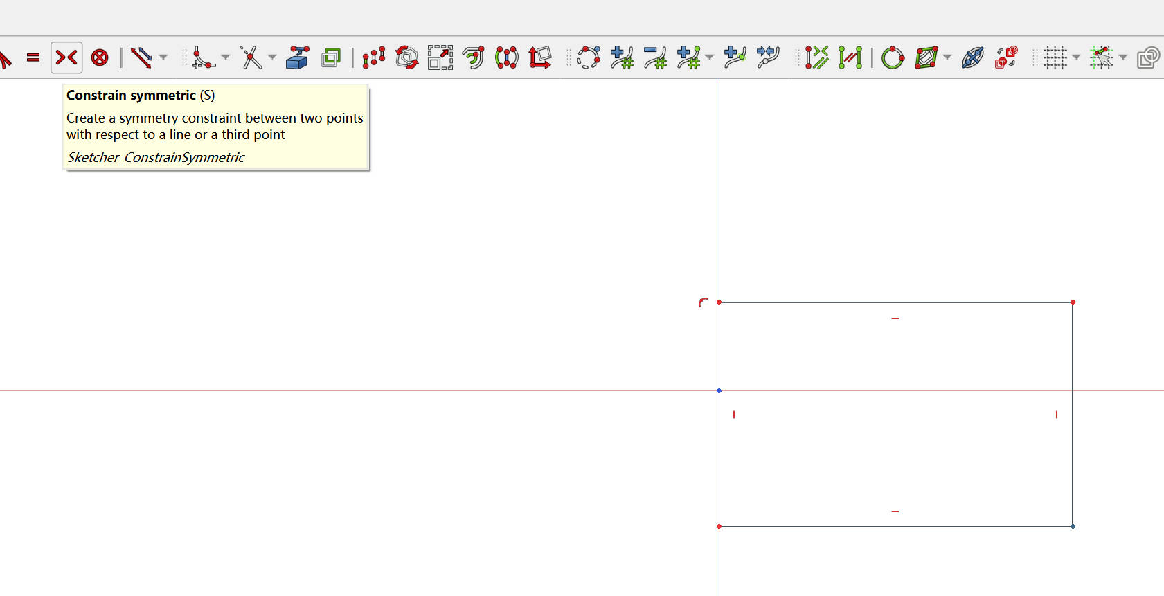
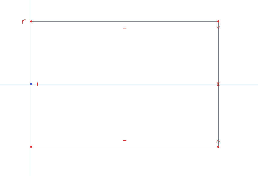
-
Symmetry Constraint: This ensures that two parts of the sketch are symmetric about a line (such as the center line). Symmetry is important in designs that need to be balanced or centered.
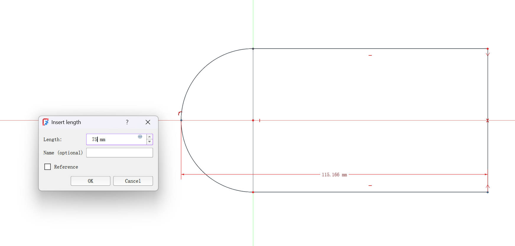
-
Length Constraint: This allows you to specify the exact length of an edge. You can click on an edge and apply a length constraint to define its size precisely.
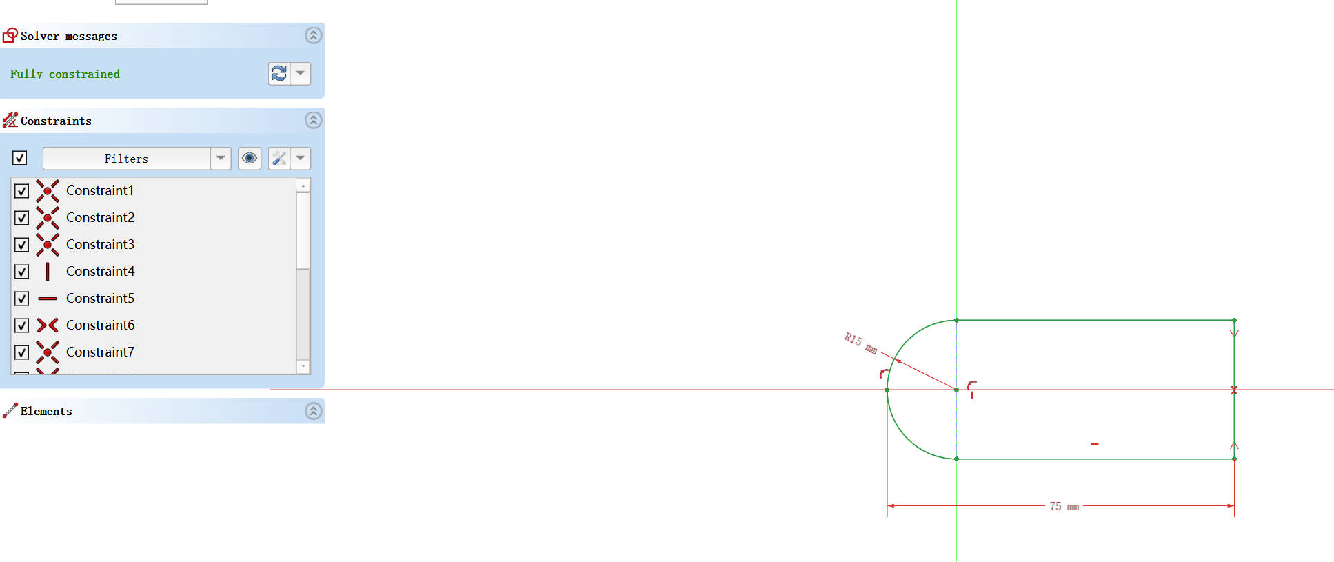
Once you’ve applied all the necessary constraints to your sketch, the next step is to move on to creating the 3D part. Without these constraints, the model wouldn’t be fully defined, and you wouldn’t be able to accurately extrude or modify it.
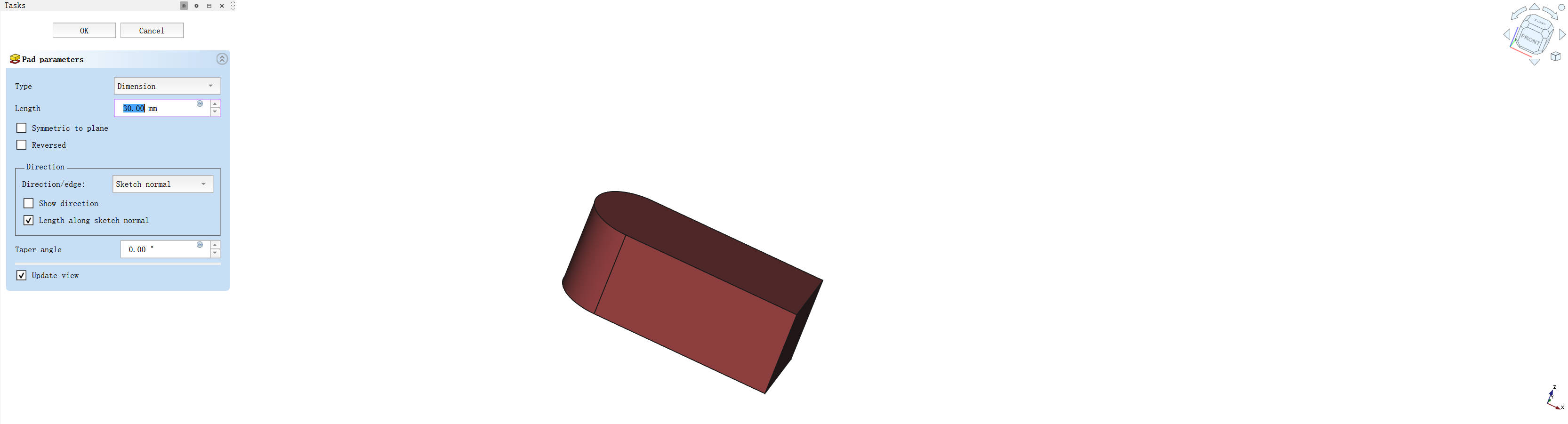
2.8 Creating the 3D Part
After all the constraints are added, you can now proceed to create the 3D part. You can extrude the sketch to add depth or modify it further to form more complex shapes.
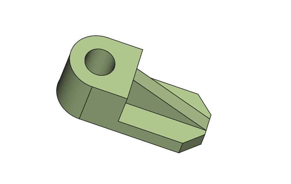
2.9 Finalizing the Design
Once your part is extruded, you can finalize the design by making any last adjustments to its size, shape, or position. You can also apply additional features like fillets or chamfers to smooth out edges or create beveled corners.
Resources
- Design.FCStd: This is the FreeCAD file for the simple part I created in this tutorial. You can download it to explore and make your own changes.