Final Project - RoboBuddy
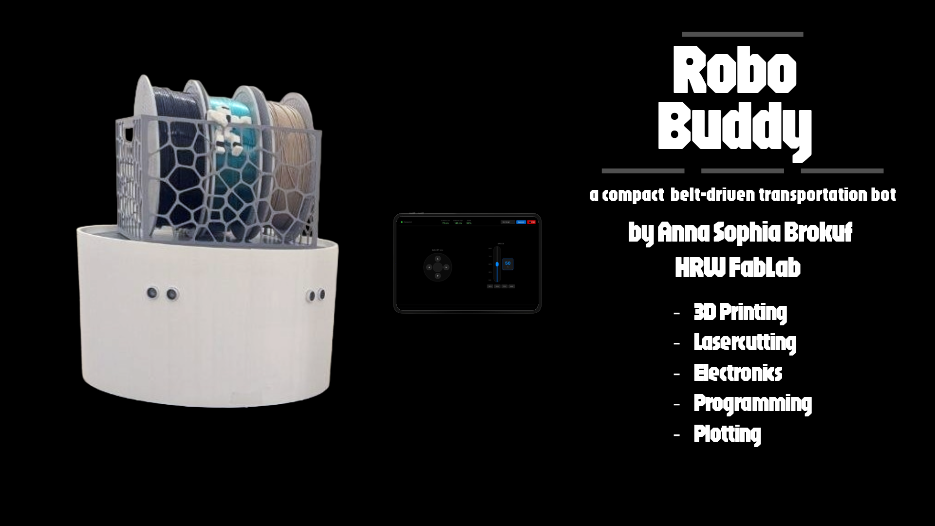
a belt-driven, app-controlled transport robot
Presentation
Progress Overview
| Task | Status |
|---|---|
| Design and 3D print bearing blocks | ✅ |
| Insert ball bearings into bearing blocks | ✅ |
| Manufacture drive wheels with belt pulleys | ✅ |
| Laser-cut top and bottom plates | ✅ |
| Purchase and integrate drive shafts | ✅ |
| Develop first version of control app | ✅ |
| Design and 3D print external casing | ✅ |
| Redesign motor driver PCB | ✅ |
| Redesign ultrasonic sensor PCB (GRV 4-pin) | ✅ |
| Integrate power supply and voltage regulation | ✅ |
| Program a React Native app to control the robot | ✅ |
| Integrate automatic obstacle avoidance | ✅ |
| Film a video of the functionality of the final version of the robot | ✅ |
What does it do?
RoboBuddy is a belt-driven, app-controlled transport robot built entirely from scratch. It uses two NEMA17 stepper motors with a custom belt drive construction for differential steering, controlled wirelessly via a React Native app over WiFi. Two HC-SR04 ultrasonic sensors provide automatic obstacle avoidance, slowing down and steering away when an object is detected, and stopping completely if the distance becomes critical. A 3D-printed basket with a magnetic mount sits on top of the robot and can be snapped on and off for easy loading and unloading of cargo.
Who's done what beforehand?
The idea for RoboBuddy was inspired by the R2D2 Builder Community, a global network of hobbyists who construct life-sized R2D2 replicas from scratch. While differential drive robots are a well-established concept in robotics, this project was developed without referencing existing community approaches or tutorials, the design, construction, and programming were worked out independently from scratch. The method of manufacturing PCBs with a vinyl plotter on FR4 board with copper foil from guitar building supplies is not widely documented and emerged entirely from experimentation during this project.
What did I design?
Everything in RoboBuddy was designed from scratch. On the mechanical side, this includes the bearing blocks modeled in Fusion 360 and 3D-printed, the drive wheels with integrated belt pulleys, the 3D-printed enclosure with snap-in slots and seam, the battery holder, and the magnetic basket. The top and bottom plates were designed in Inkscape and laser-cut from aluminum. On the electronics side, the PCB layouts for the power supply board and the obstacle avoidance and ESP32 controller board were designed from scratch. The TMC2209 motor driver modules were used as off-the-shelf components and integrated into the system. For the firmware running on the ESP32S3, the Arduino libraries WiFi.h and WebServer.h were used to set up the ESP32S3 as a WiFi access point and handle incoming control commands from the app. The TMC2209 motor drivers were configured based on their official datasheet. The HC-SR04 distance calculation is based on the standard formula: (duration × speed of sound) / 2. All other code was written from scratch without referencing external tutorials or libraries.
What sources did I use?
During development, various datasheets and official documentation were consulted. For the stepper motor drivers, both the DRV8825 official documentation (used during the prototyping phase) and the TMC2209 datasheet were referenced for correct wiring and configuration. The XIAO ESP32S3 pinout and official Seeed Studio documentation were used for pin assignments and peripheral configuration. The HC-SR04 datasheet provided the timing specifications needed for the distance measurement implementation. As mentioned above I used the libraries WiFi.h and WebServer.h for the firmware. For the power supply circuit, a YouTube tutorial was referenced that explained the use of the LM7805 voltage regulator in combination with a TIP3055 transistor and smoothing capacitors for stable 5V output under load.
What materials and components and processes were used?
Parts made:
-
3D-printed parts: bearing blocks, drive wheels, enclosure, battery holder, basket (PLA, FDM)
-
Laser-cut parts: top and bottom aluminum plates (metal laser cutter)
-
Custom PCBs: motor driver board, power supply board, ESP32 controller and obstacle avoidance board (vinyl plotter on FR4 with copper foil)
Processes used:
-
3D printing (FDM, PLA)
-
2D design and laser cutting (metal)
-
PCB design and manufacturing (vinyl plotter, hand soldering SMD components)
-
Embedded programming (ESP32S3, Arduino framework)
-
App development (React Native)
-
System integration (modular PCB tower, JST/Dupont wiring, battery enclosure)
See BOM for further information on the used components.
Where did they come from? / How much did they cost?
Bill of Materials (BOM)
| # | Article | Qty | Source | Price (€) | Shop | Notes |
|---|---|---|---|---|---|---|
| 1 | Copper-clad PCB / FR4 Plates | 2 | Lab Stock | 0 | ||
| 2 | Aluminum plate (chassis) | 1 | Lab Stock | 0 | ||
| 3 | Steel rod 6mm (wheel axle) | 1 | Lab Stock | 0 | ||
| 4 | PLA Filament | ~1000g | Lab Stock | 0 | ||
| 5 | Self-adhesive copper foil (2000x300x0.07mm) | 1 | Lab Stock | 0 | ||
| 6 | XIAO ESP32-S3 Plus | 1 | Reichelt | 9,99 | Shop | |
| 7 | Joy It Nema17 Stepper Motor | 2 | Reichelt | 42,40 | Shop | |
| 8 | TMC2209 BigTree v1.3 | 2 | roboter-bausatz.de | 13,56 | Shop | |
| 9 | DRV8825 (soldered) | 2 | Reichelt | 15,90 | Shop | obsolete |
| 10 | HC-SR04 Ultrasonic Sensor | 2 | Reichelt | 6,90 | Shop | |
| 11 | Hacker LiFe Akku 4100mAh 5S | 1 | flashrc.com | 169,90 | Shop | |
| 12 | Timing Belt | 2 | Z24 | 22,96 | Shop | |
| 13 | Timing Belt Pulley | 2 | Z24 | 28,60 | Shop | |
| 14 | Ball Bearings | 4 | Z24 | 7,60 | Shop | |
| 15 | Rod (6mm) | 2 | Z24 | 21,82 | Shop | |
| 16 | 8-Pin 2.54mm Header (Female SMD) | 4 | Reichelt | 2,60 | Shop | |
| 17 | 2-Pin Connector (Female SMD 90°) | 10 | Reichelt | 5,20 | Shop | |
| 18 | 4-Pin Connector (Female SMD) | 8 | Reichelt | 6,80 | Shop | |
| 19 | 2-Wire Cable (M-M) | 5 | Eckstein-Shop | 5,95 | Shop | |
| 20 | 4-Wire Cable with 2.54mm Jumper (Male) | 2 | Reichelt | 5,98 | Shop | |
| 21 | Ribbon Cable | 1 | Reichelt | 3,10 | Shop | |
| 22 | Male Dupont Connectors (crimping set) | 8 | Reichelt | 9,75 | Shop | |
| 23 | Diode 1N4007 | 2 | Reichelt | 0,06 | Shop | |
| 24 | TIP3055 Transistor | 1 | Reichelt | 2,99 | Shop | |
| 25 | LM7805 Voltage Regulator | 1 | Reichelt | 1,40 | Shop | |
| 26 | Capacitor 10uF 50V | 1 | Reichelt | 0,46 | Shop | |
| 27 | Capacitor 1000uF 25V | 1 | Reichelt | 0,38 | Shop | |
| 28 | Capacitor 100uF | 2 | Reichelt | 0,50 | Shop | |
| 29 | Resistor 220 Ohm | 4 | Reichelt | 0,28 | Shop | |
| 30 | Power Switch | 1 | Reichelt | 1,60 | Shop | |
| 31 | Screws, nuts, spacers | - | Hornbach | 20,00 | ||
| 32 | Black Spray Paint | 1 | Hornbach | 9,90 | Shop | |
| 33 | JST PH CKB | 50 | Reichelt | 2,50 | Shop | |
| 34 | JST PH2P BU | 30 | Reichelt | 1,50 | Shop | |
| 35 | JST PH4P BU | 20 | Reichelt | 1,00 | Shop | |
| 36 | Wheel | 2 | eBay | 6,50 | Shop | |
| 37 | Multi-Wheel (360°) | 1 | eBay | 2,40 | Shop | |
| 38 | Rod 10mm × 180mm | 3 | Z24 | 19,06 | Shop |
Total: 478,59€
License
This project is licensed under CC BY-NC-SA 4.0. You are free to share and adapt this work for non-commercial purposes, as long as you give appropriate credit and distribute your contributions under the same license.

What worked? What didn't?
What worked:
-
The vinyl plotter PCB manufacturing method worked surprisingly well once the copper foil was applied directly to the FR4 board instead of being cut separately
-
The TMC2209 stepper drivers performed excellently
-
The differential drive and belt construction proved to be reliable and robust
-
The WiFi control via React Native app is responsive with no noticeable lag
-
The magnetic basket concept works well in practice and makes loading and unloading intuitive
-
The obstacle avoidance runs smoothly: the robot slows down and steers away cleanly before stopping if necessary
What didn't work / needed iteration:
-
The DRV8825 motor drivers were replaced by the TMC2209 due to volume and connectivity issues
-
The copper foil peeled off the backing film when plotted directly, which required the workaround of applying it to the FR4 first
-
Next time I wouldn't use SMD connectors on plotted PCB as they are very fragile
-
The 5V sensor supply required a design revision after the first prototype revealed the sensors couldn't run on 3.3V
What questions were answered?
Several questions were answered during the development of RoboBuddy. The most important one was whether it is feasible to manufacture functional PCBs at home using a vinyl plotter, copper foil, and FR4 board. The answer is yes, with the right settings, preparation and caution while soldering. Another question was whether the TMC2209 drivers would be a viable replacement for the DRV8825. They proved to be significantly quieter, easier to configure and more reliable. It was also confirmed that a React Native app can communicate reliably with an ESP32S3 access point in real time with no noticeable lag, making it a practical approach for wireless robot control.
How was it evaluated?
RoboBuddy was evaluated in several stages. First, the motors were tested individually without the app, driven directly through the firmware to verify correct wiring and direction. Next, both motors were tested together with the full circuit on a breadboard, still without the app, to confirm coordinated movement. Once the basic mechanics were verified, the app control was added and tested.
Obstacle avoidance was tested using a half-open door as an obstacle. The robot successfully managed to navigate through the gap into the room on the second iteration. First it revealed that the intervention distance was set too short. The threshold at which the robot starts steering away and reducing speed was increased accordingly until the avoidance behavior was reliable
What are the implications?
RoboBuddy demonstrates that a fully functional, app-controlled robot can be built at home using a combination of digital fabrication tools and off-the-shelf components at a reasonable cost. The vinyl plotter PCB manufacturing method in particular has broader implications. It offers a accessible and low-cost alternative to milling or ordering PCBs, requiring only a vinyl plotter, copper foil and FR4 board. The modular PCB tower design makes the platform easy to maintain and extend and the path recording and playback feature already implemented in the firmware opens the door to semi-autonomous operation without expensive additional hardware. With the addition of a LIDAR sensor, the platform could serve as a base for more advanced autonomous navigation experiments.
Linked Weeks
Weeks in which I worked on the final project:
- Week 2 – Computer-Aided Design
- Week 4 – Embedded Programming
- Week 9 – Input Devices
- Week 10 – Output Devices
- Week 14 – Interface and Application Programming
- Week 15 – System Integration
- Week 16 – Wildcard Week
Acknowledgements
Special thanks to my instructors Lars Mattern and Jonas van Hagen for their guidance, support, and patience throughout the Fab Academy.
Initial Concept
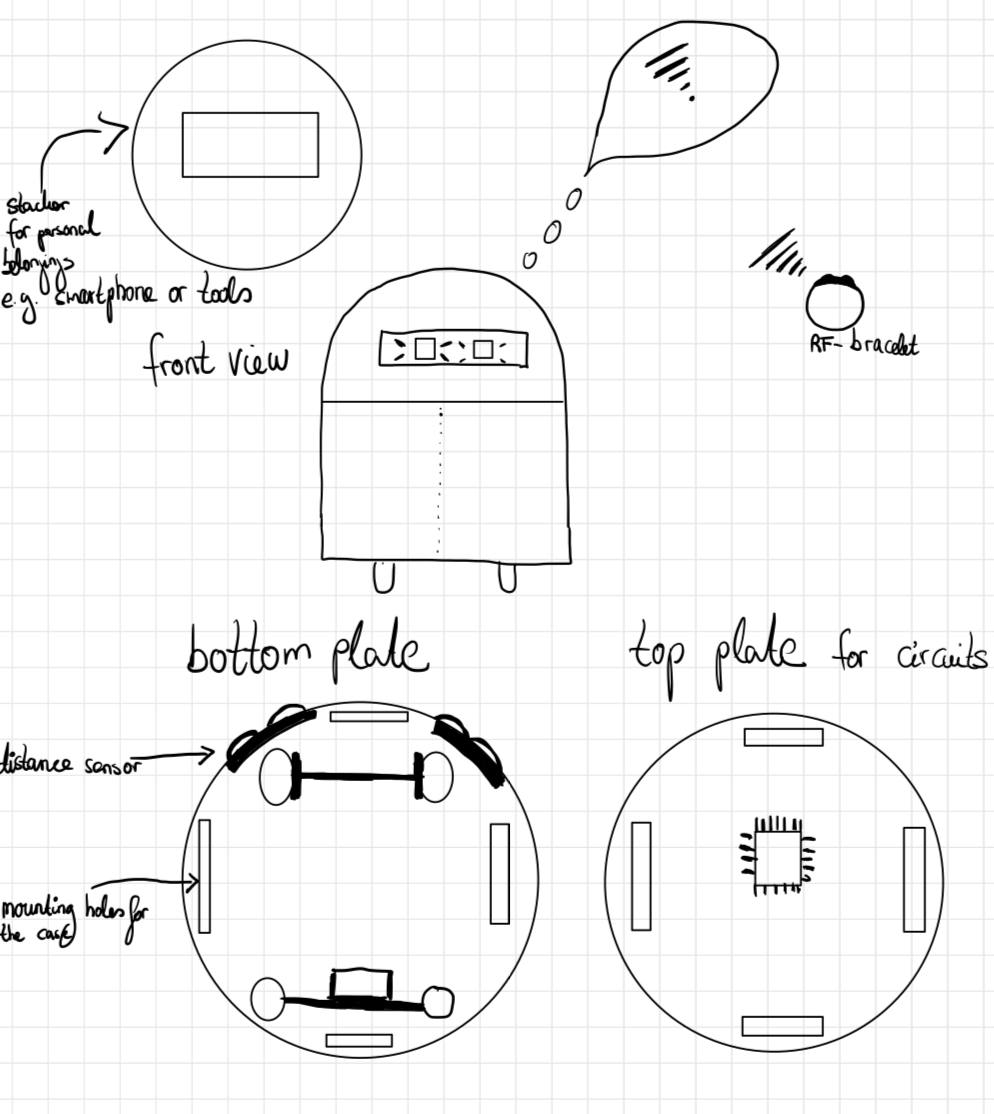
Inspired by R2D2 builders, the idea for this project was to create a robo-assistant that carries belongings and integrates with smart controls. The concept evolved into a compact transport robot with wireless app control and obstacle detection. As the time of the Fab Academy is limited, I concentrated on building a reliable, self-contained robot that can be driven manually and transport a payload with autonomous features planned for future development.
First Draft
I started with a rough sketch to visualize my project.
Spiral Development Plan
The development of RoboBuddy is structured in iterative stages, each one delivering a working prototype and building toward the final functionality.
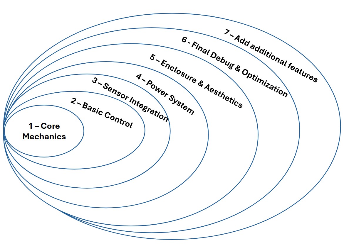
- Spiral 1 – Core Mechanics: Assembly of chassis, drive shafts, wheels, and bearing blocks. Ensure stable movement and structural integration.
- Spiral 2 – Basic Control: Implement remote control functionality using the smartphone app. Test basic movement: forward, backward, turn.
- Spiral 3 – Sensor Integration: Add and test obstacle detection using ultrasonic sensors using I2C between boards.
- Spiral 4 – Power System: Add final power supply, including voltage regulation and battery integration. Test full mobility.
- Spiral 5 – Enclosure & Aesthetics: 3D model and print the robot shell and integrate the dome, mounting slots, and covers.
- Spiral 6 – Final Debug & Optimization: Refine PCBs, clean wiring, stress-test interaction between modules, and prepare final documentation.
- Spiral 7 – Path Recording & Playback: Implement route recording and replay functionality for semi-autonomous navigation.
Modeling
2D-Modeling
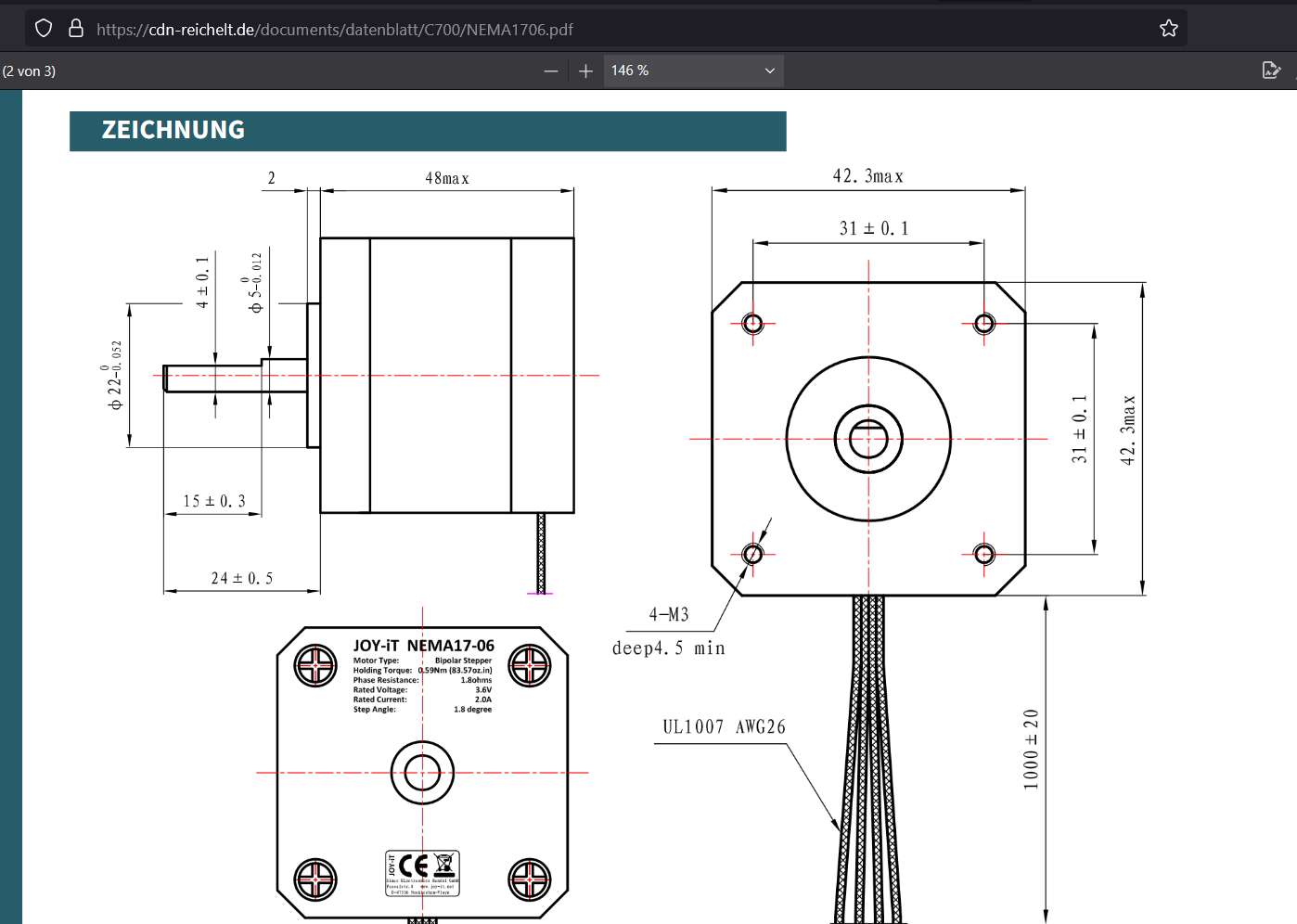
One way to produce the bearing blocks for the drive of my final project is to design them in 2D and cut them out with the metal laser cutter. For this reason, I will first model the bearing blocks in Inkscape. For my final project, I need two bearing blocks, which accommodate a 13mm ball bearing and connect the two shafts to each other via a toothed belt. I therefore need a bearing block to which the stepper motor is attached and the drive shaft for the tires, as well as a counterpart that receives the drive shaft.
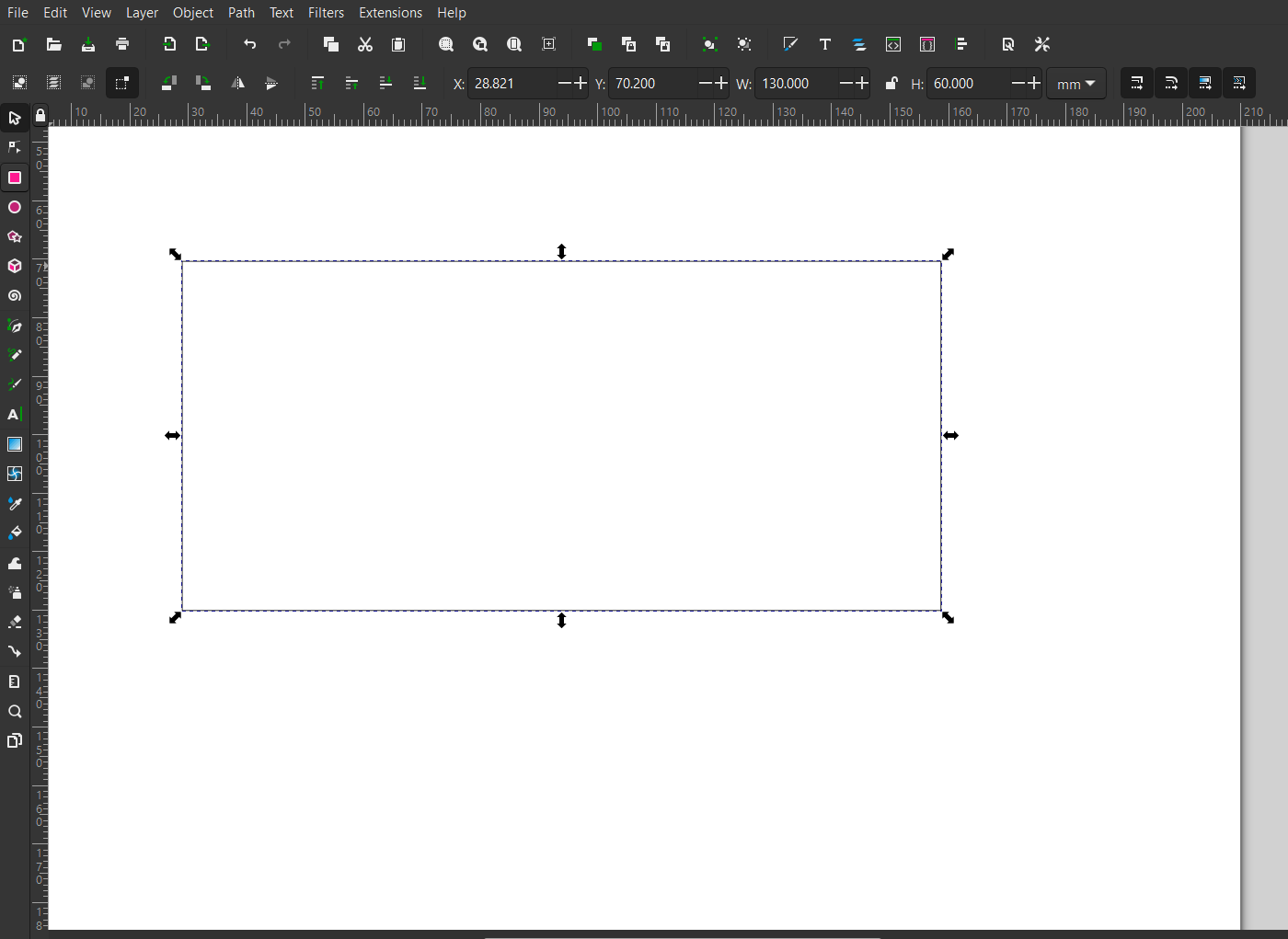
The dimensions should be 130mm x 60mm. I also need two recesses. One for the ball bearing and one for the motor shaft.
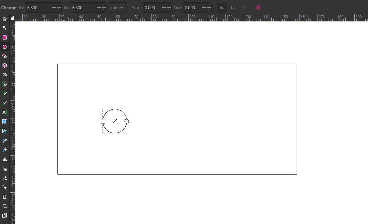
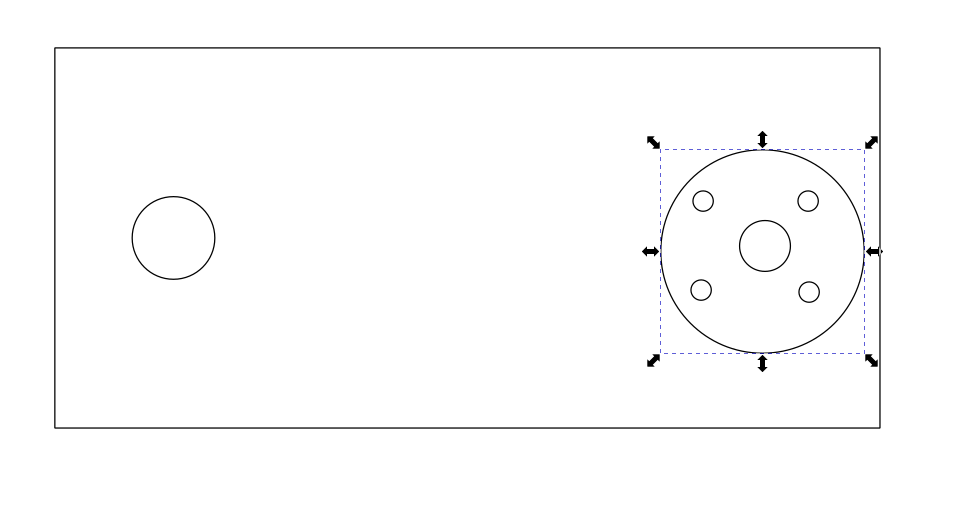
After I have drawn the first circle and entered the dimensions 6.5 mm radius Rx and Ry at the top, I draw the second circle with the diameter of the drive shaft. The Nema17 stepper motor has an outer shaft diameter of 8mm.
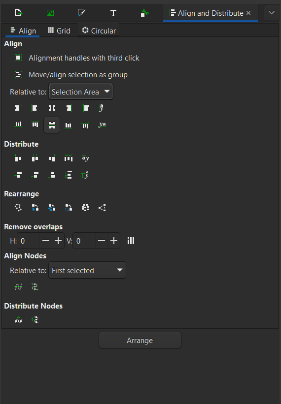
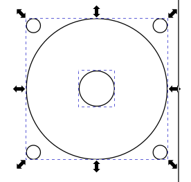
Next, I want to center the circles. To do this, I first mark all the elements.
Next, I use the align tool and select center on horizontal axis.
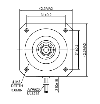
Now the holes with which the motor block is attached are still missing. The frame size of the Nema17 is 42mmx42mm. In the data sheet I found out that the distance between the screw holes is 31mm.
In addition, M3 is used for the screws. I looked in the ISO thread table DIN 13, T1 and found that the through hole for an M3 fine thread is 3.2mm. So I draw 4 holes with the corresponding dimensions.
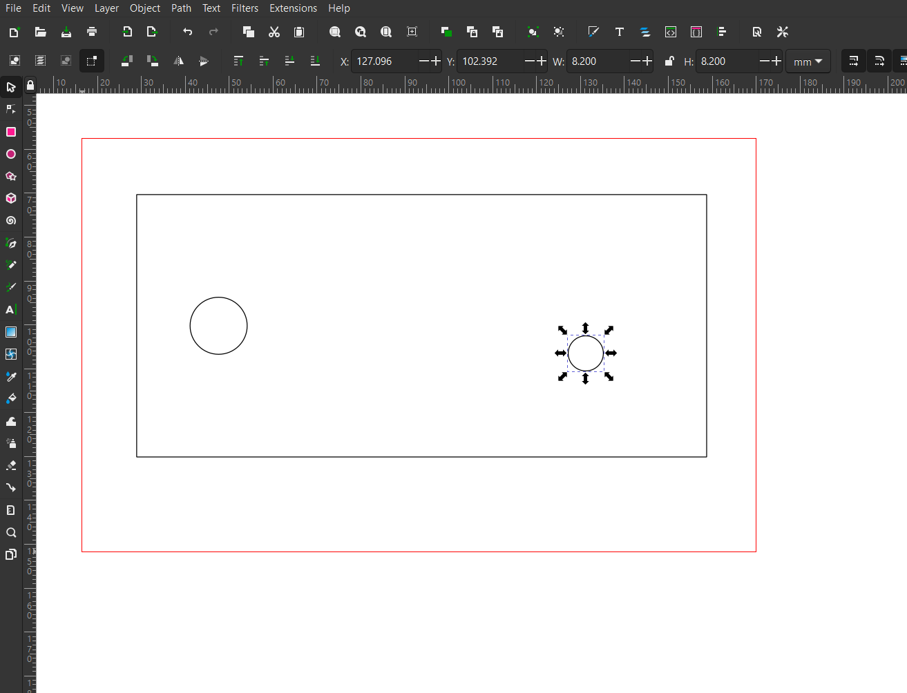
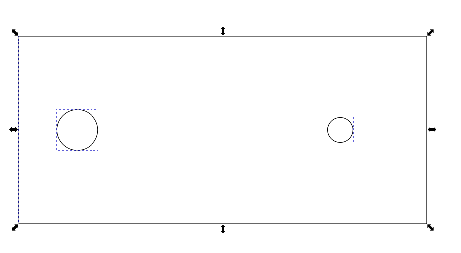
Next, I draw a circle with a diameter of 32mm around the elements for orientation.
The distribution tool helps to distribute the through holes accordingly on the auxiliary circle. Next, the circle that we needed to distribute the objects is deleted.
I group the elements so that they can no longer move in the future. A little hint: Unlike most programs, Inkscape uses Shift to select multiple objects.
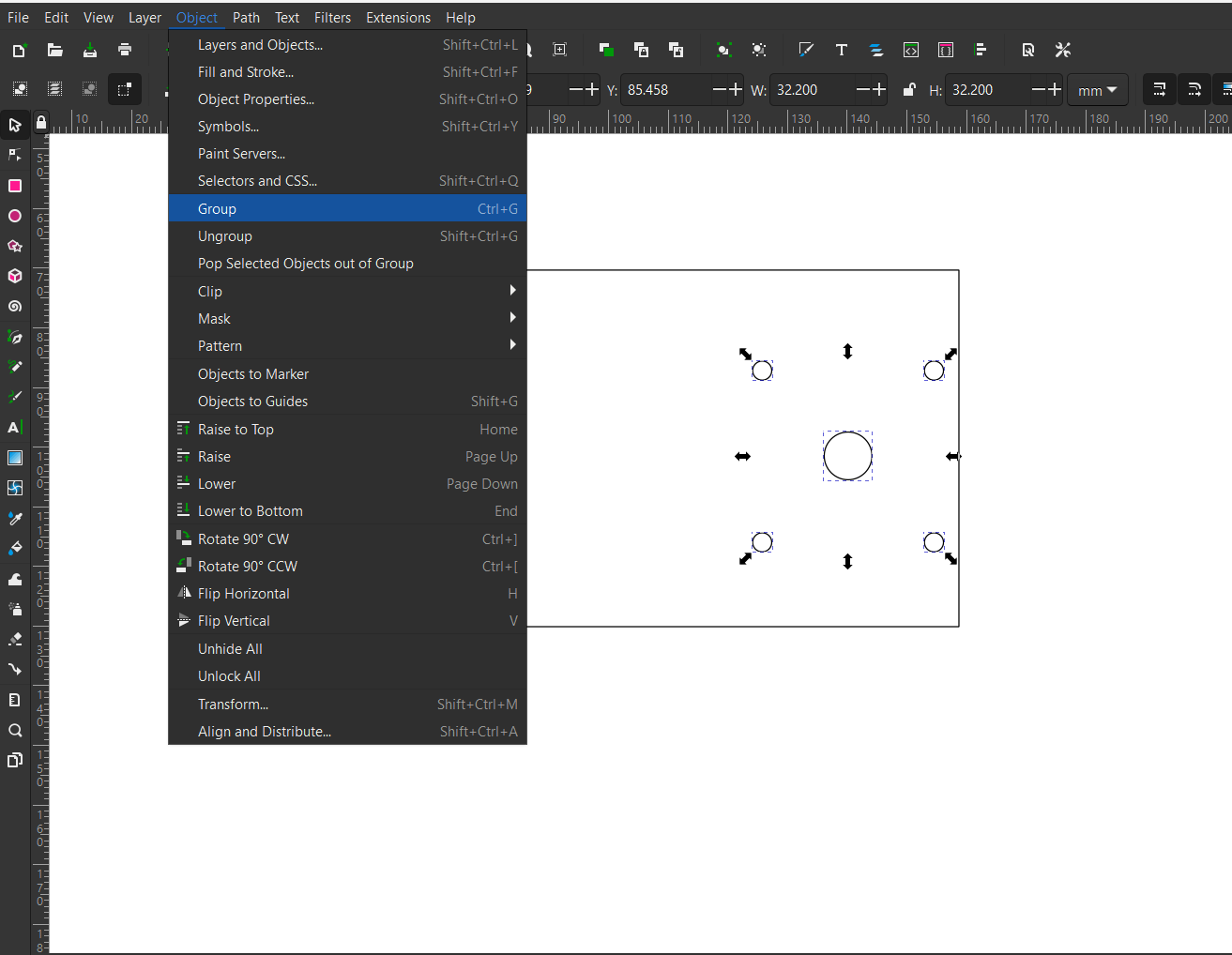
When drawing, I noticed the error that the motor should not float in the middle of the bearing block, but must be placed at the bottom. So I move the group and save the file as .svg.
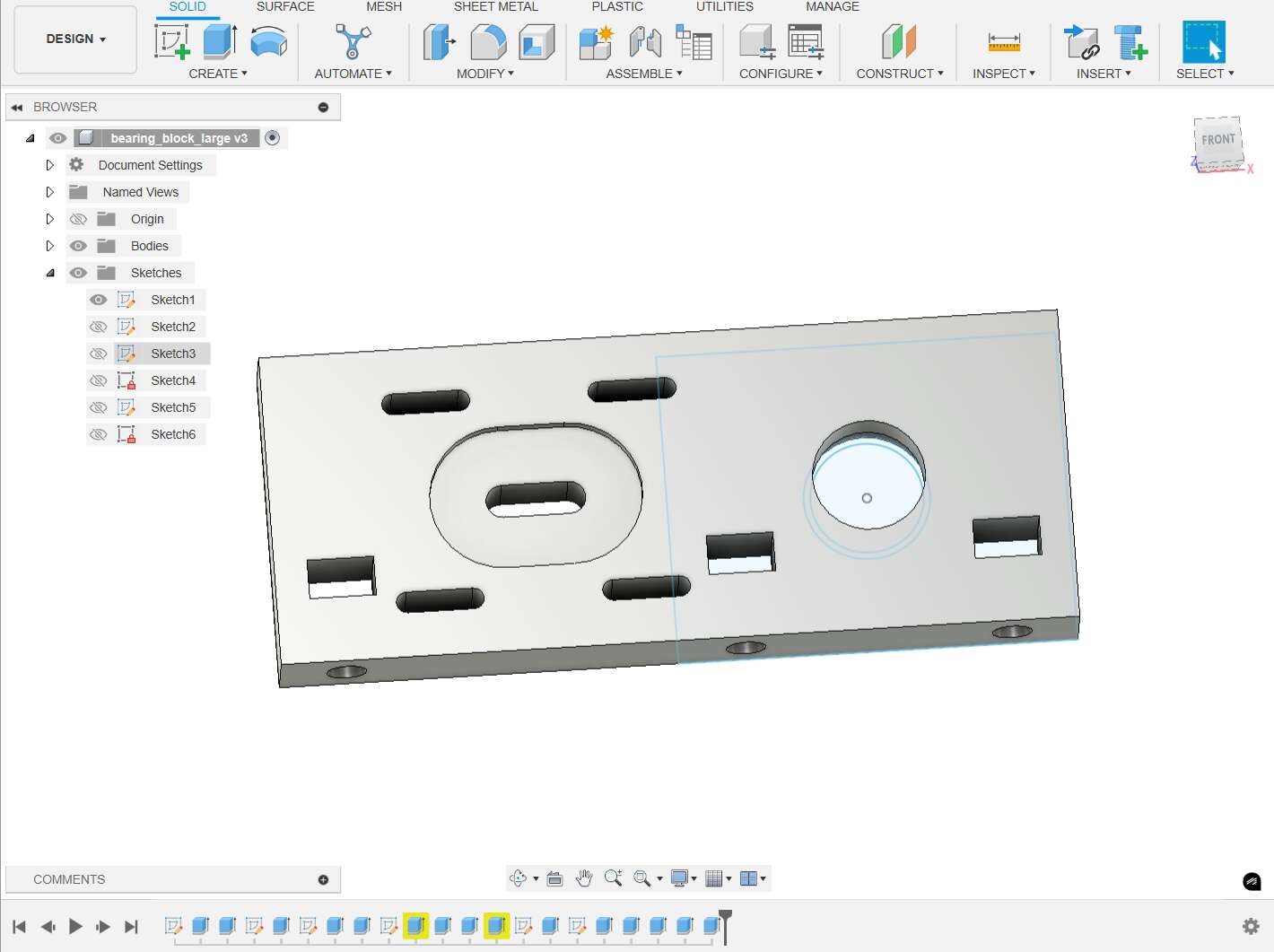
3D-Modeling
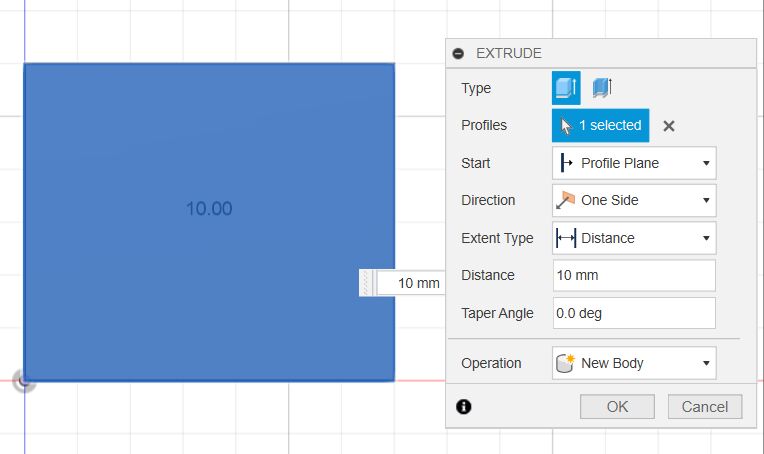
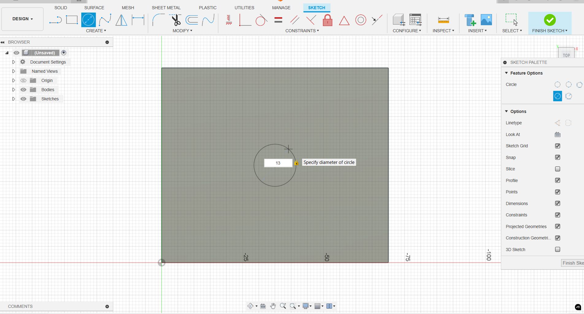
Next, I modeled the second bearing block in Fusion 360 3D. This has the advantage that I can simply print it out for testing and don't have to use so much aluminum for the first prototypes. I start by creating a sketch in Fusion and create a square measuring 600 mm x 700 mm.
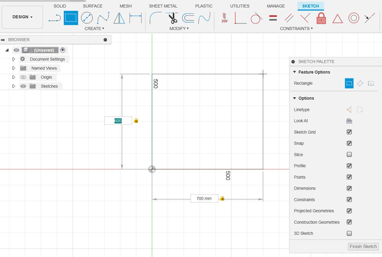
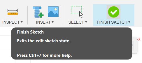
Next, I press Finish Sketch to finish the sketch.
Then I extrude the cuboid.
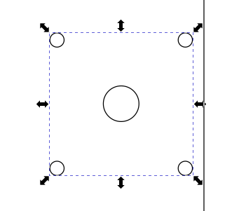
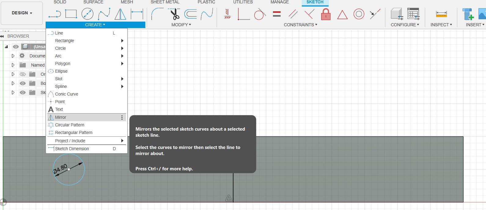
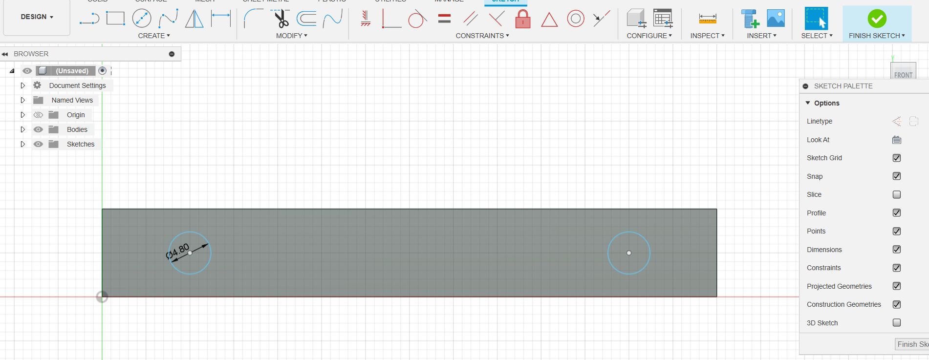
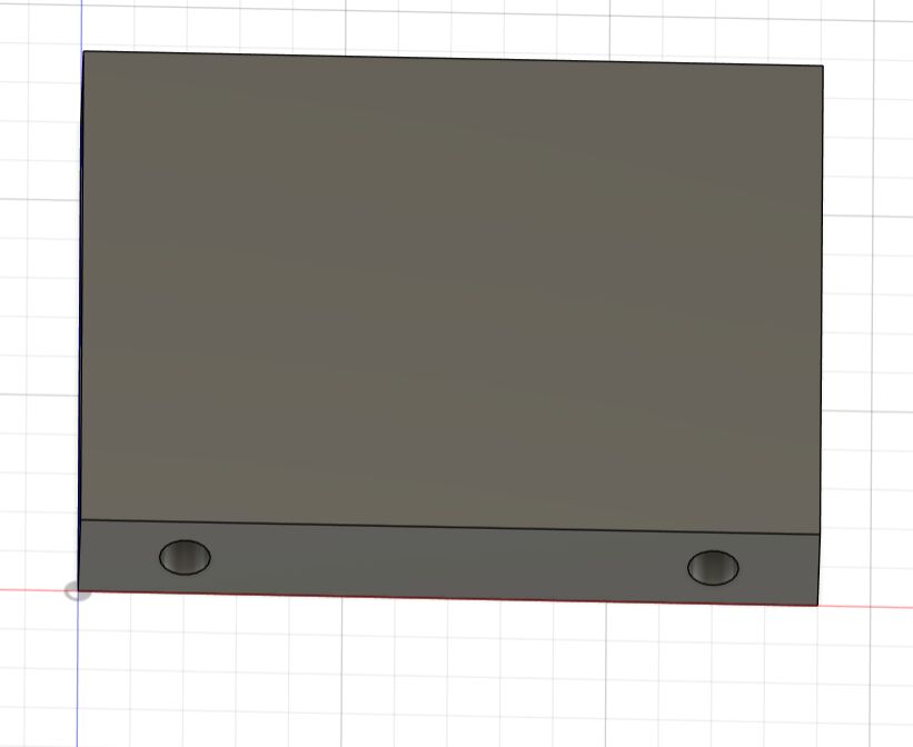
The next step is to model the drill holes in the lower part of the block. To do this, I switch back to the sketch view, select the underside of the block as the basis and draw a guide line in the middle. I create a circle and would now like to have it on both sides of the block, which is why I mirror it on the auxiliary line.
After removing the auxiliary line, it looks like this.
Then I finish the sketch again and cut out the drill holes with the Extrude tool at a depth of 15mm.
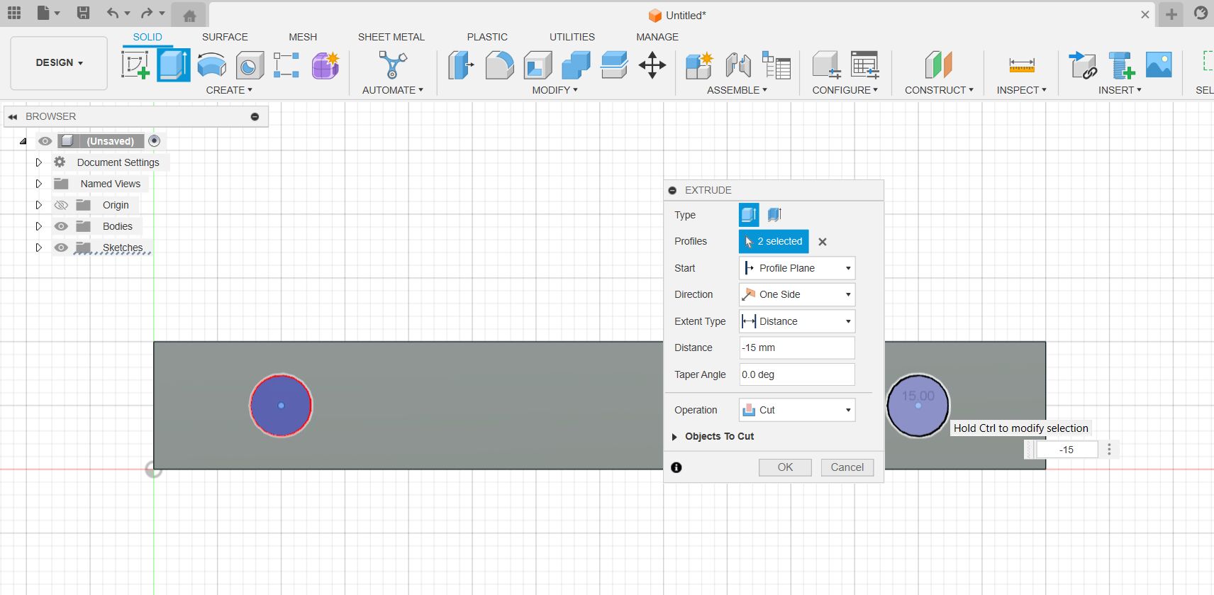
The model then looks like this:
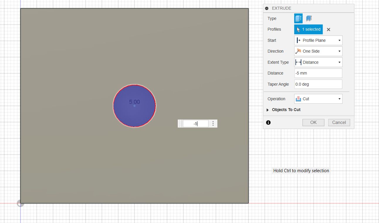
Next, we take care of the recess for the ball bearing. Since the ball bearing only has a depth of 5mm and we have a material thickness of 10mm, we have to draw a circle with 13mm and drill 5mm deep.
We want to leave a margin of 2mm. To do this, we select the same center point and draw a circle with a diameter of 11mm, which we then drill through to the full thickness of the material.
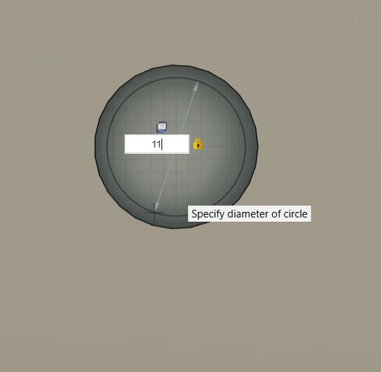
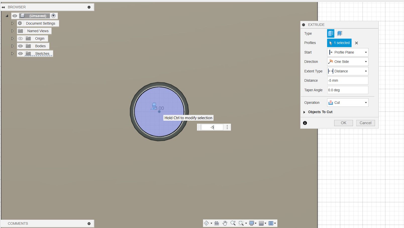
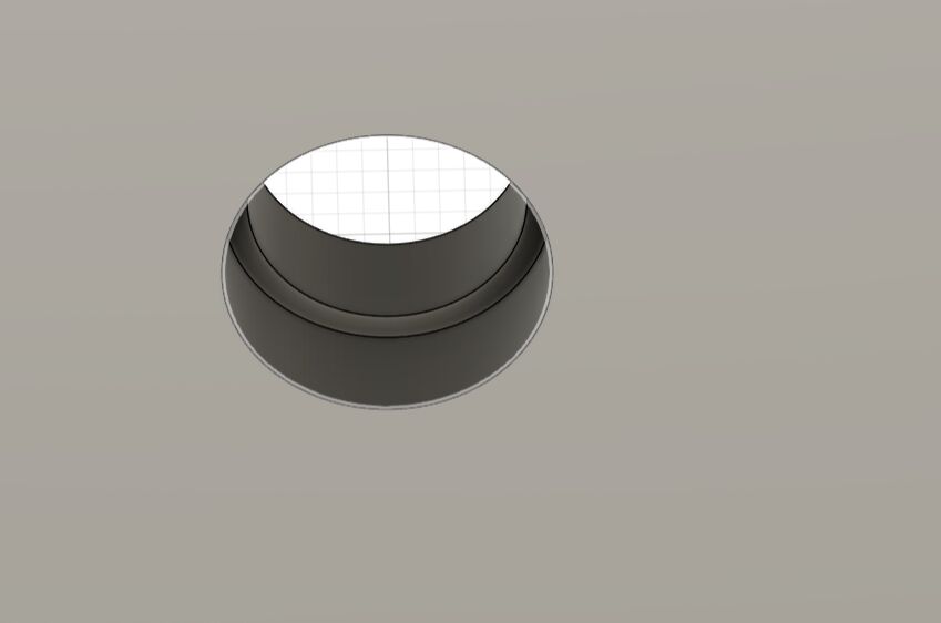
Our model for the bearing block is finished.
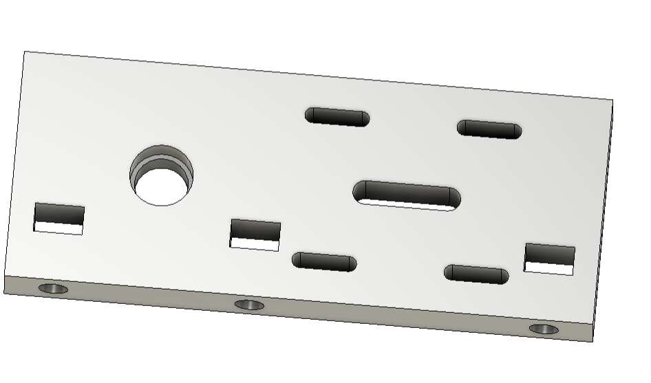
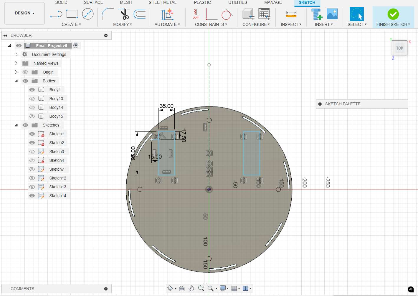
3D modeling of the final project
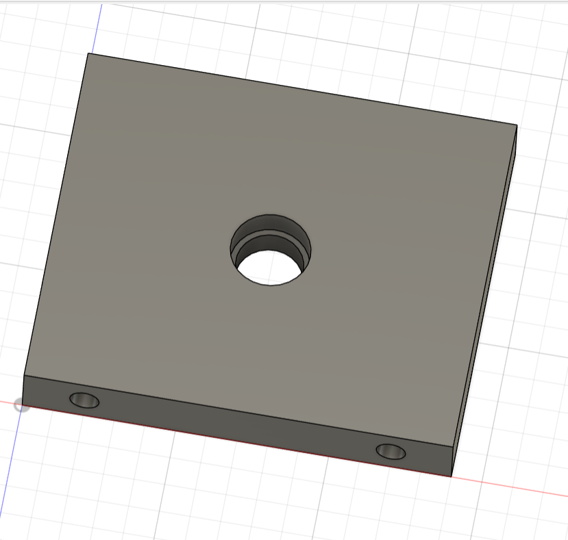
The two parts of the final project shown here are only small components. At the same time, I tried to construct the robot in Fusion 360 for the first time.
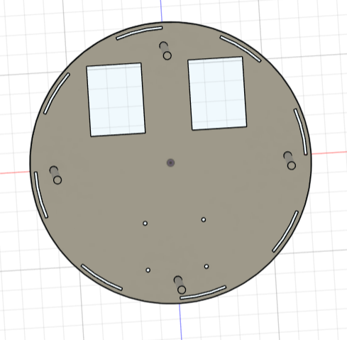
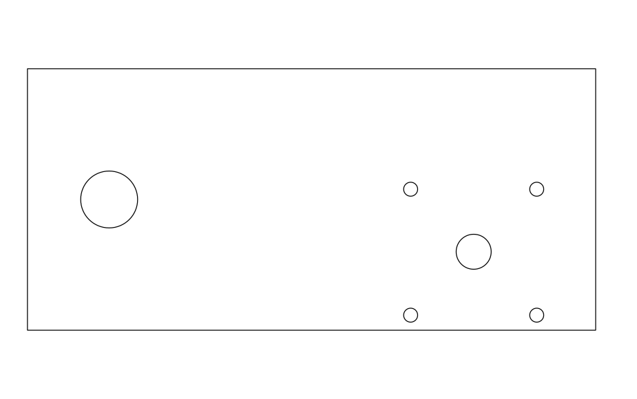
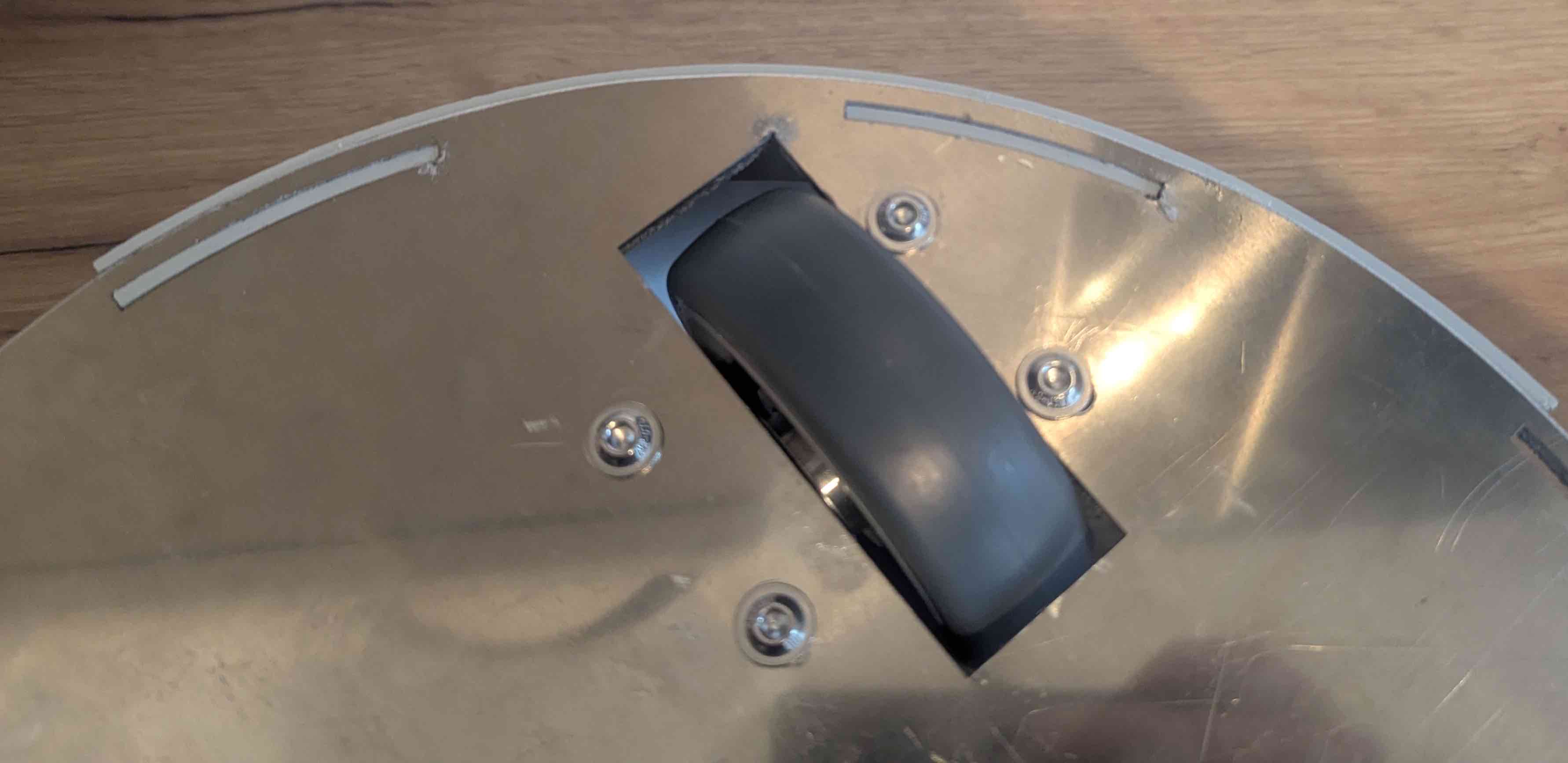
I started with the construction of the base plate, in which I made two cut-outs for the wheels and four screw holes for attaching a 360-degree rotating wheel. I positioned 8 slots on the edge into which the 3D printed cover will later be inserted. I also added 4 threaded rods to connect the two plates together.
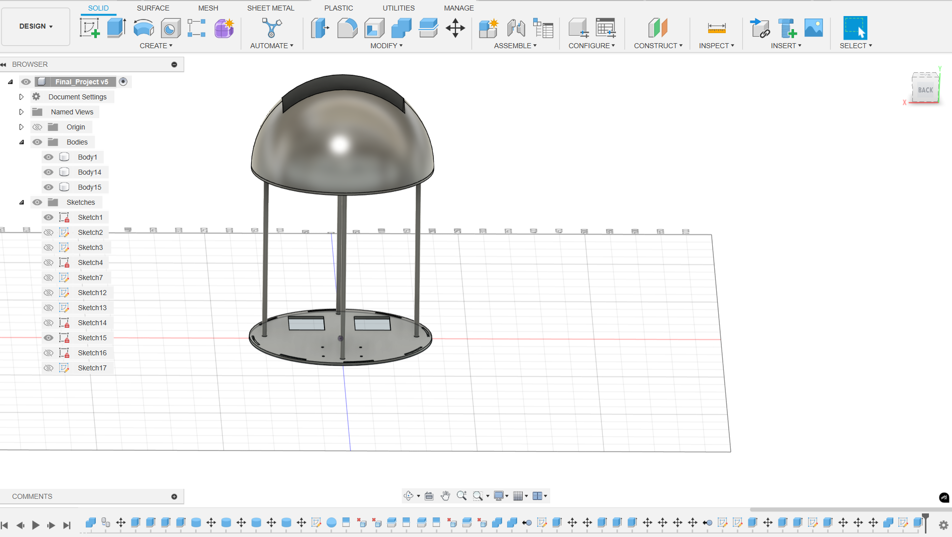
A second plate with the same slots and holes for the threaded rods was then placed on the threaded rods. The dome was then mounted on top of this and a compartment inserted.
Distance Measuring with ESP32
I chose the ESP32 for my project because of its built-in connectivity features and its simplicity to program. In addition it has many pins for connecting different sensors and devices and supports multiple energy-saving power modes.
Since I will need two ultrasonic sensors in my final project for obstacle avoidance I simulated the usage in week 4 Week 4 (Embedded Programming) of the Fab Academy.
Obstacle Avoidance – First Prototype
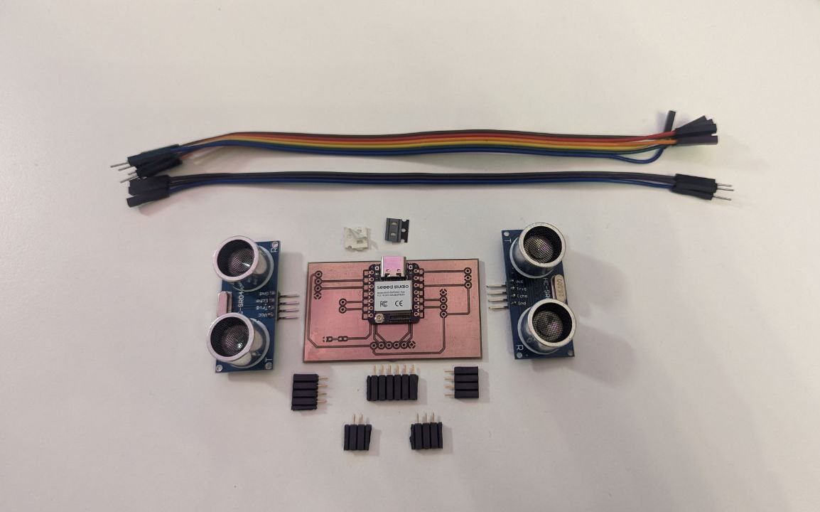
As part of my final project I need a way to detect obstacles and maintain a safe distance to users or surroundings. For that purpose, I plan to integrate two HC-SR04 ultrasonic distance sensors into the robot system.
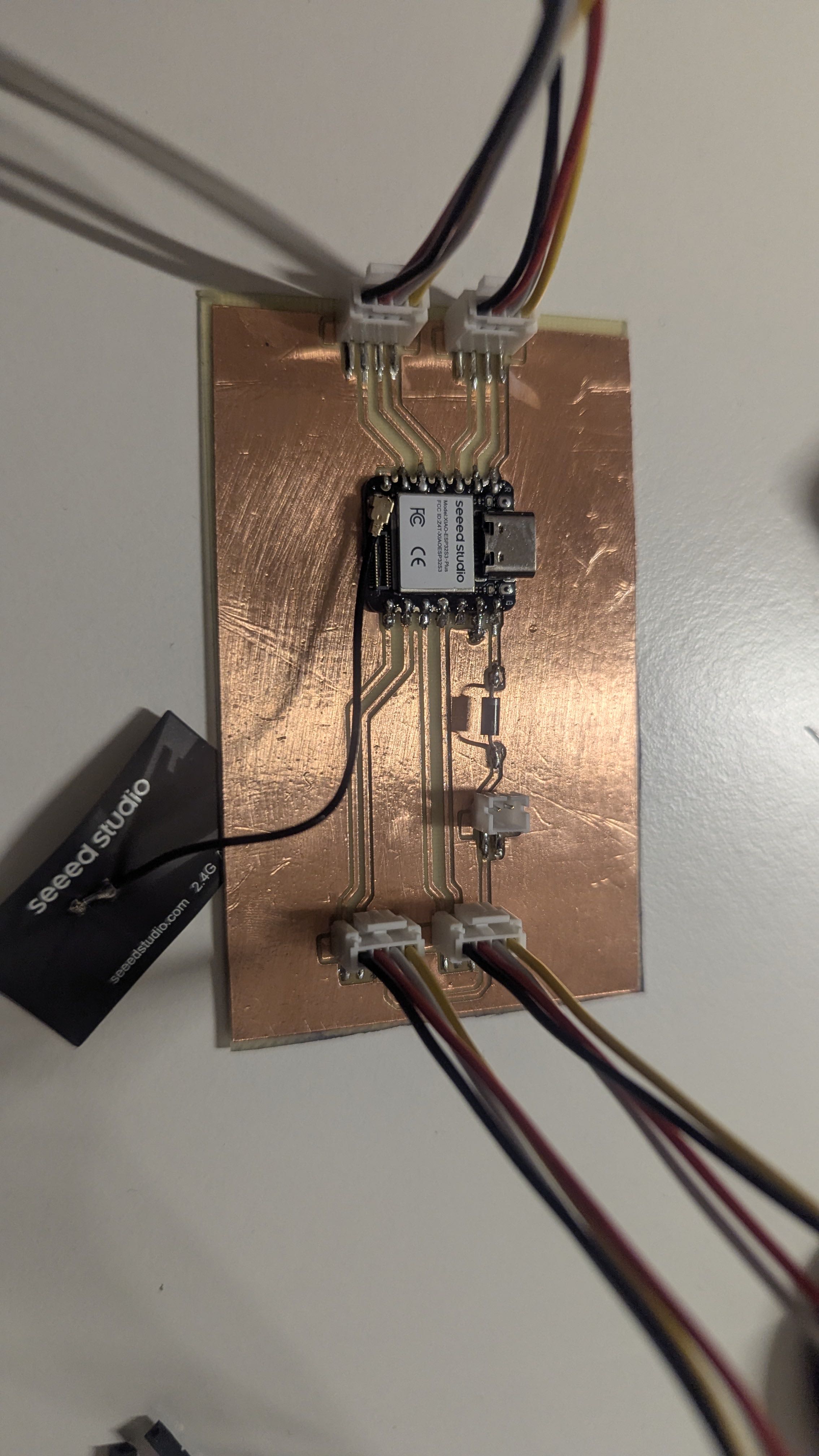
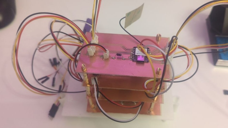
During Week 9 (Input Devices), I designed and milled a custom PCB that acts as a prototype for the sensor interface of my robot. The board is based on the Seeed Studio XIAO ESP32S3 and includes two dedicated pin headers for connecting ultrasonic sensors (VCC, TRIG, ECHO, GND), as well as a separate I2C header for communication with the main control board.
While testing the setup, I realized that the sensors require a 5V supply, which was not ideal for my 3.3V-optimized board. Fortunately, I had added a 5V fallback header. This important insight will influence the next revision of the sensor board for the final robot, where I will route 5V power directly to the sensor headers and finalize the communication interface between boards.
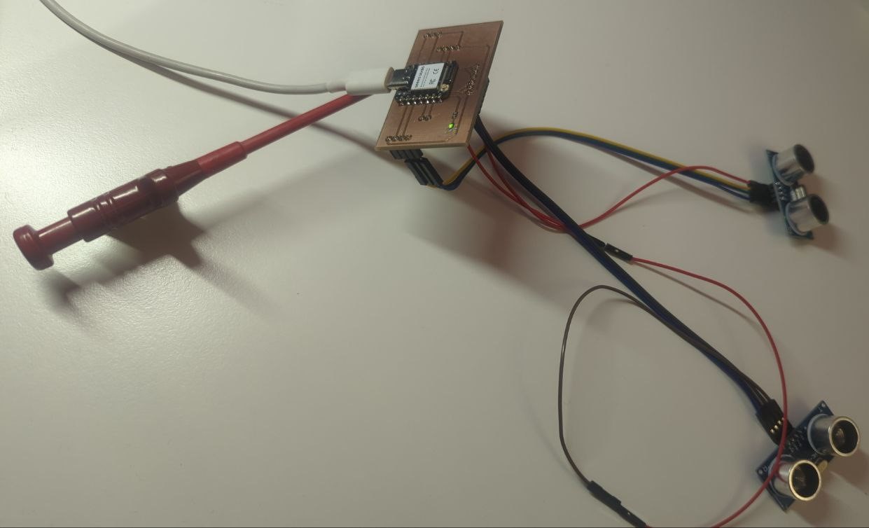
Building and testing this prototype in Week 9 was a really important step for my robot project – it helped me figure out how to connect the sensors properly, get reliable measurements, and prepare everything for future I2C communication between the boards.
Manufacturing Components
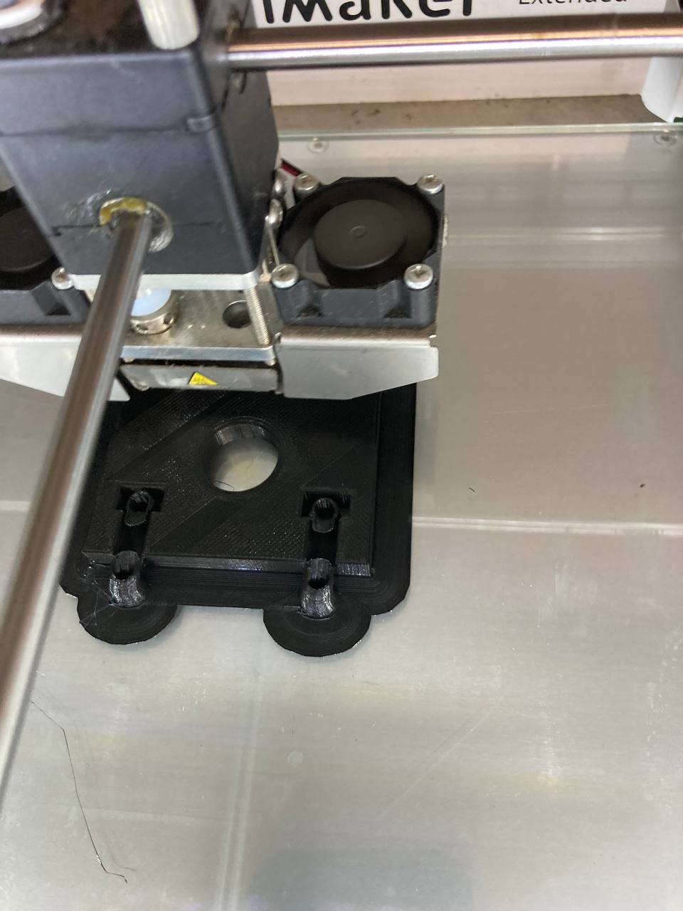
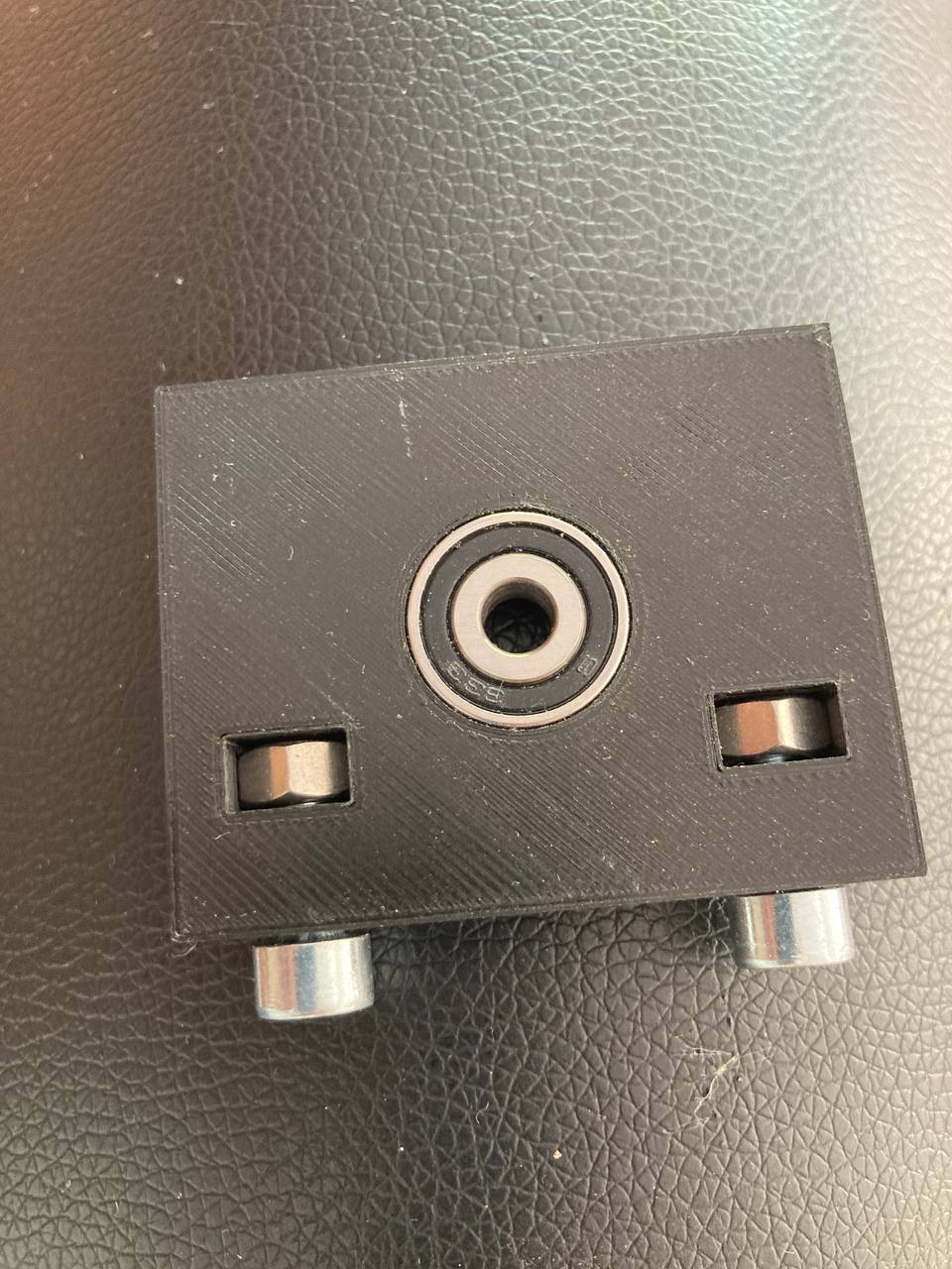
Bearing Blocks
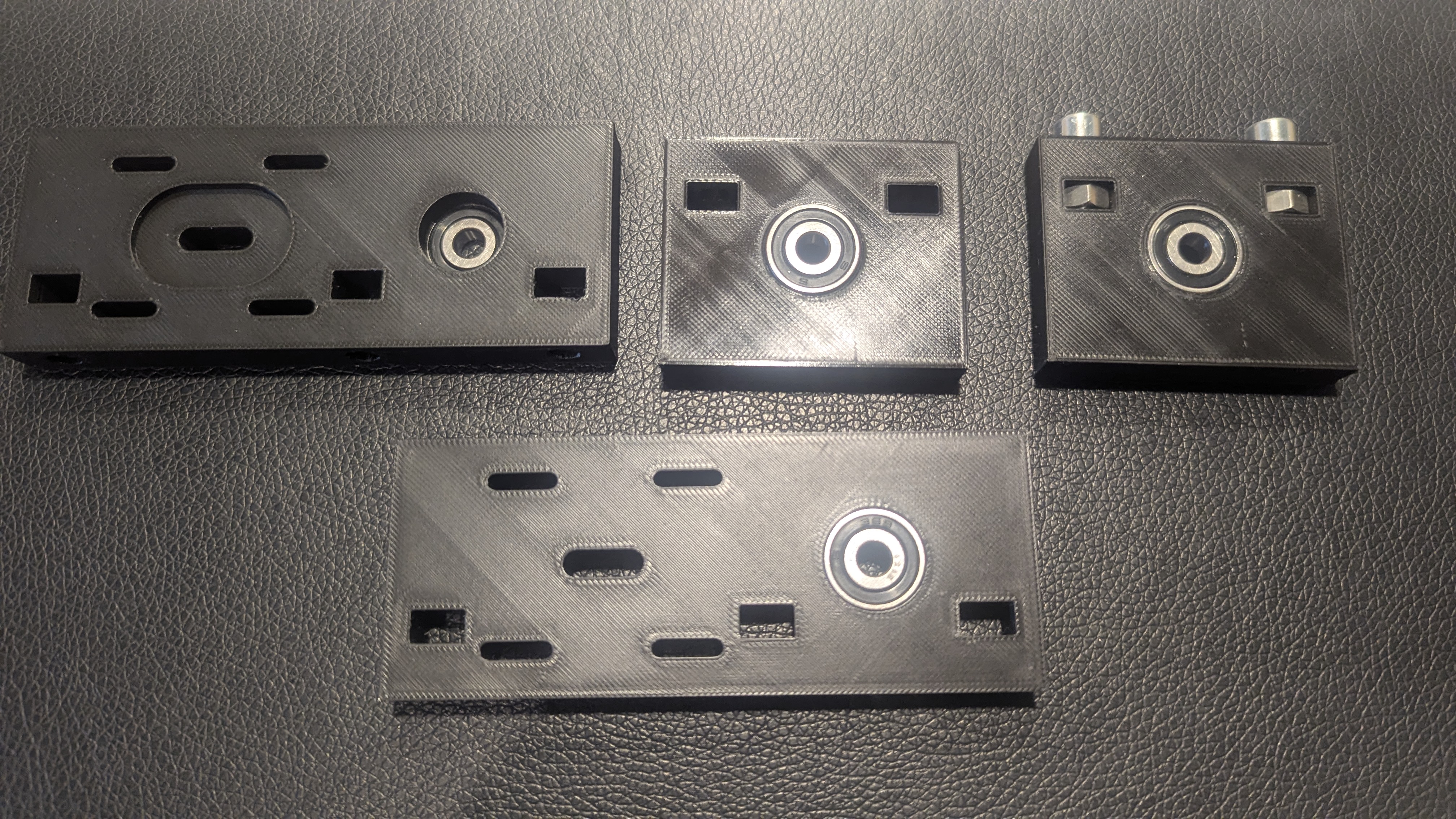
I took the NEMA 17 dimensions from the manual. The bearing blocks were modeled in Fusion 360 and 3D printed in PLA. After printing, the ball bearings were pressed into the corresponding recesses. To allow the bearing blocks to be firmly screwed to the base plate, dedicated recesses for nuts were incorporated into the design, into which the nuts were inserted before assembly.
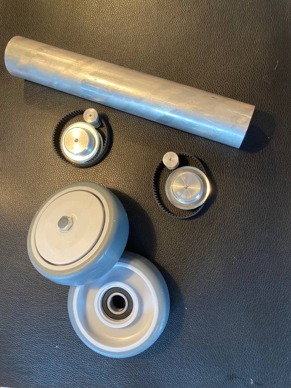
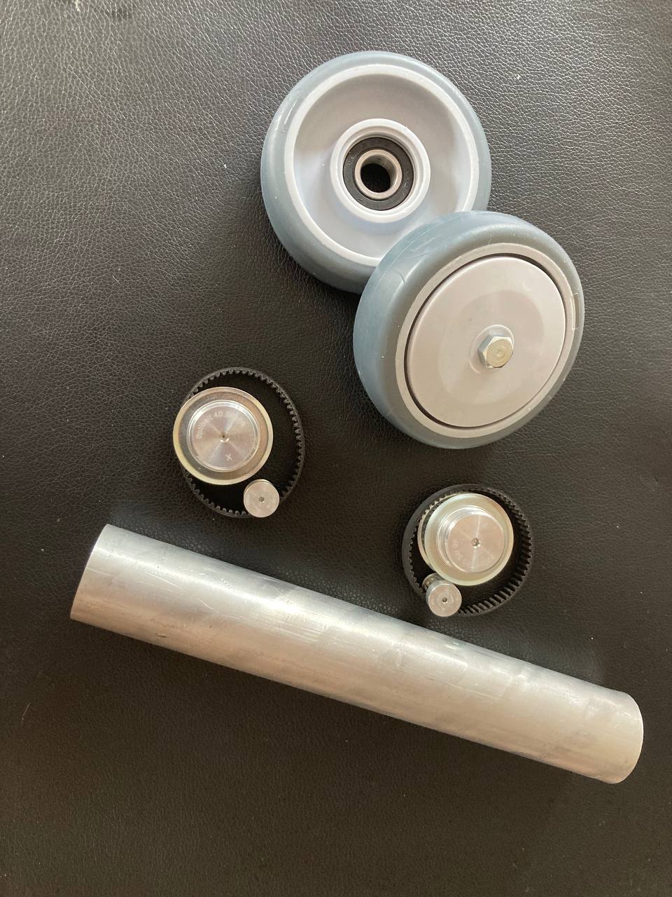
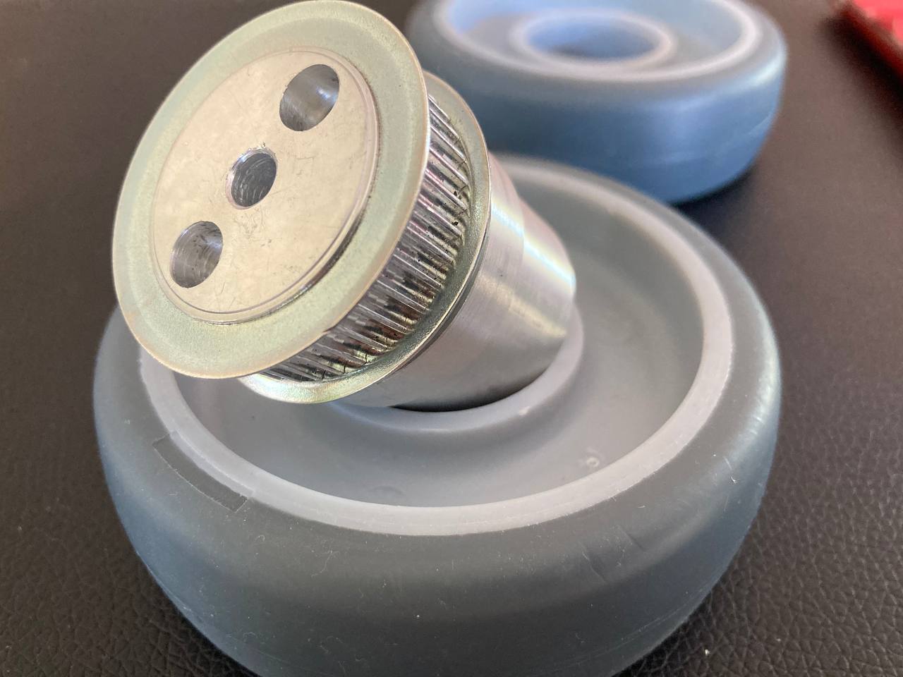
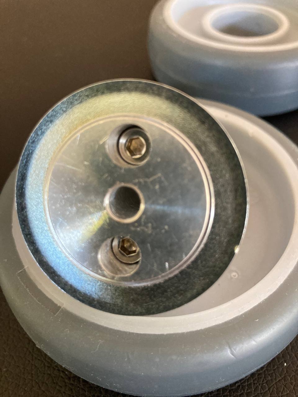
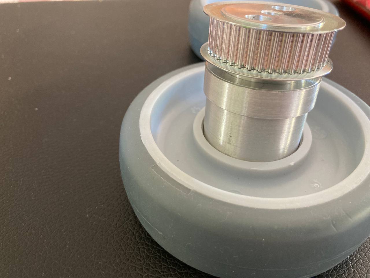
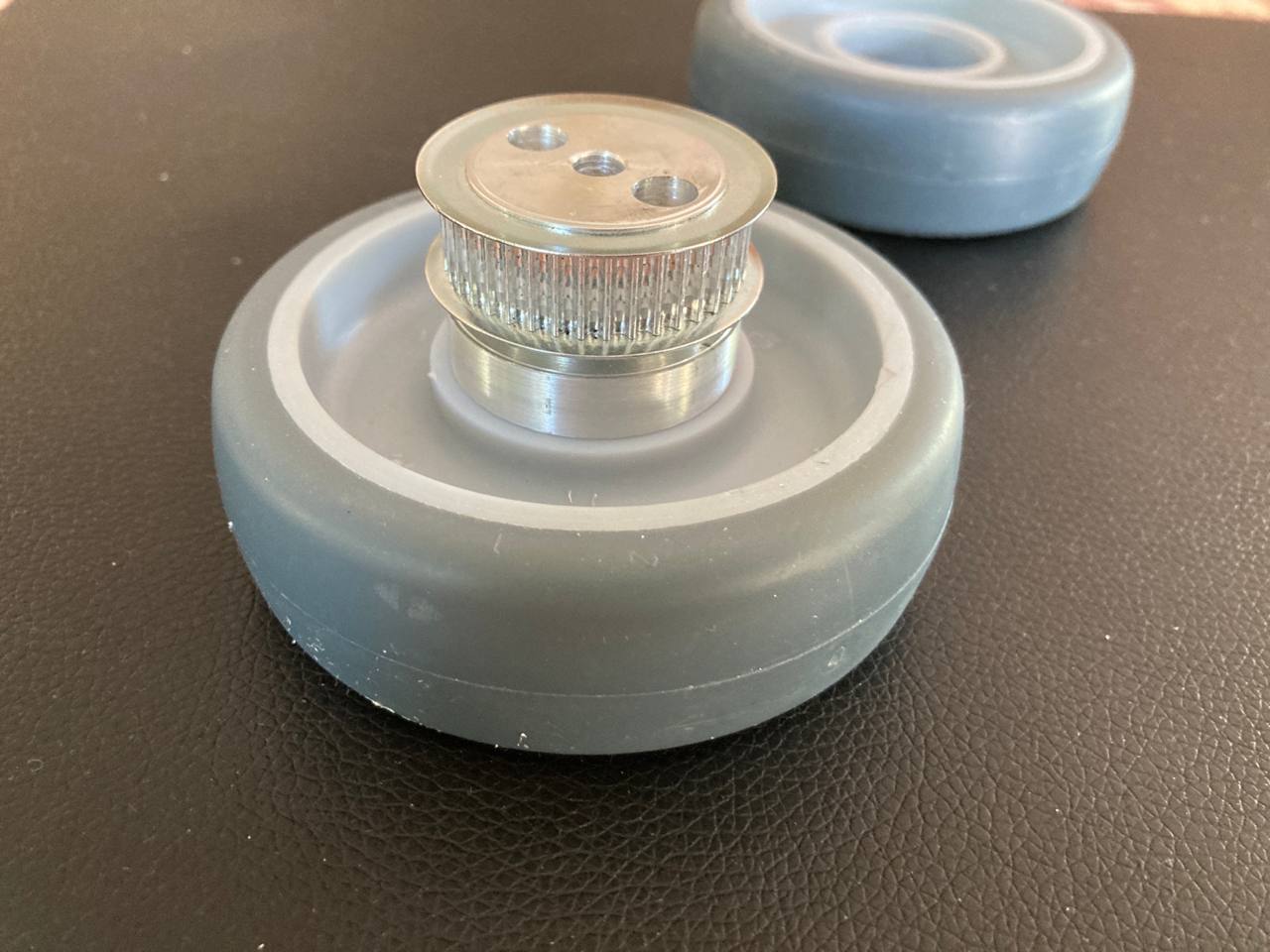
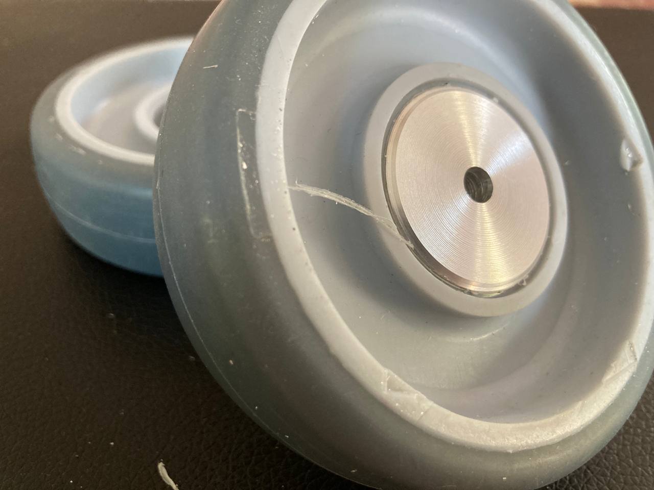
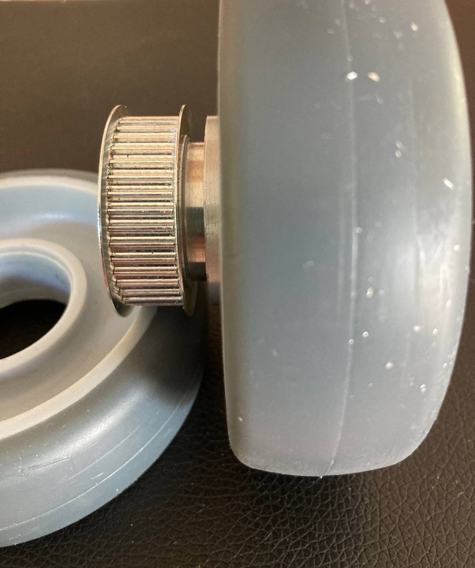
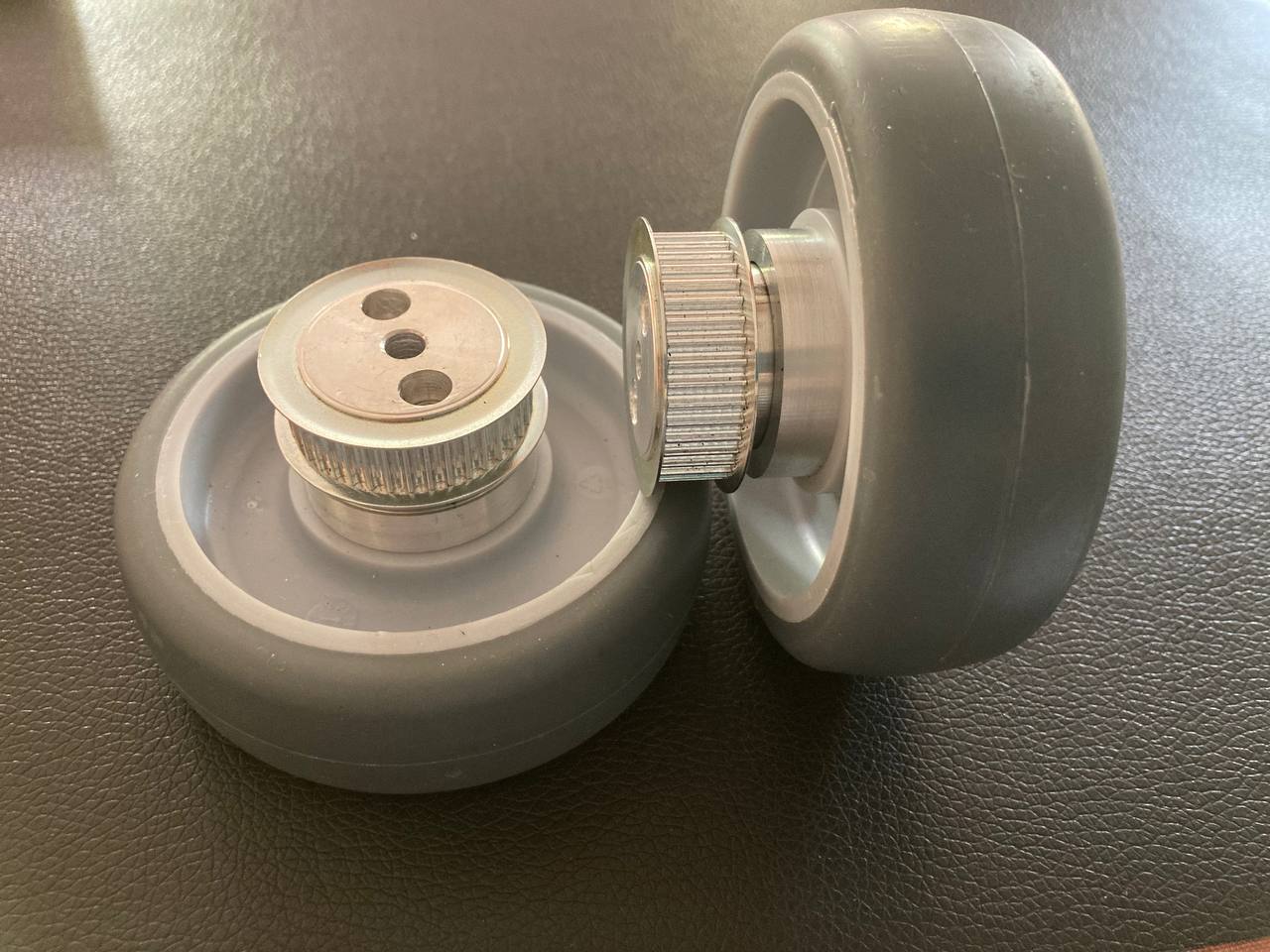
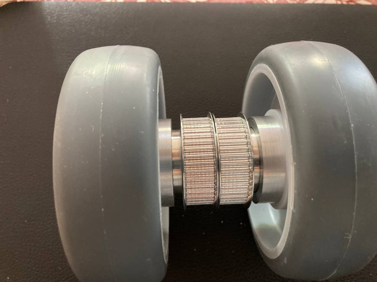
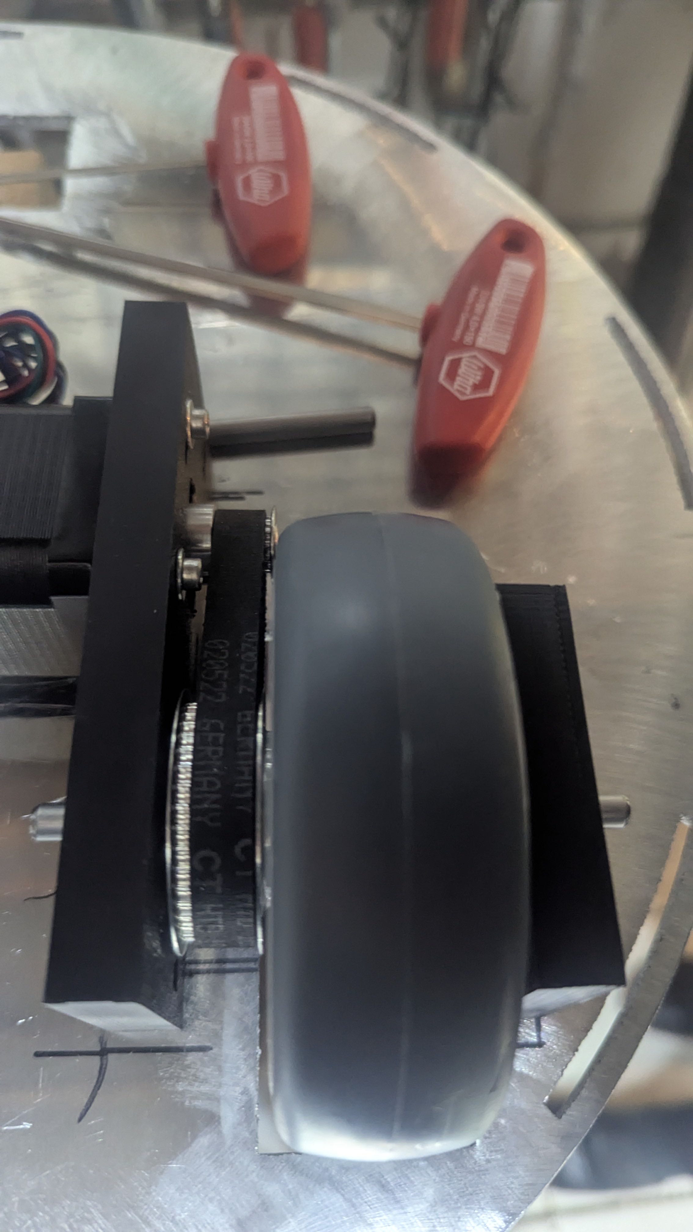
Wheels
The original axle inserts were removed from the wheels. Custom aluminum hubs were then manufactured on a lathe, onto which the timing belt pulleys were mounted. The completed hub and pulley assembly was then pressed into the wheel, creating a solid and precisely fitting drive unit.
Chassis
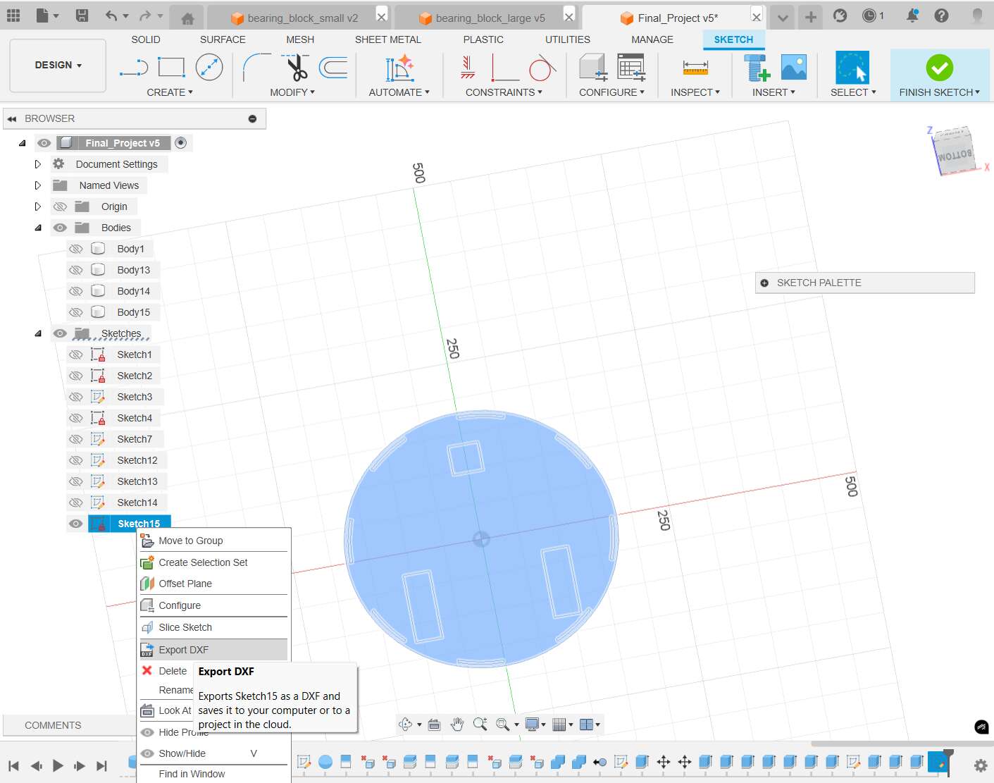
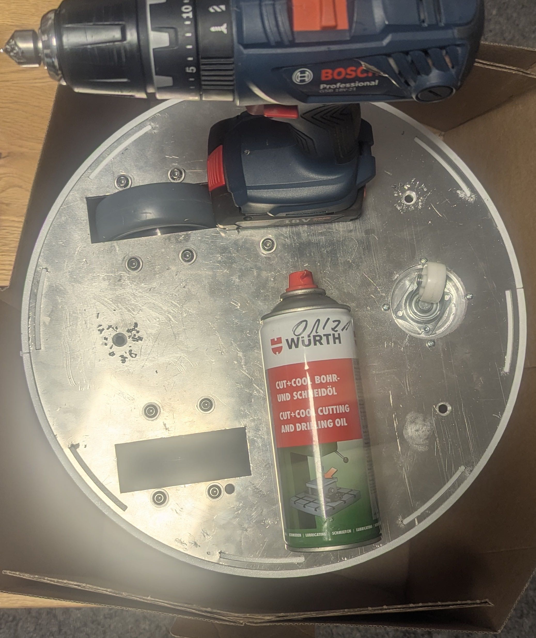
You can find a detailed description of the manufacturing process of my bottom and top plate on Assignment 16
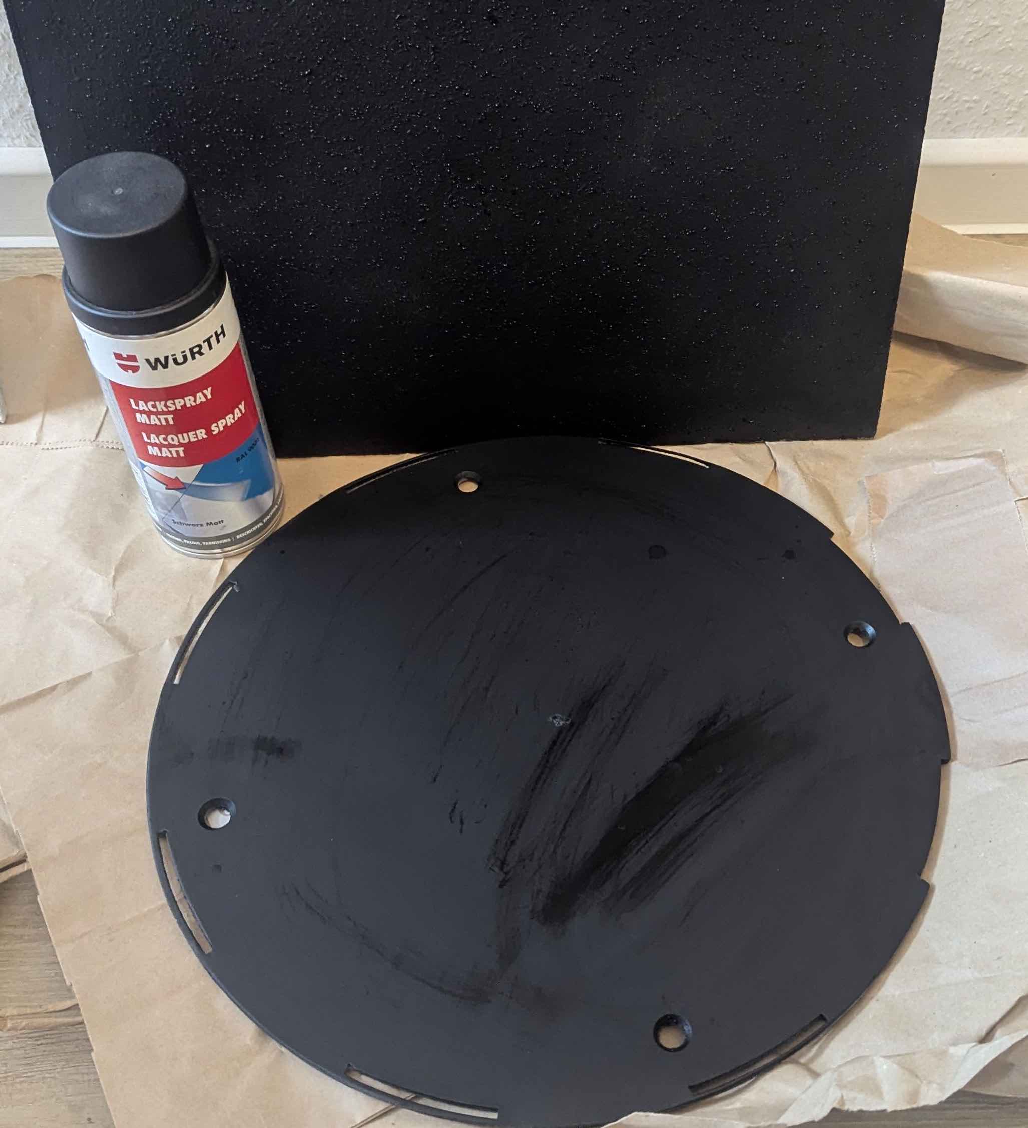
As you can see on the following pictures some postprocessing was necessary.
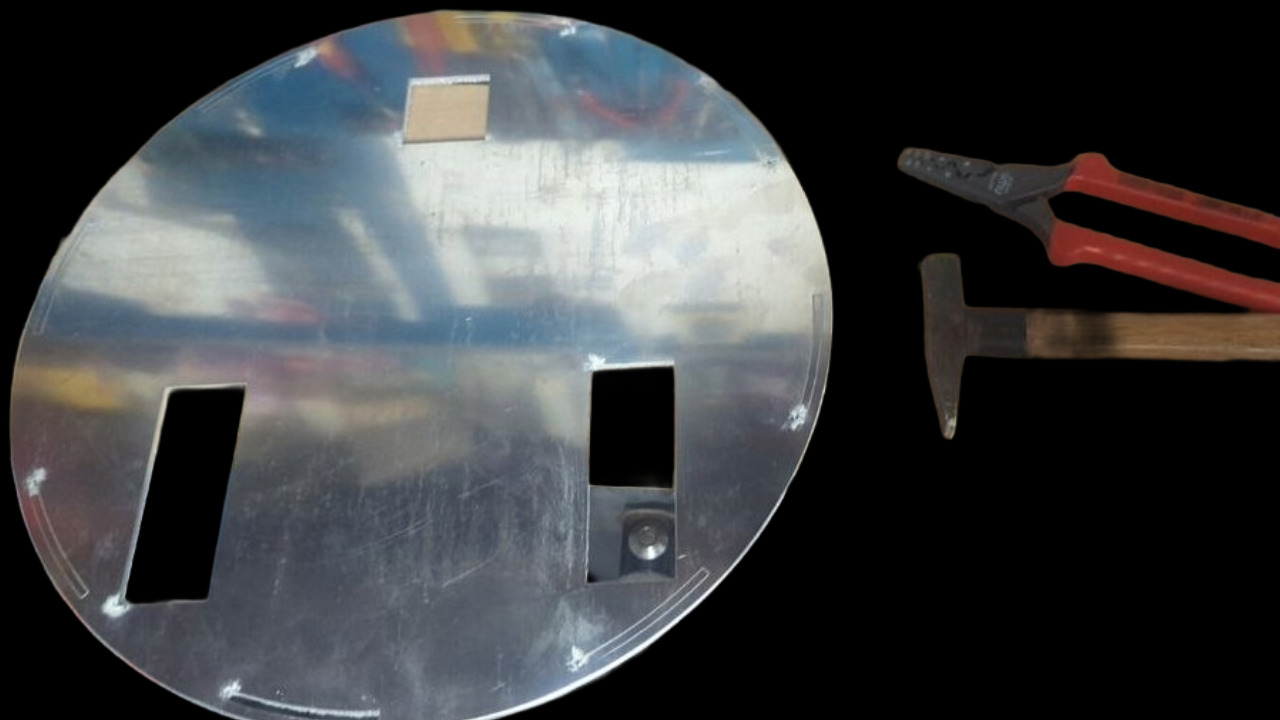
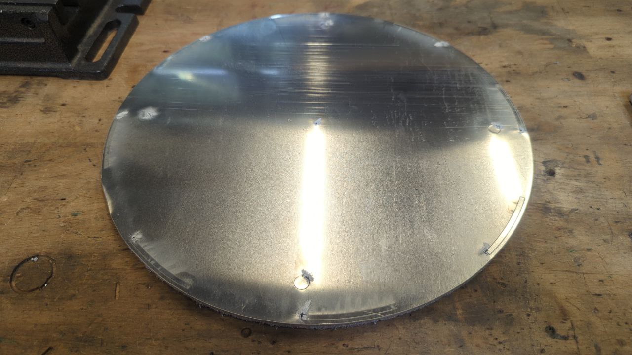
To ensure a better look of the robot I painted the top plate black.
Enclosure
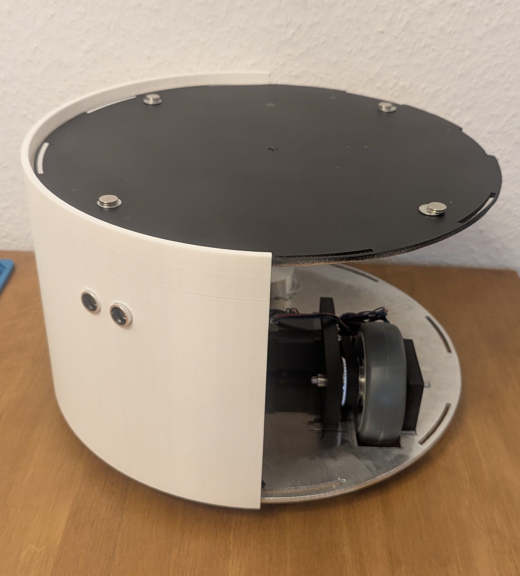
The enclosure was designed in Fusion 360 as a relatively simple model. The key design features are the ring-shaped snap-in segments on the top and bottom edges, which slot into corresponding cutouts in the metal top and bottom plates to hold everything together without additional fasteners, as well as dedicated cutouts for the two HC-SR04 ultrasonic sensors. The enclosure was printed in PLA.
The videos below show the print process and how the enclosure segments connect with the top and bottom plates in Fusion 360:
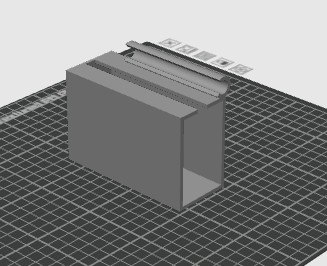
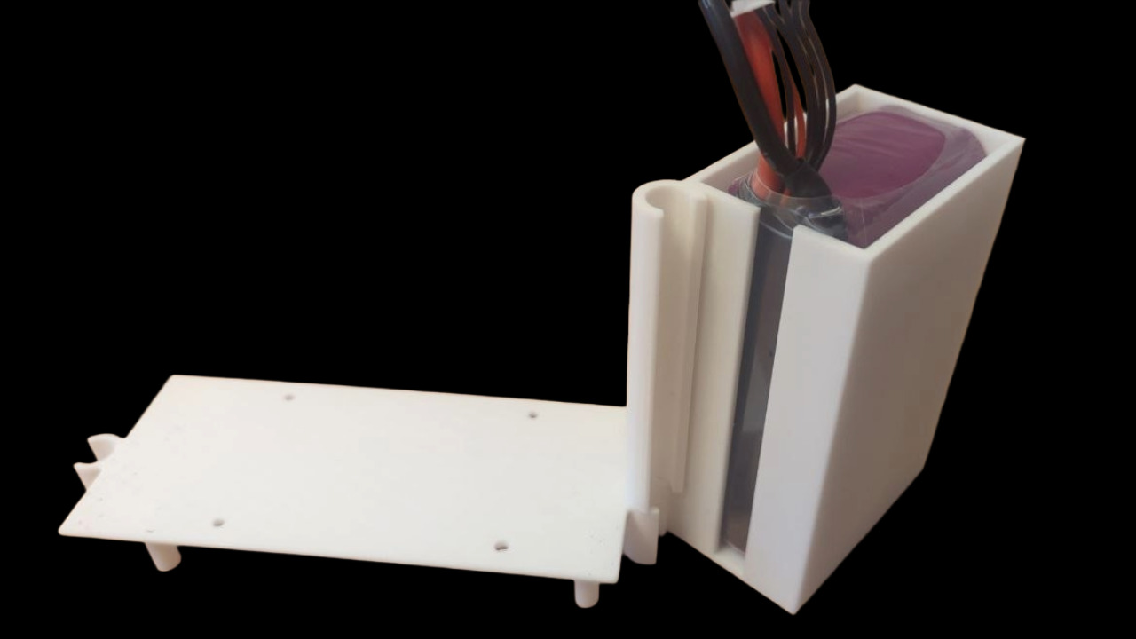
Battery Holder
To keep the battery securely in place, I designed and printed a dedicated battery holder that attaches to one of the inner rods at the same fixing point as the PCB tower. A detailed description can be found on the System Integration page.
Basket
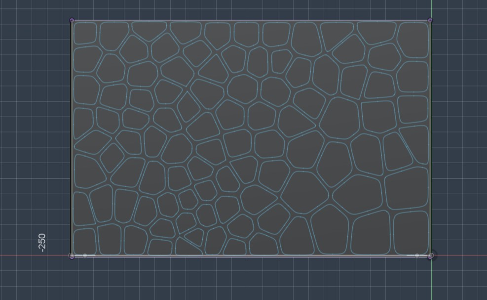
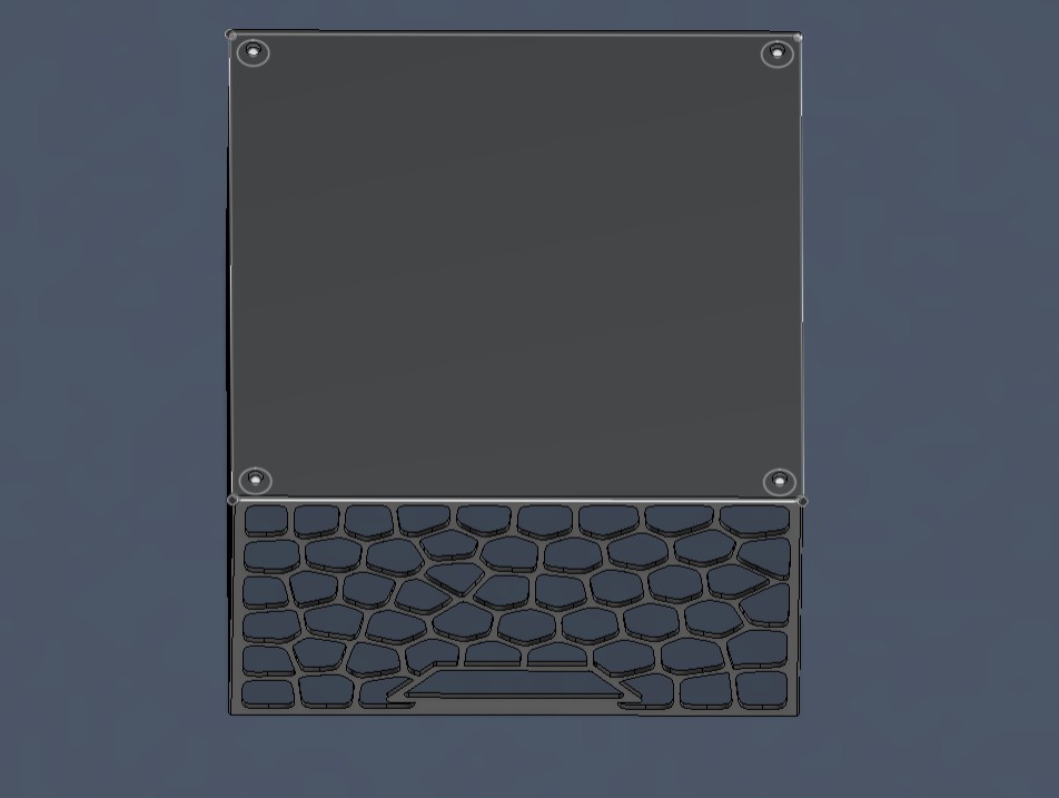
I made a cardboard template to determine the exact size of the basket and decide where to place the magnets.
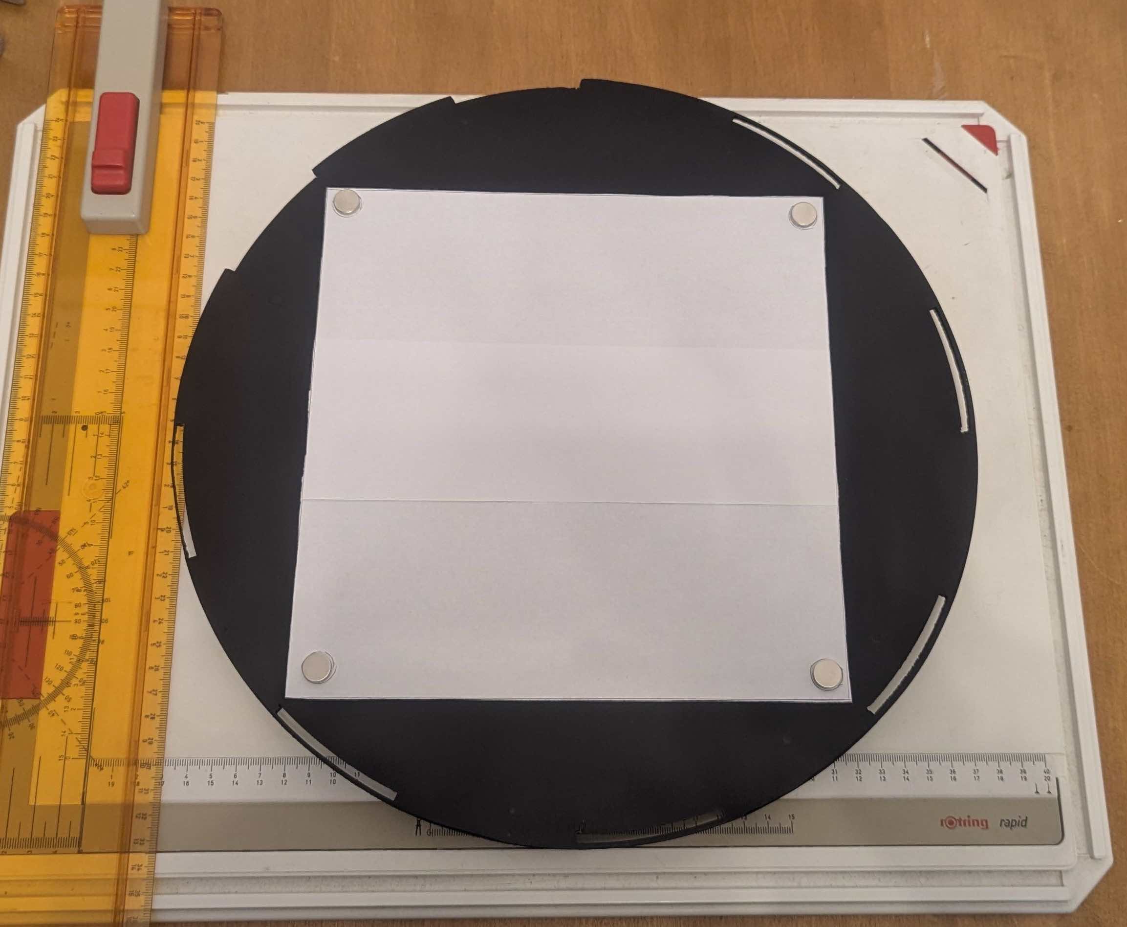
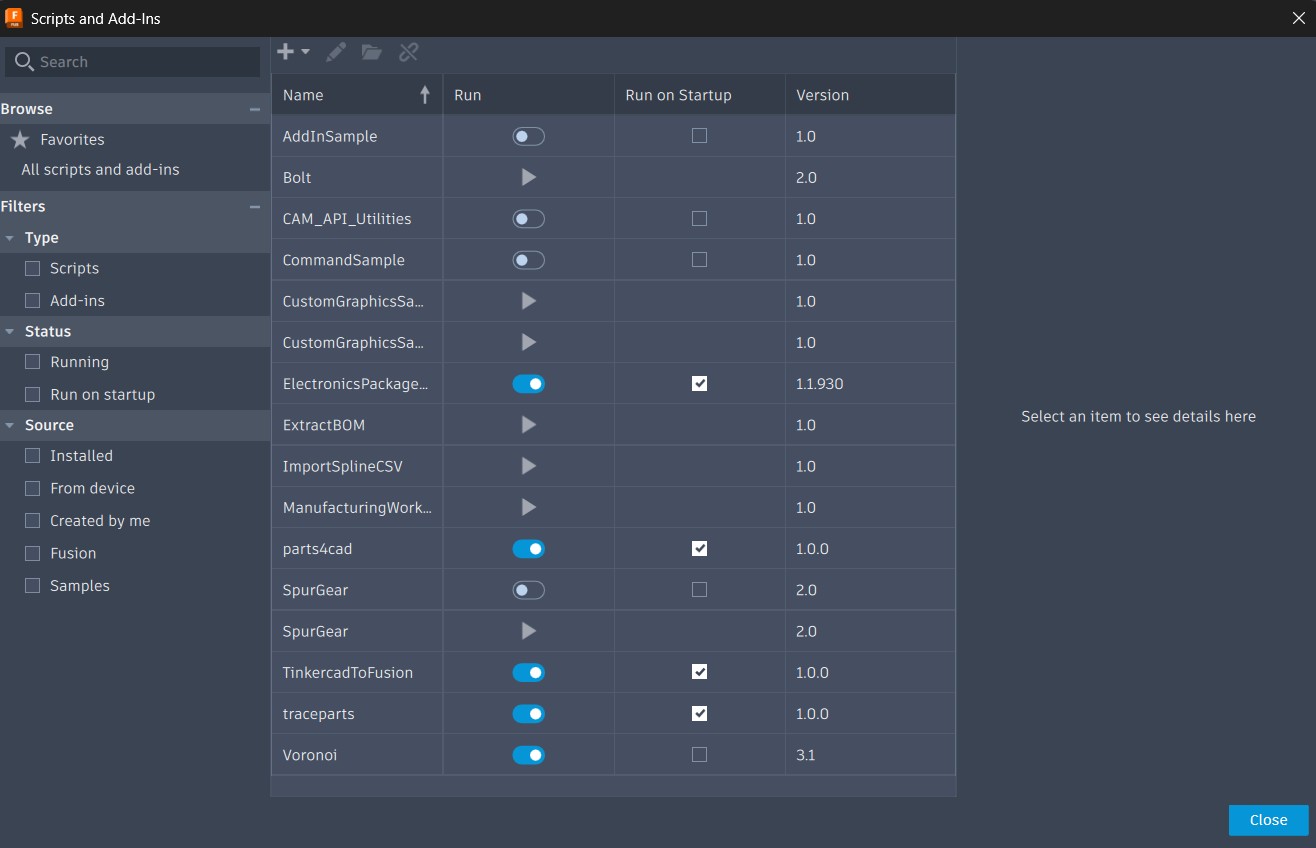
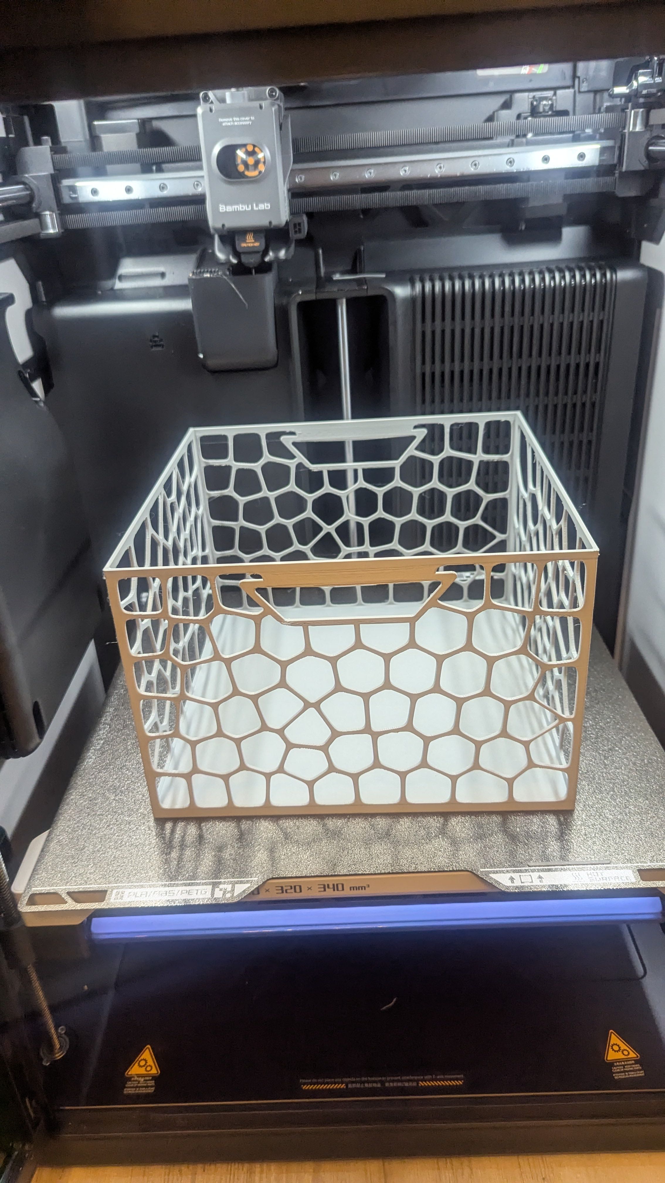
After that I designed the basket in Fusion 360 and printed it. The distinctive Voronoi surface pattern was created using a manually installed Fusion 360 plugin. The design also includes handles on two sides of the basket for easy carrying, as well as recesses for the magnets, which were pressed in after printing to create the magnetic connection to the robot.
 -
- And here's a video of the working mechanism:
PCB Design and Manufacturing
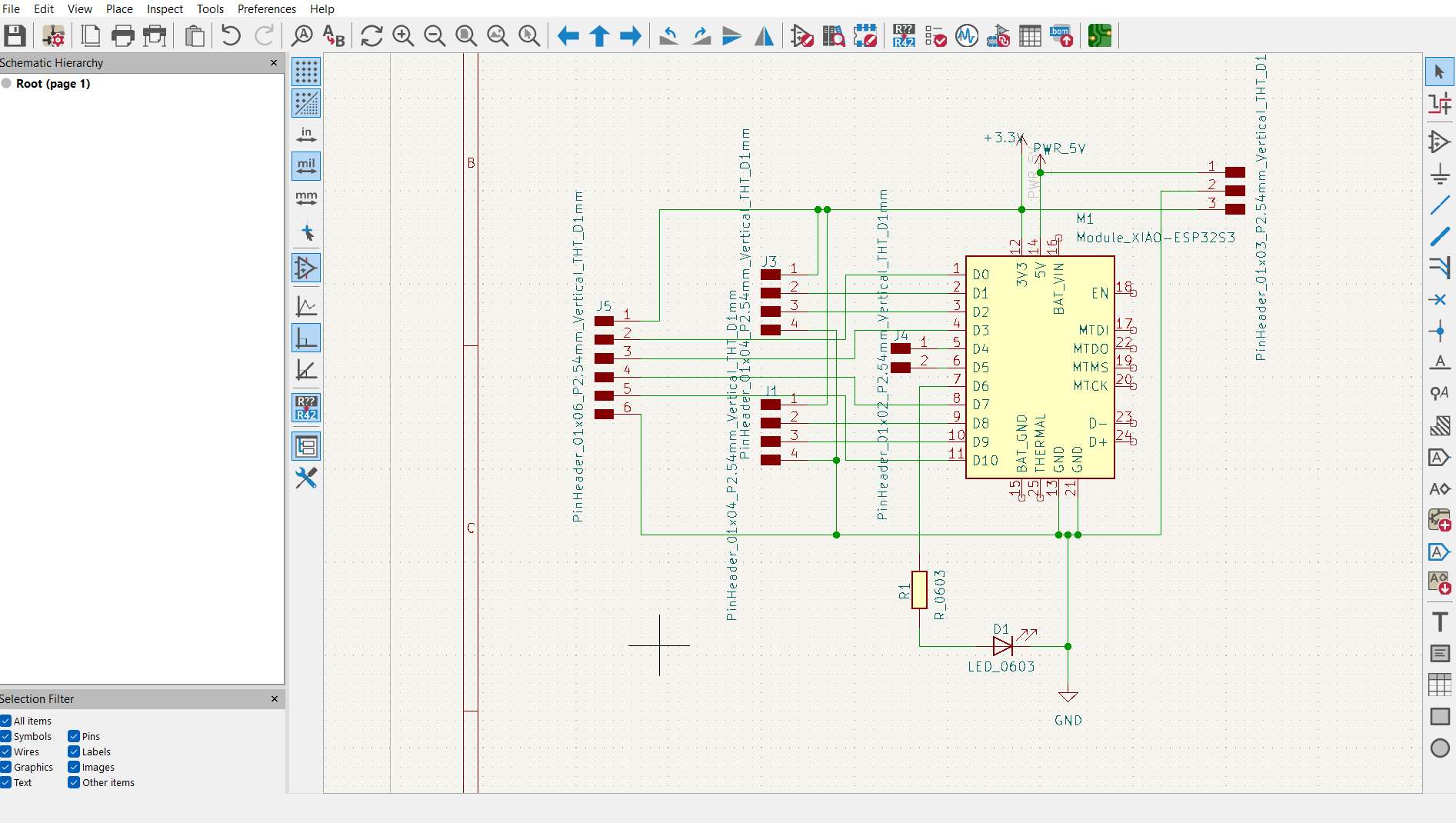
PCB Design
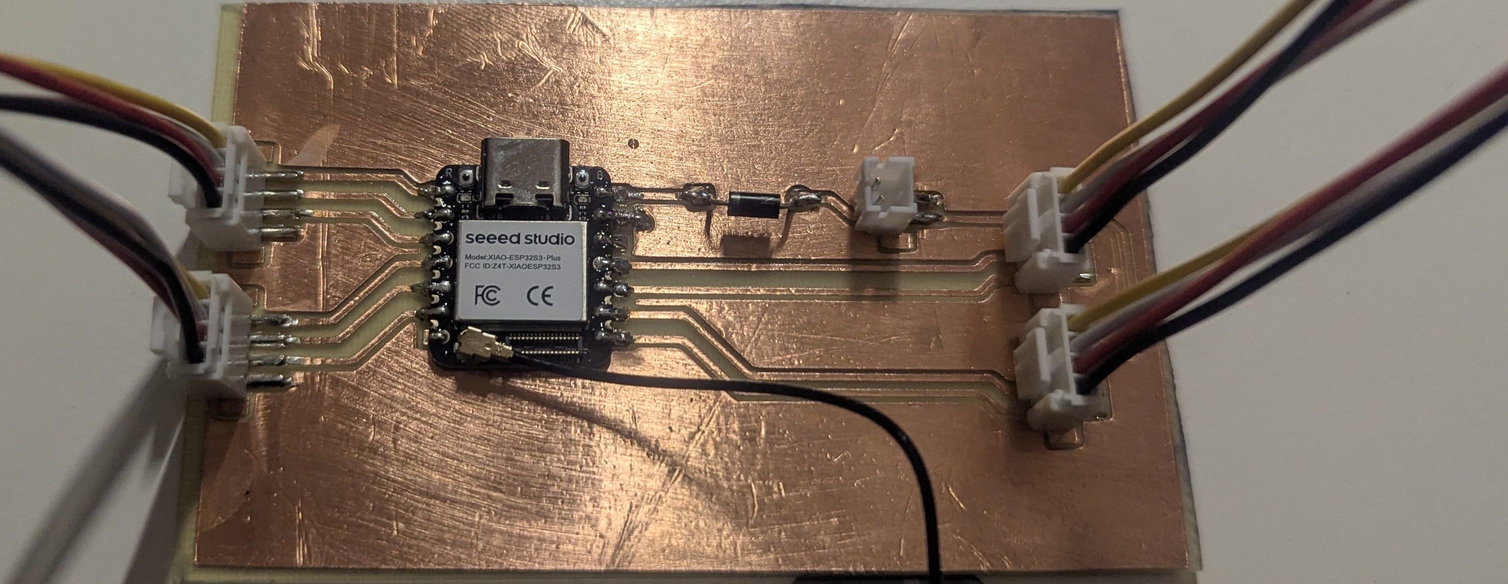
After further considerations and the drawing of the sketches, I decided to give up the idea of multiple microcontrollers communicating via I2C. The ESP32S3 or ESP32S3 Plus has a sufficient amount of IO Pins and computing power to handle the connection between the ESP32 and the React Native App via an access point, to read sensor data and to send controls to the motor driver.
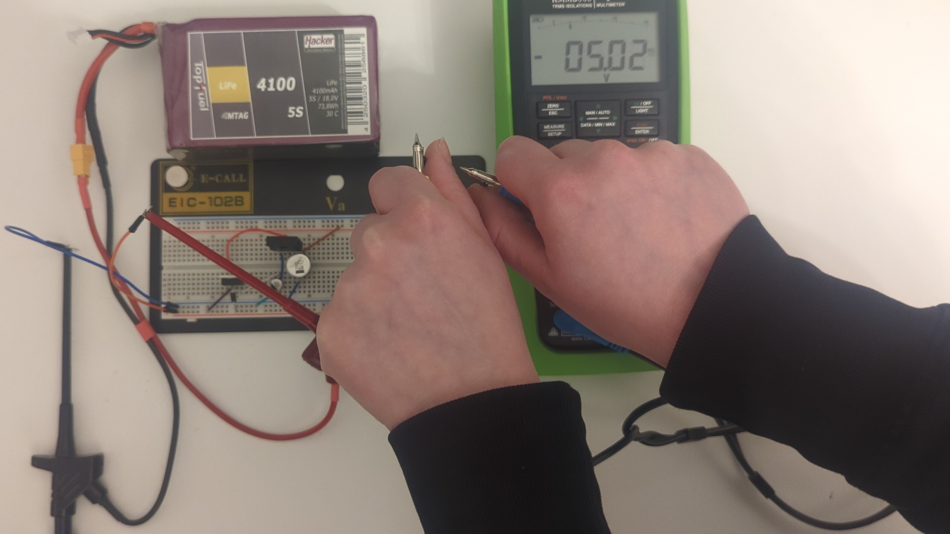
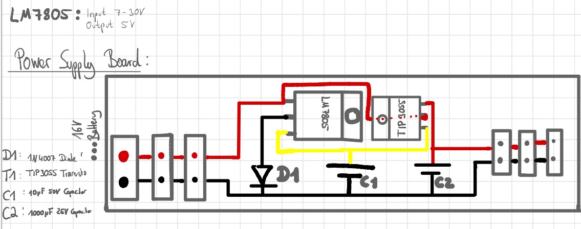
Voltage Regulation and Power Supply
The robot is powered by a 16V LiFe battery. Since the HC-SR04 ultrasonic sensors and the TMC2209 motor drivers all require 5V, a power supply board was designed to step down the battery voltage accordingly. The board is built around an LM7805 voltage regulator (input 7–30V, output 5V), supported by a TIP3055 transistor, a 1N4007 diode, and two smoothing capacitors (10µF 50V and 1000µF 25V) as recommended by the referenced YouTube tutorial.
The XIAO ESP32S3 is powered via its 5V input pin with a diode, which mirrors the behavior of USB power input. The board then regulates 5V down to 3.3V internally for the microcontroller. Since 3.3V is only used internally by the ESP32 and not distributed to any other component, no external 3.3V rail was needed. All external components, sensors and motor drivers, run directly on the 5V output of the power supply board.
For details on how the power supply board is integrated into the overall system, see the System Integration page (Week 15)
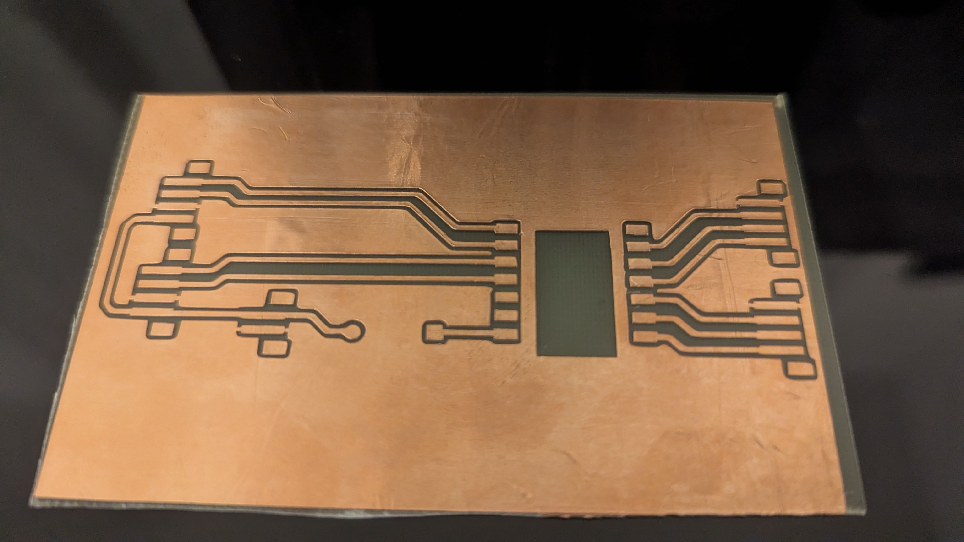
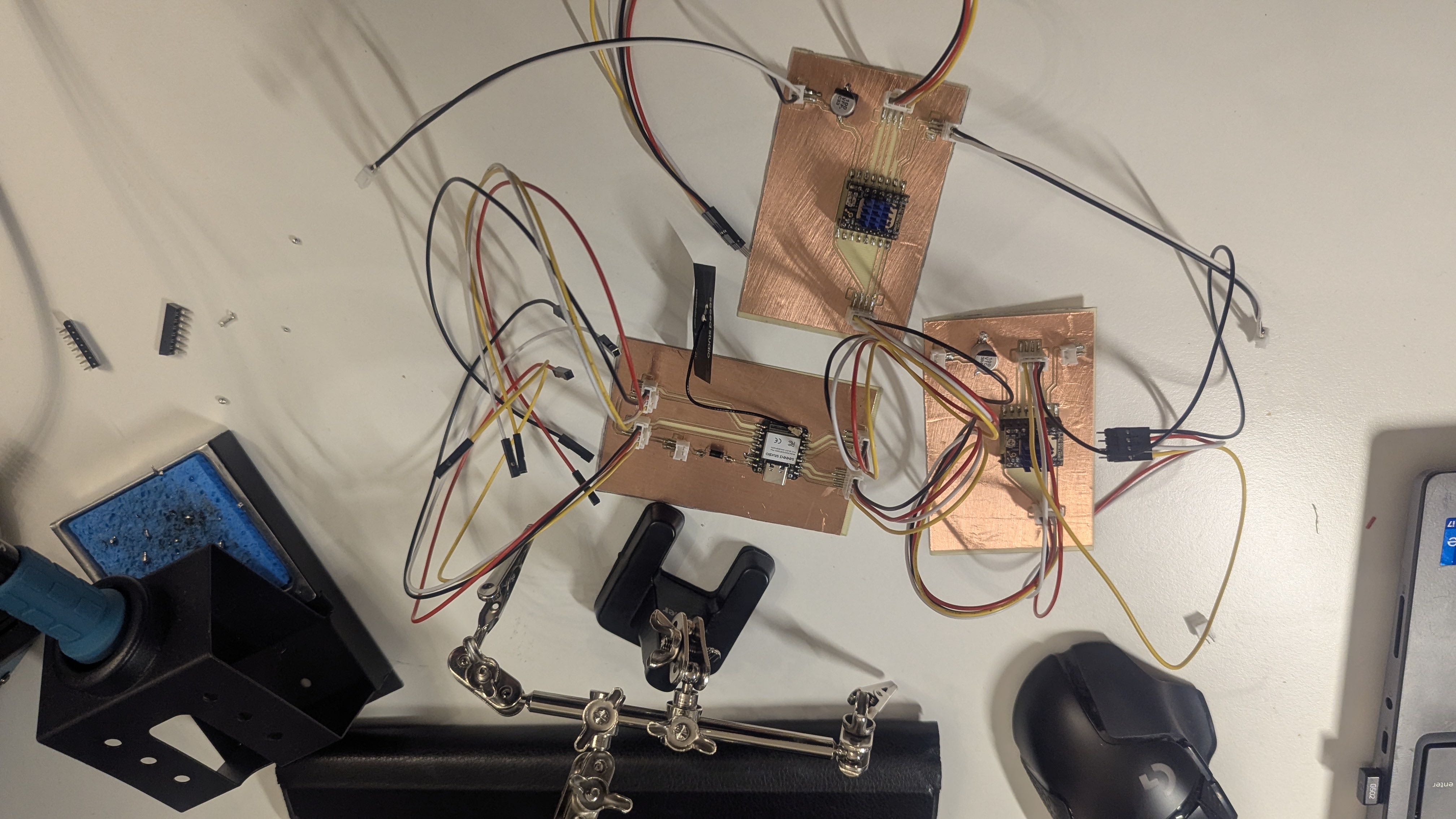
Since I wanted to do as much as possible at home and had just gotten my new BambuLab H2S with a plotter, I thought about the best way to make PCBs using copper foil and fiberglass-reinforced plastic (FR4) boards.
First, I tested various plotter settings in combination with the copper foil.
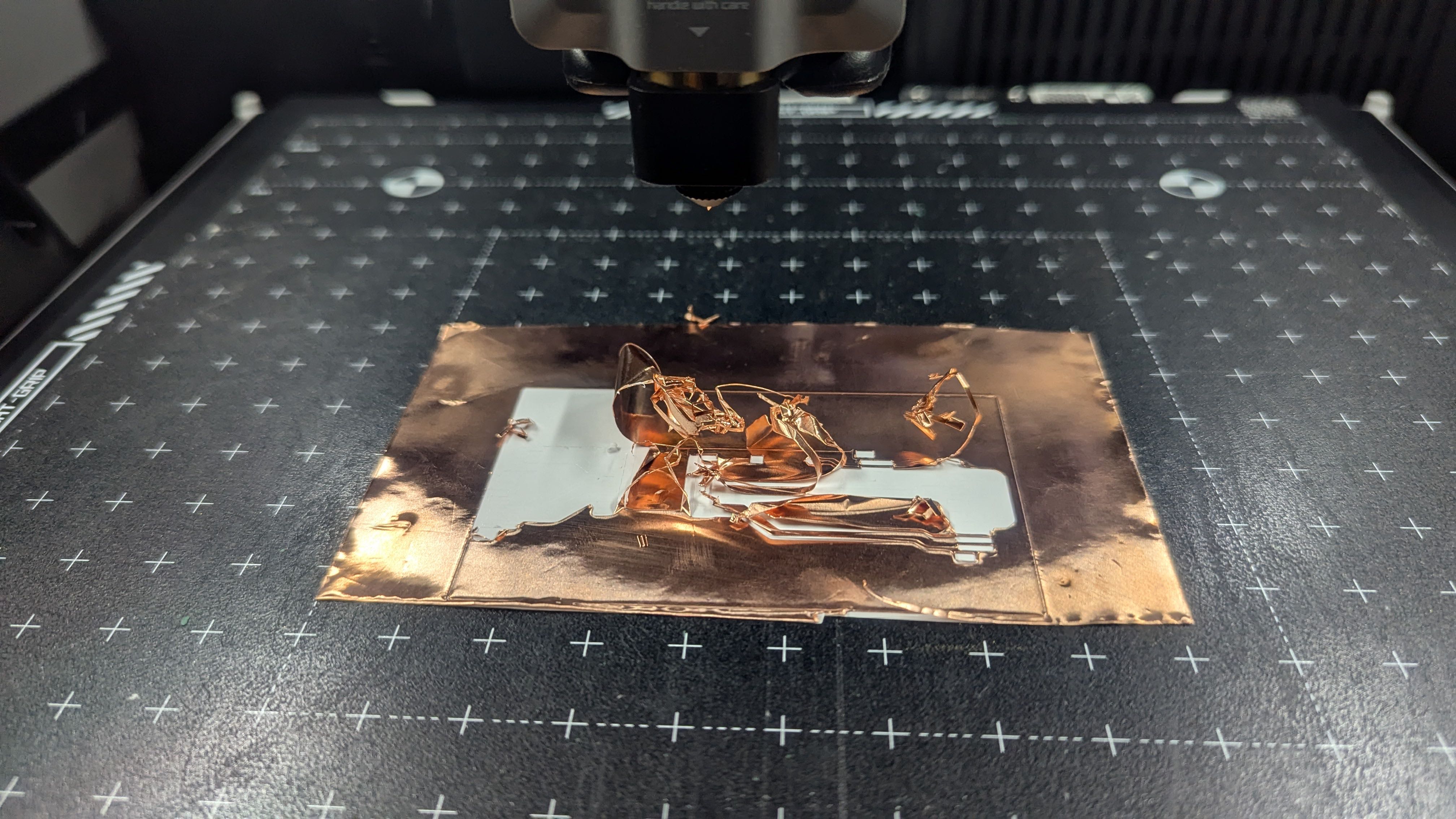
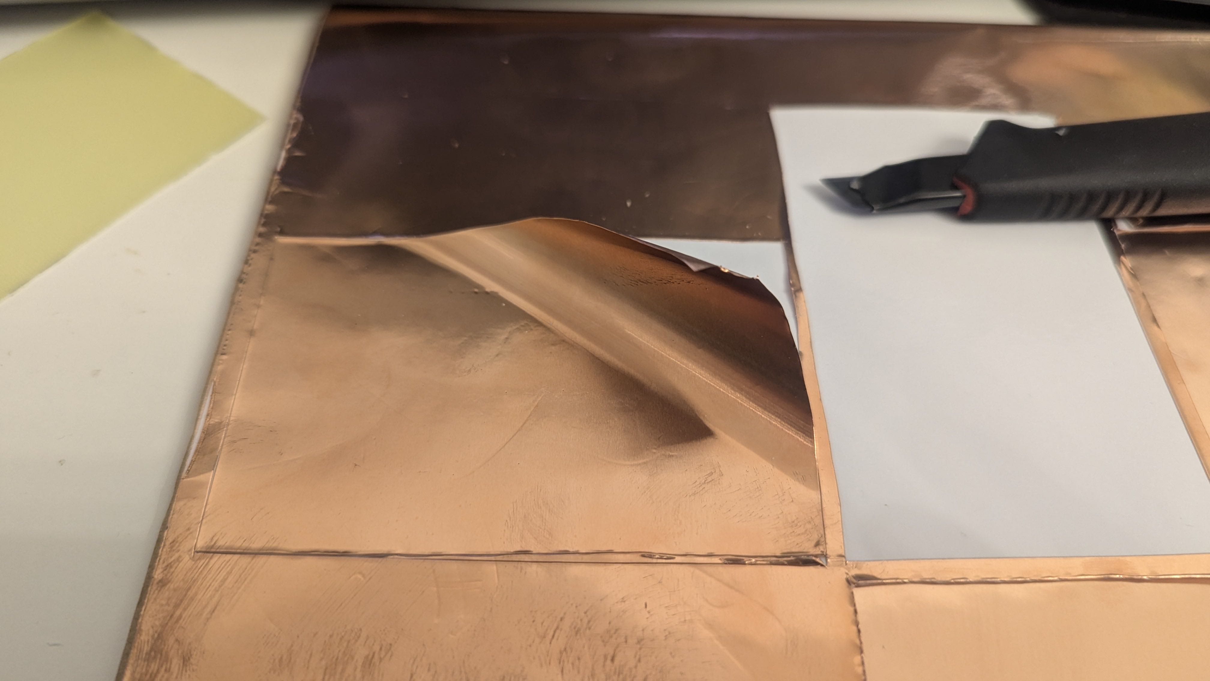
Although the settings improved, at some point the copper foil still peeled away from the slippery backing film, making it impossible to cut the material precisely.
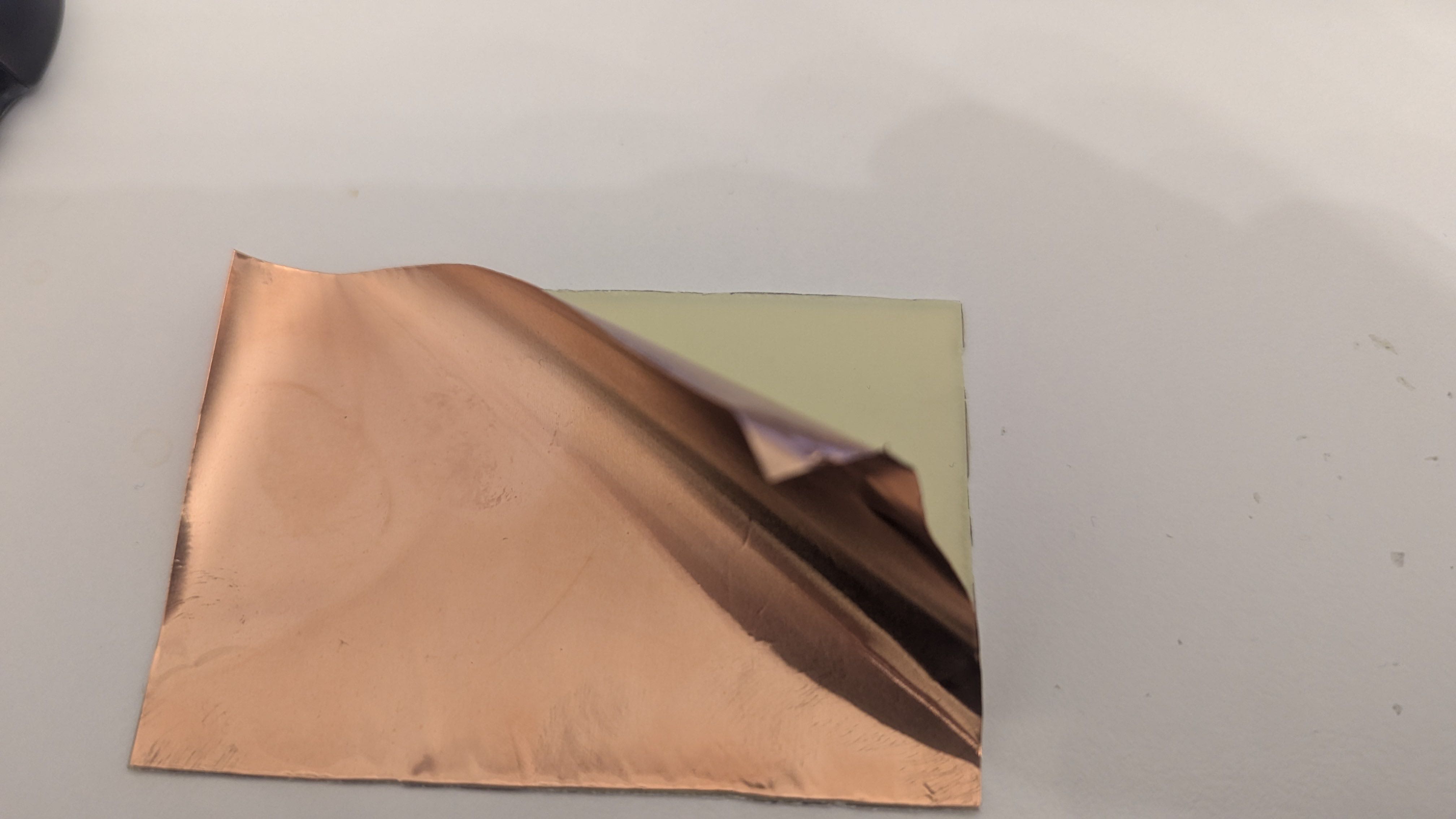
So, as a test, I stuck a piece of copper foil onto the fiberglass panel and then plotted it to see if it would work that way.
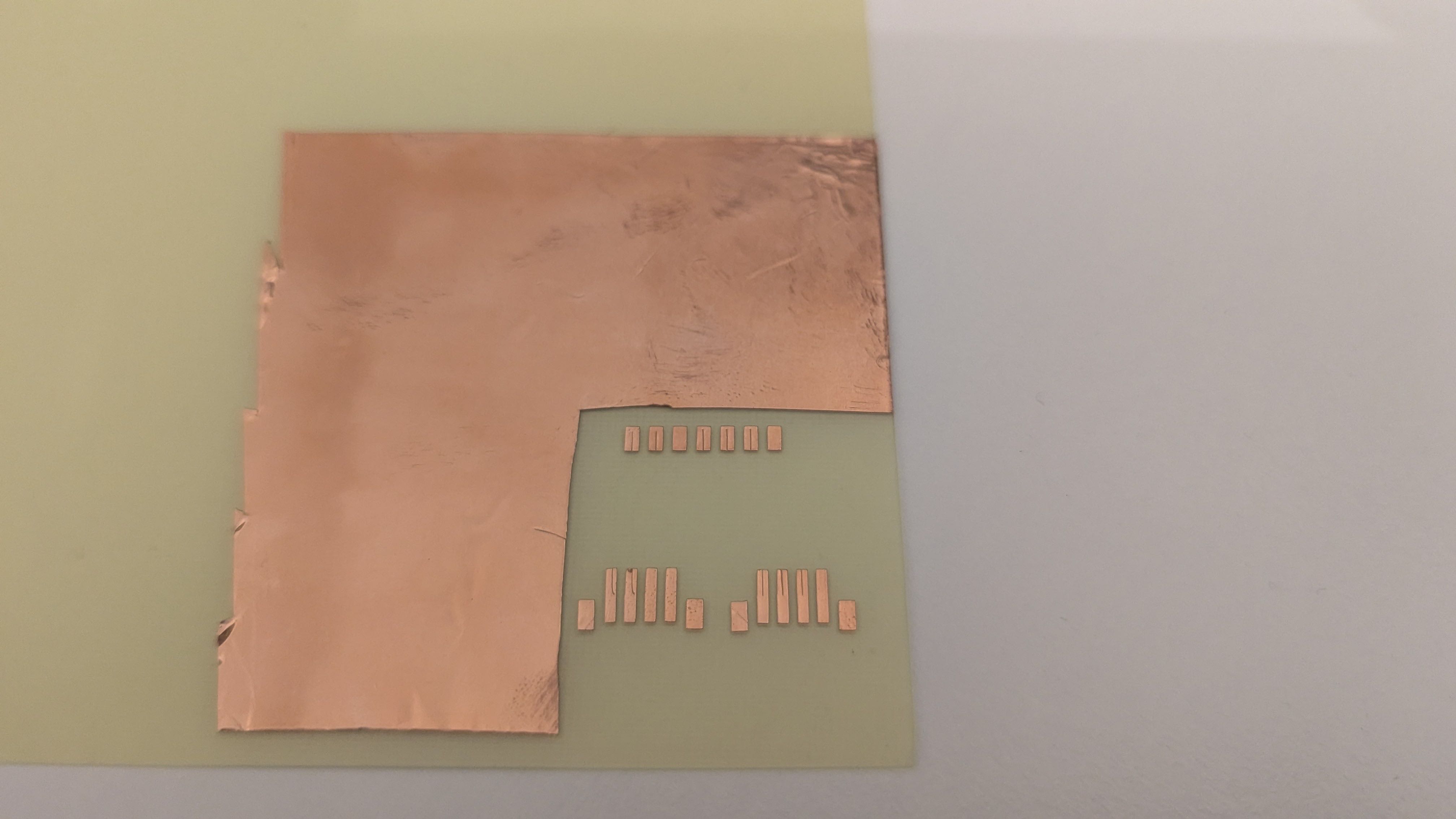
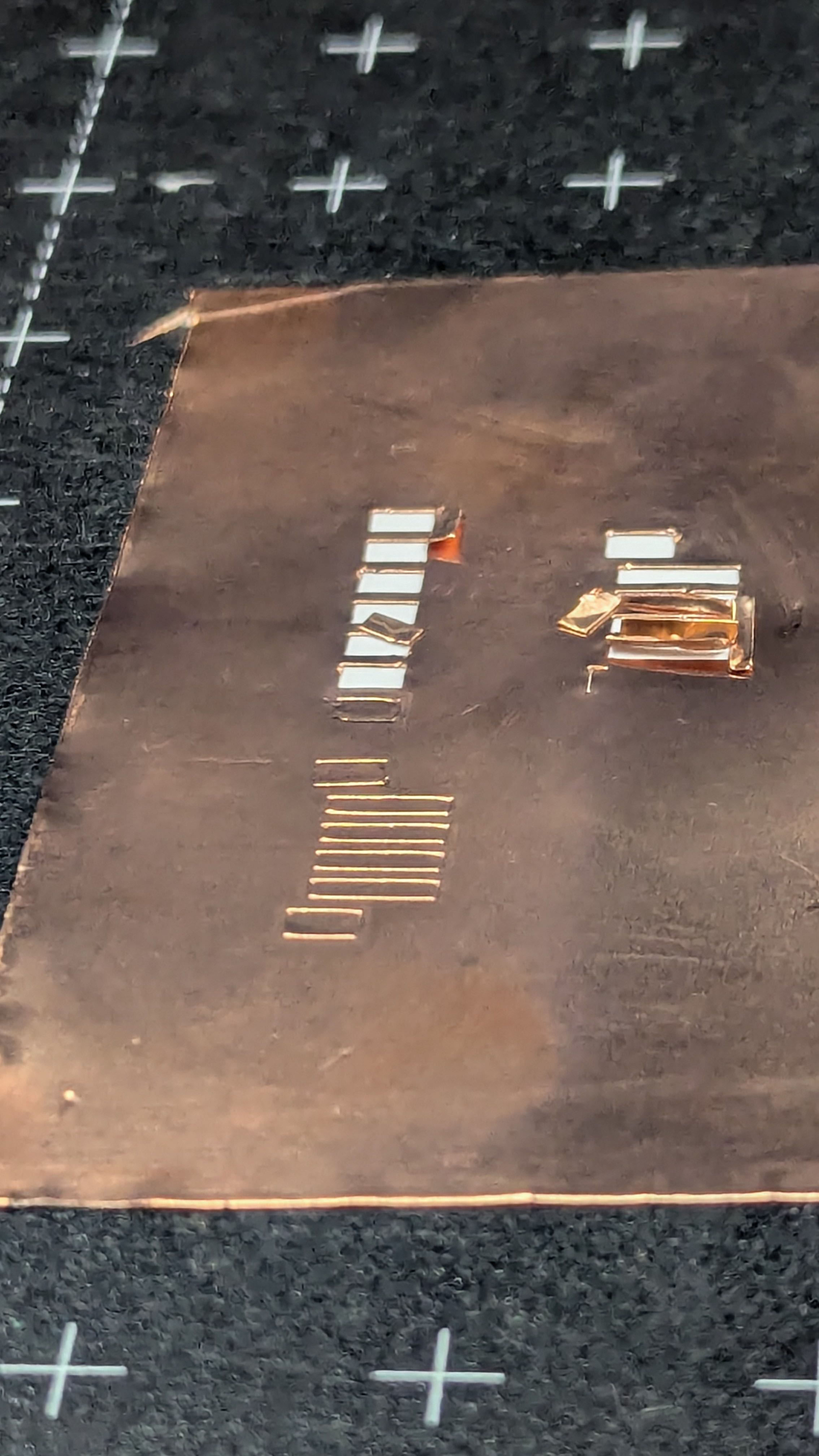
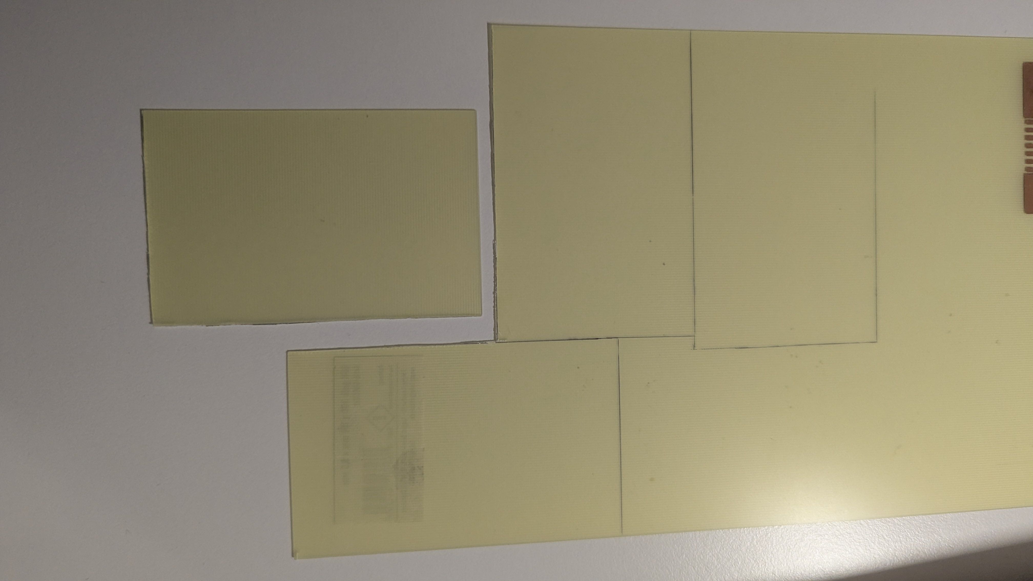
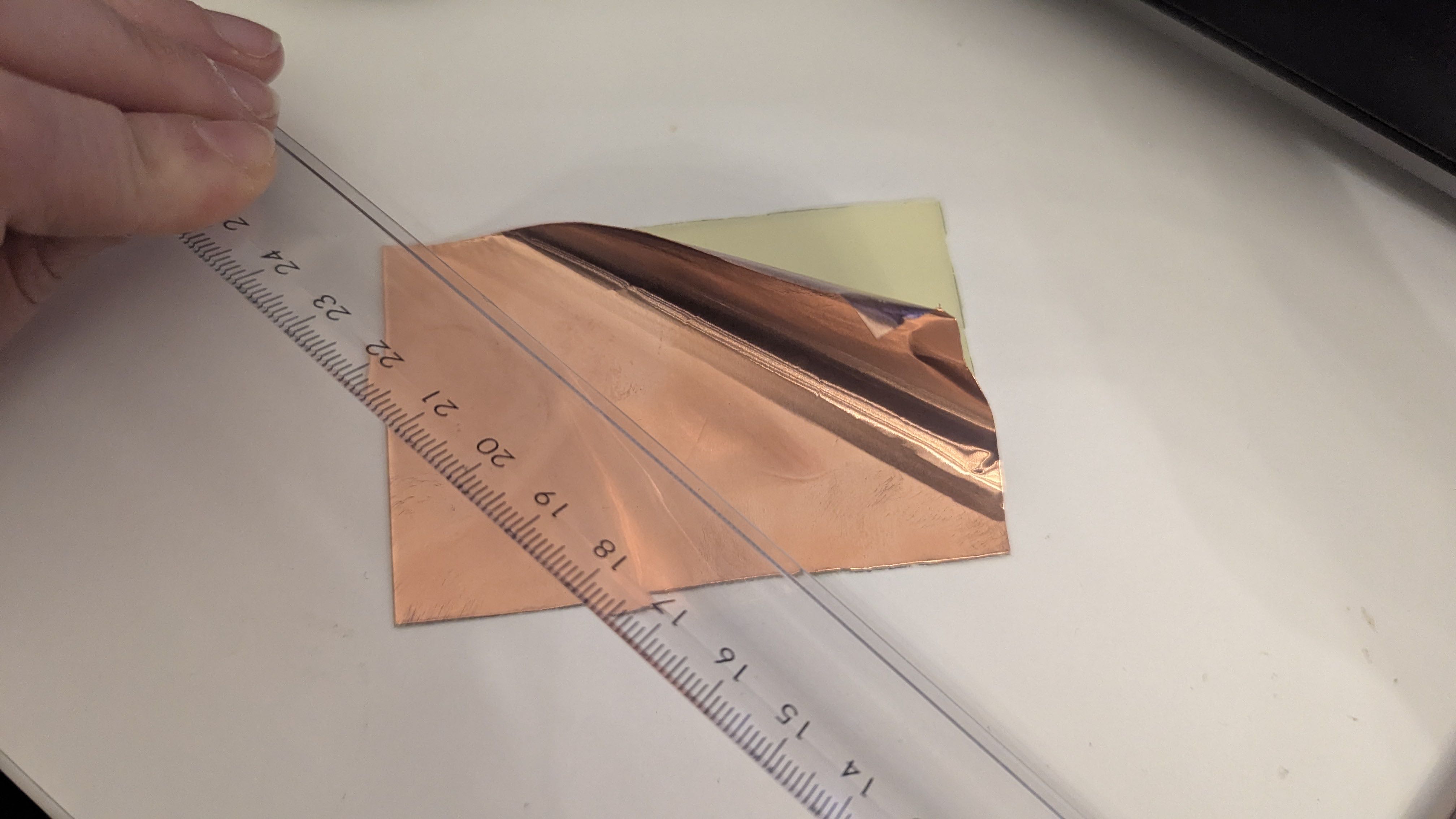
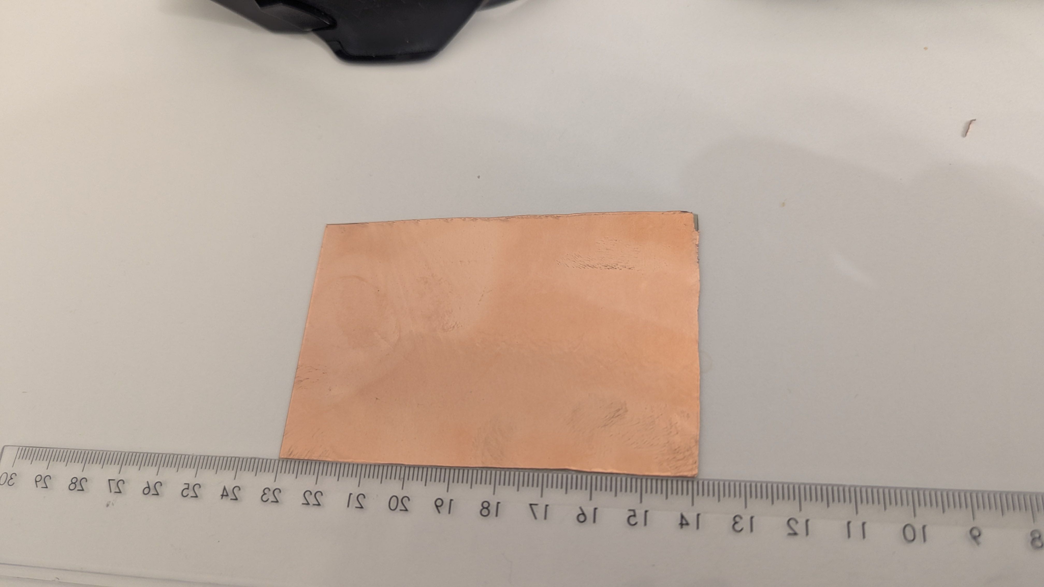
Fortunately, this looked promising, so I started cutting the FR4 sheets to the right size and applied the copper foil onto the cut pieces.
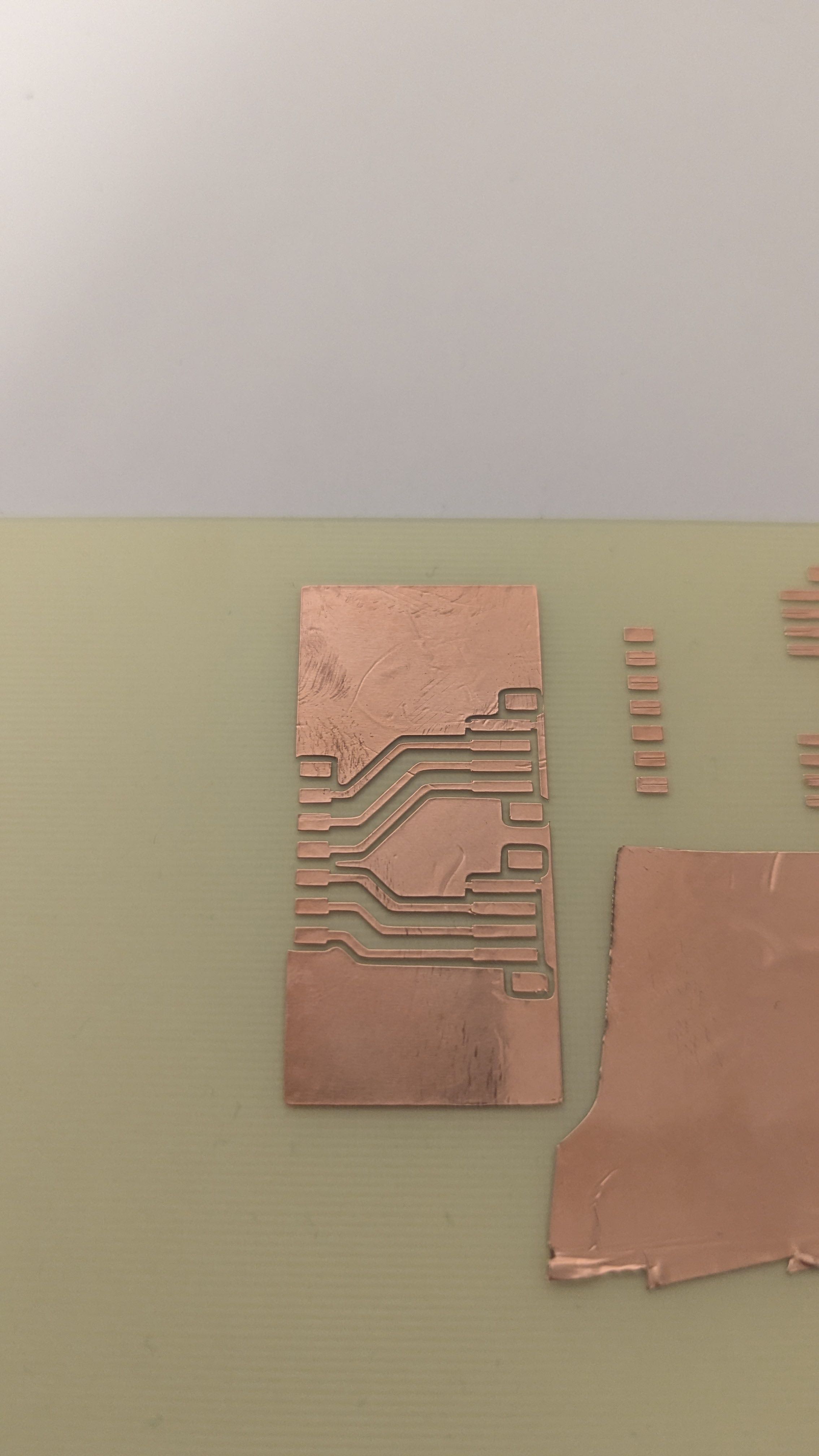
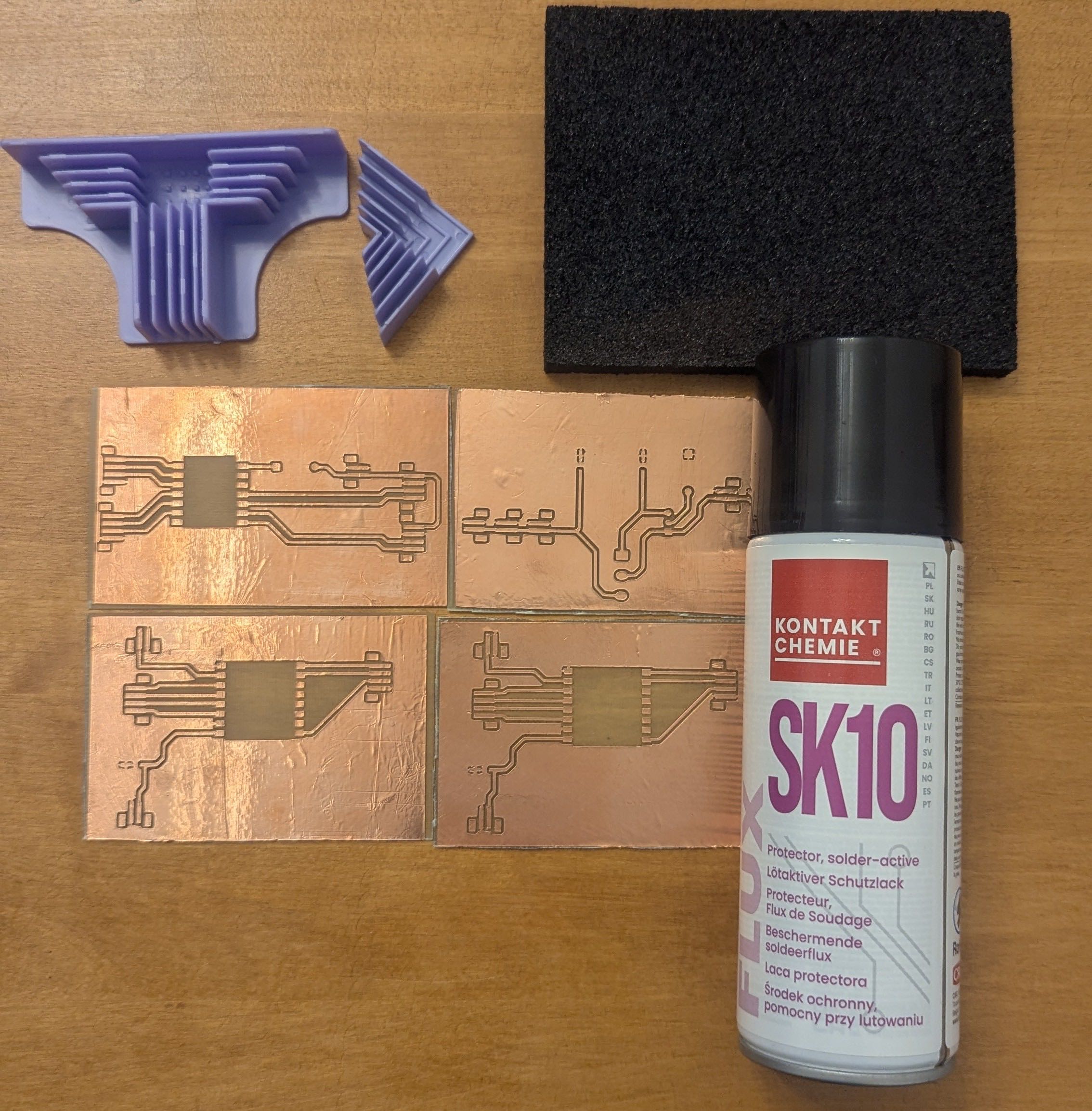
After plotting the copper foil I removed the unwanted parts.
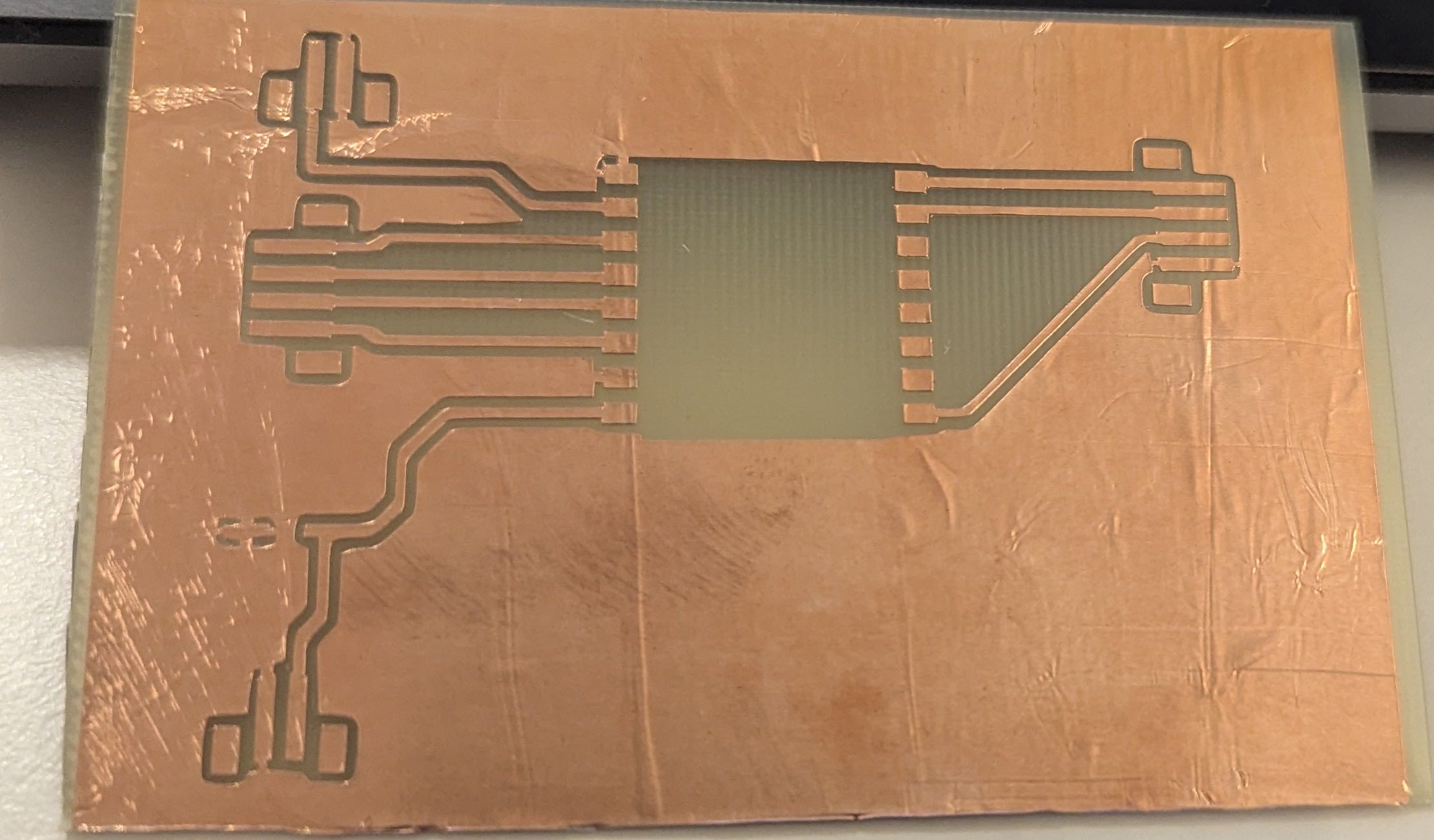
Out of curiosity, I placed the components on the circuit board and saw that they fit.
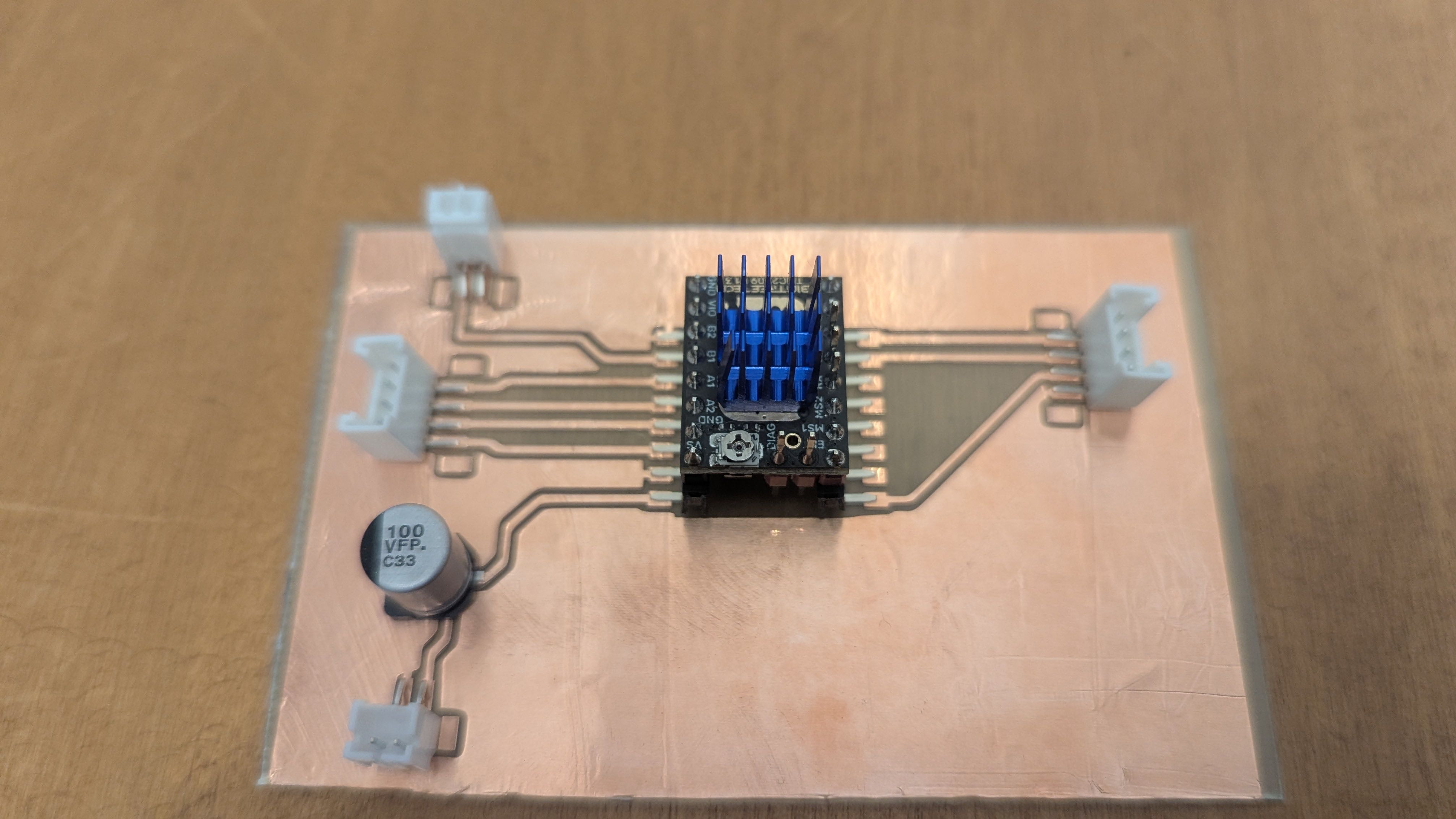
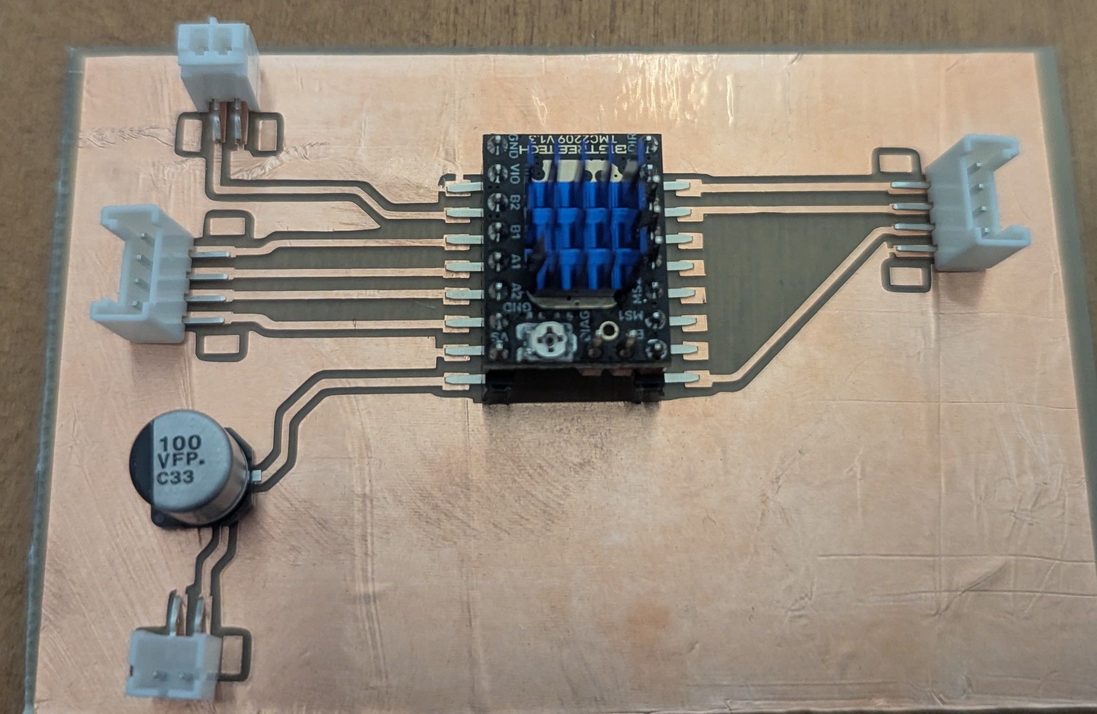
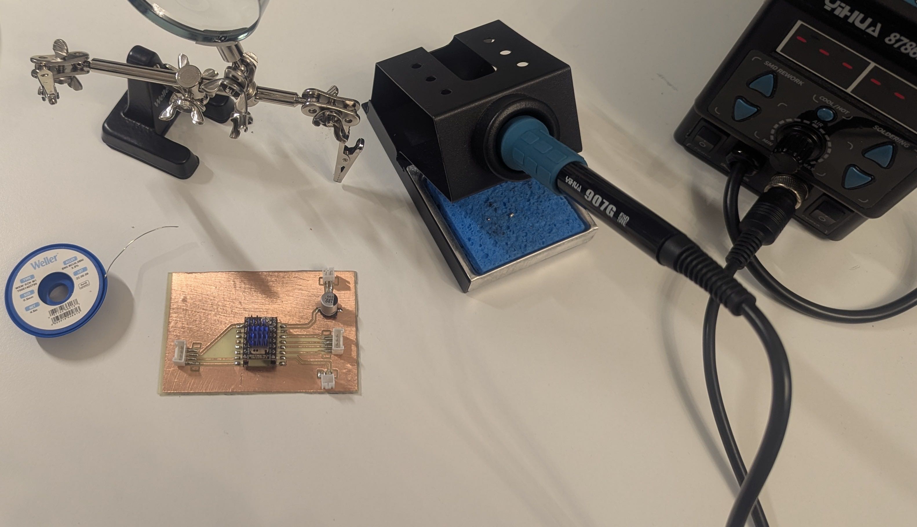
After manufacturing the PCBs, I had to prepare them for soldering. To do this, I sanded down the copper foil and applied solder mask to the PCBs.
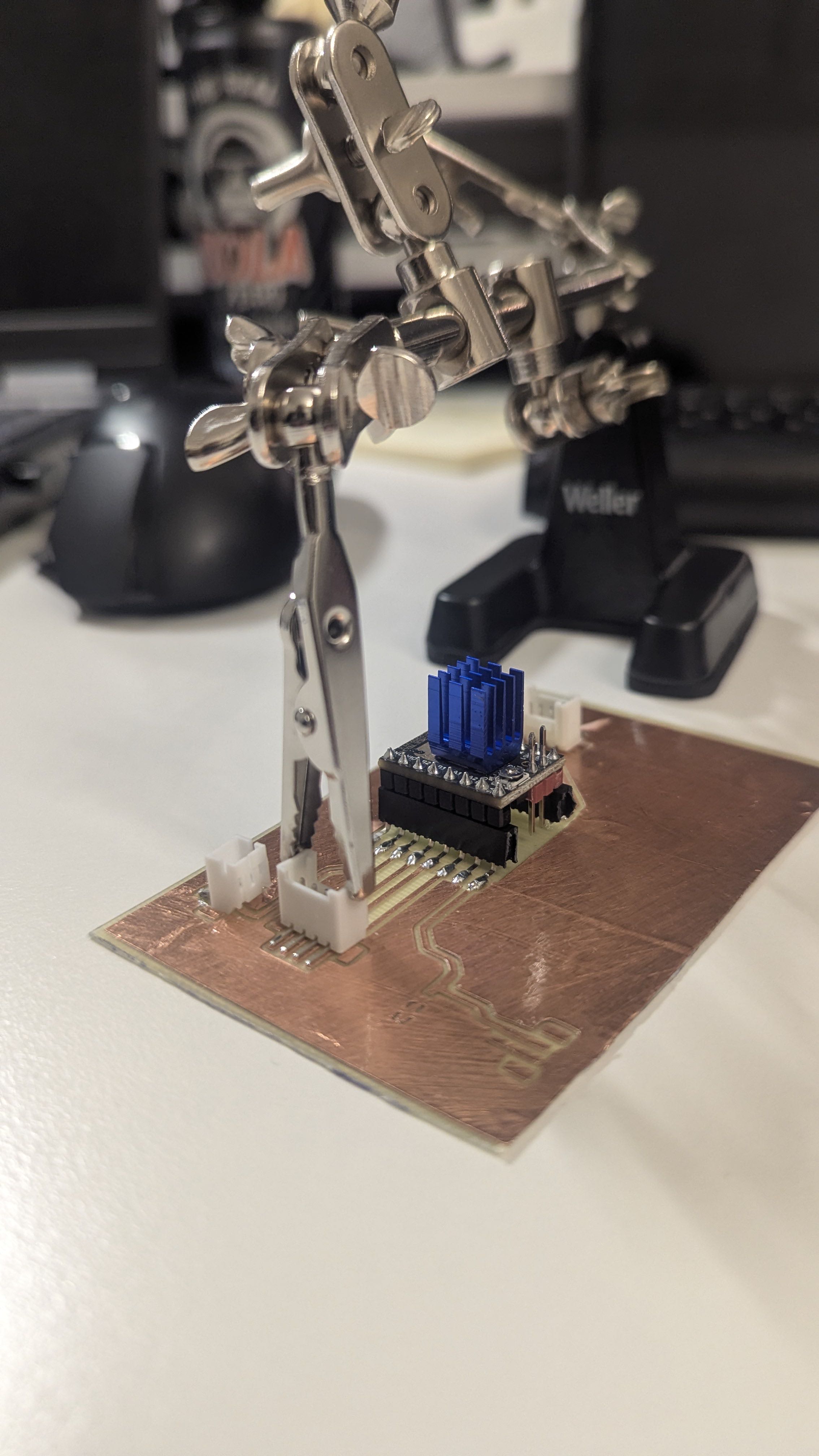
Then I soldered the components onto the circuit boards.
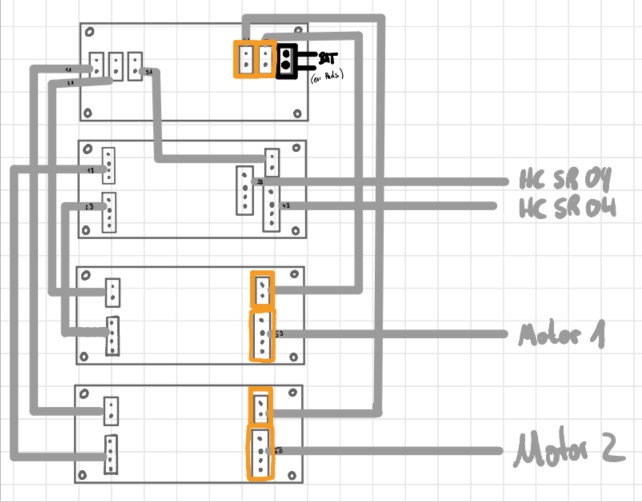
Cable Management
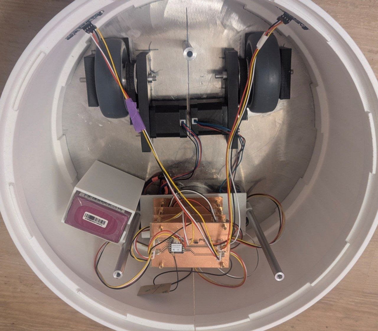
The four PCBs (power supply board, two motor driver boards and the ESP32 controller board) are stacked on standoffs as a modular PCB tower, which keeps the wiring compact and organized inside the enclosure. The boards are interconnected using JST connectors throughout, which allow individual boards to be disconnected and swapped out easily if needed. A detailed overview of the wiring and connector layout can be found on the System Integration page.
Programming
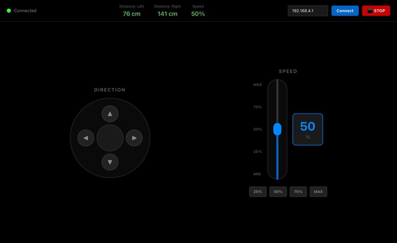
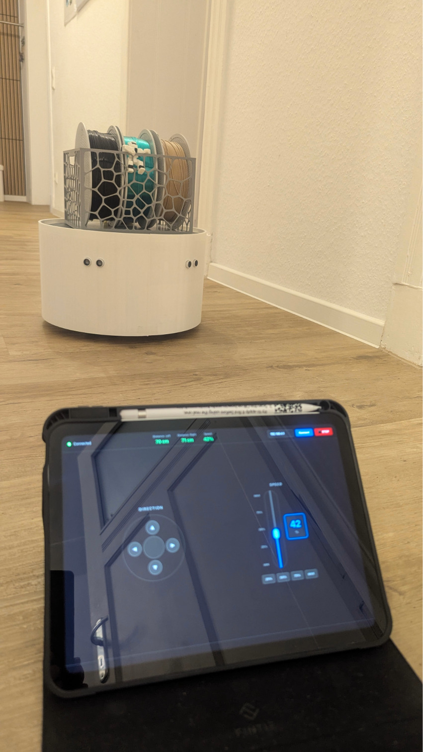
The firmware running on the XIAO ESP32S3 handles motor control via the TMC2209 drivers, obstacle avoidance using the HC-SR04 sensors and communication with the app over WiFi. The ESP32 runs as a WiFi access point and accepts HTTP GET requests from the app for direction and speed commands. The React Native controller app features a joystick-style direction pad, a speed slider with quick-select buttons, live sensor readings and an emergency stop button. A detailed description of both the firmware and the app development process can be found in Week 14 – Interface and Application Programming.
Firmware (ESP32S3)
React Native App
Assembly
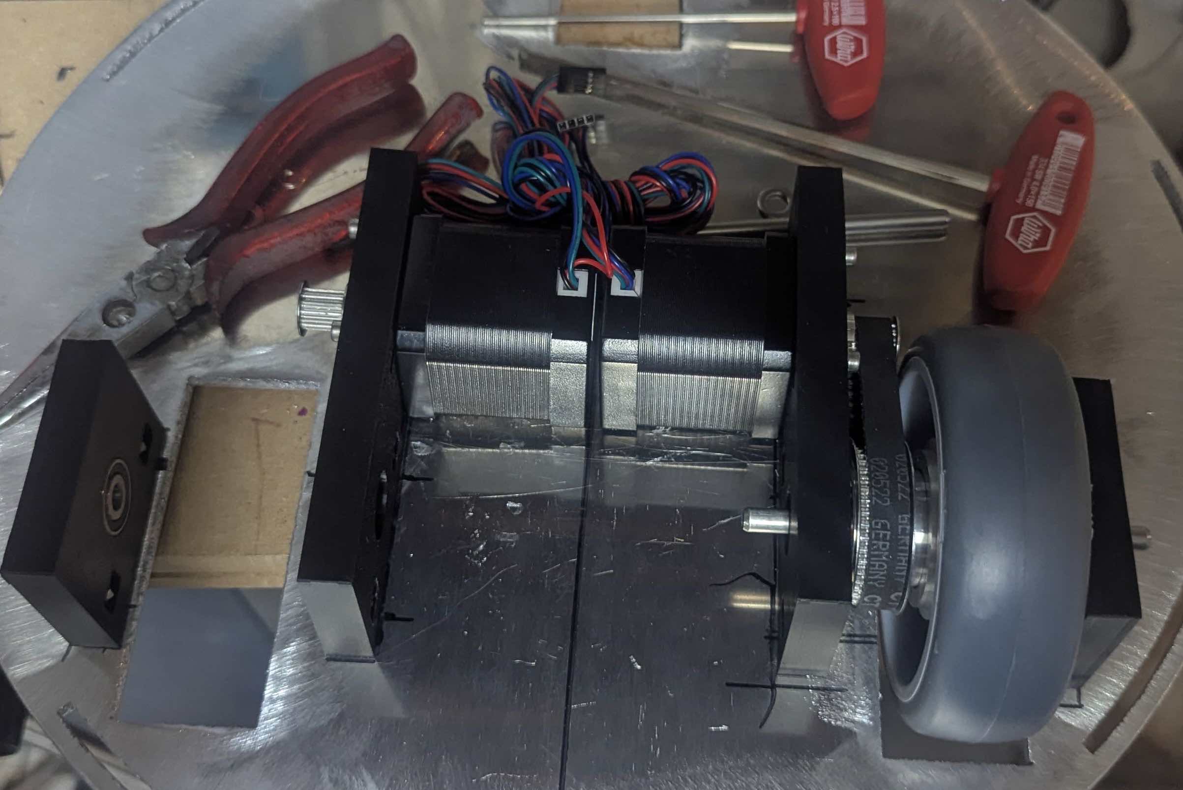
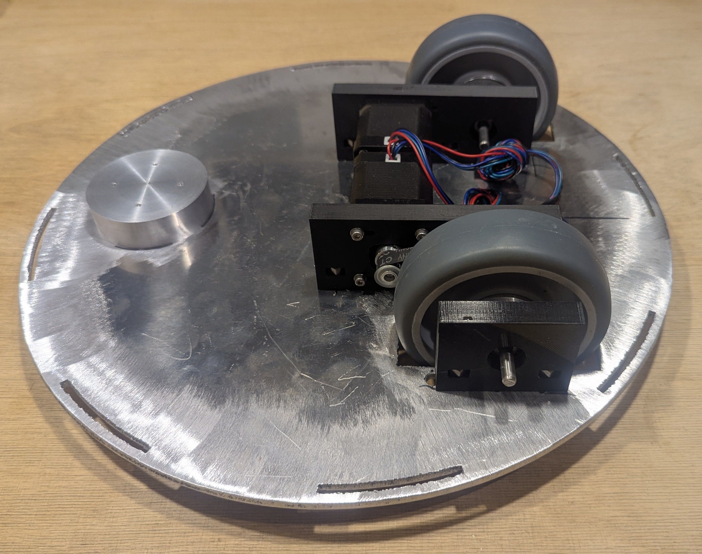
The assembly process started with mounting the drive units (bearing blocks, motors and belt construction) to the base plate, followed by connecting the bottom plate with the aluminum rods.
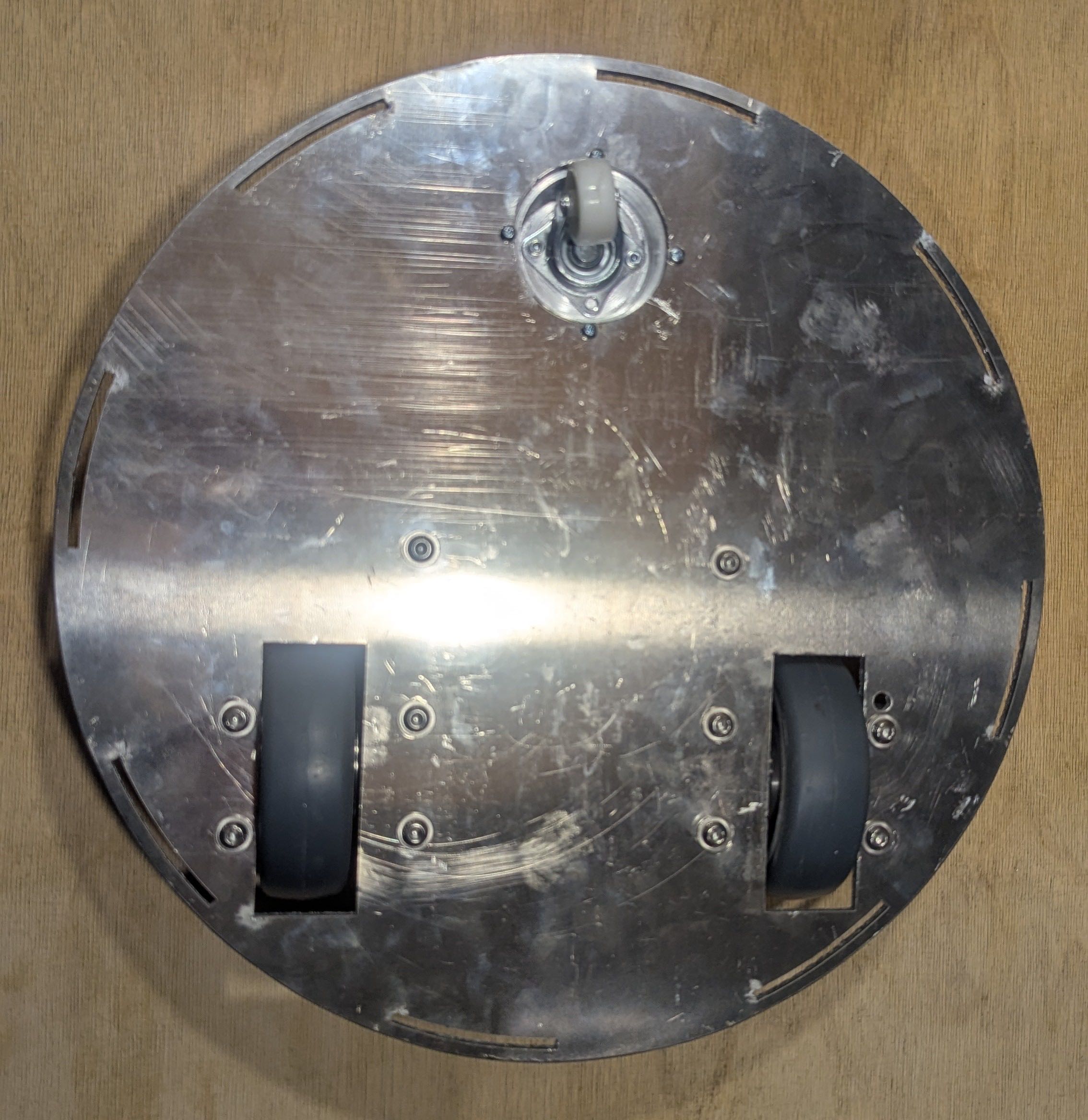
For mounting the aluminum rods that connect the plates for stability I had to drill holes inside the plate.
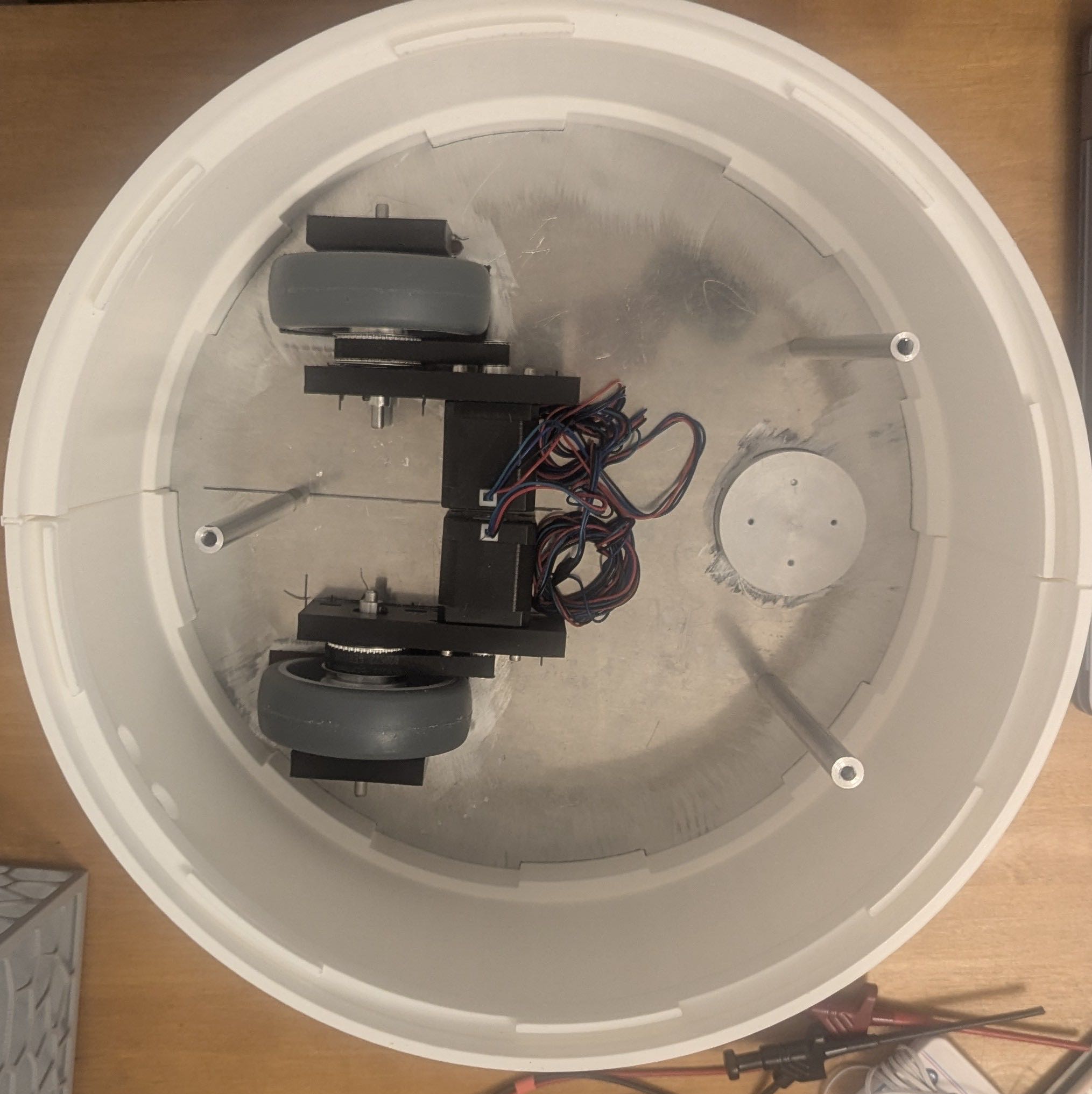
Afterwards I installed the electronics, PCB Tower and battery holder as described in Week 15 - System Integration.
And here is the final assembly of the system integration without top plate:
Testing
Testing was carried out in several stages, gradually adding complexity at each step.
Stage 1 – Ultrasonic Sensors
The first test of the ultrasonic sensors was carried out in Week 9 – Input Devices, where two HC-SR04 sensors were connected to the ESP32 and distance values were successfully output to the serial monitor.
Stage 2 – First Motor Test (DRV8825)
The drive unit was tested for the first time using the DRV8825 motor drivers with a fixed firmware program — no app communication involved. The left and right wheels were driven alternately to verify correct wiring and direction.
Stage 3 – Both Motors via App (DRV8825)
The first attempt to control both motors simultaneously via the app revealed a problem: the DRV8825 drivers were being blocked by the webserver, causing the motors to run intermittently rather than continuously, which also produced noticeable noise.
Stage 4 – Switch to TMC2209
Replacing the DRV8825 with the TMC2209 drivers solved the issue immediately. Both motors ran smoothly and quietly when controlled via the app.
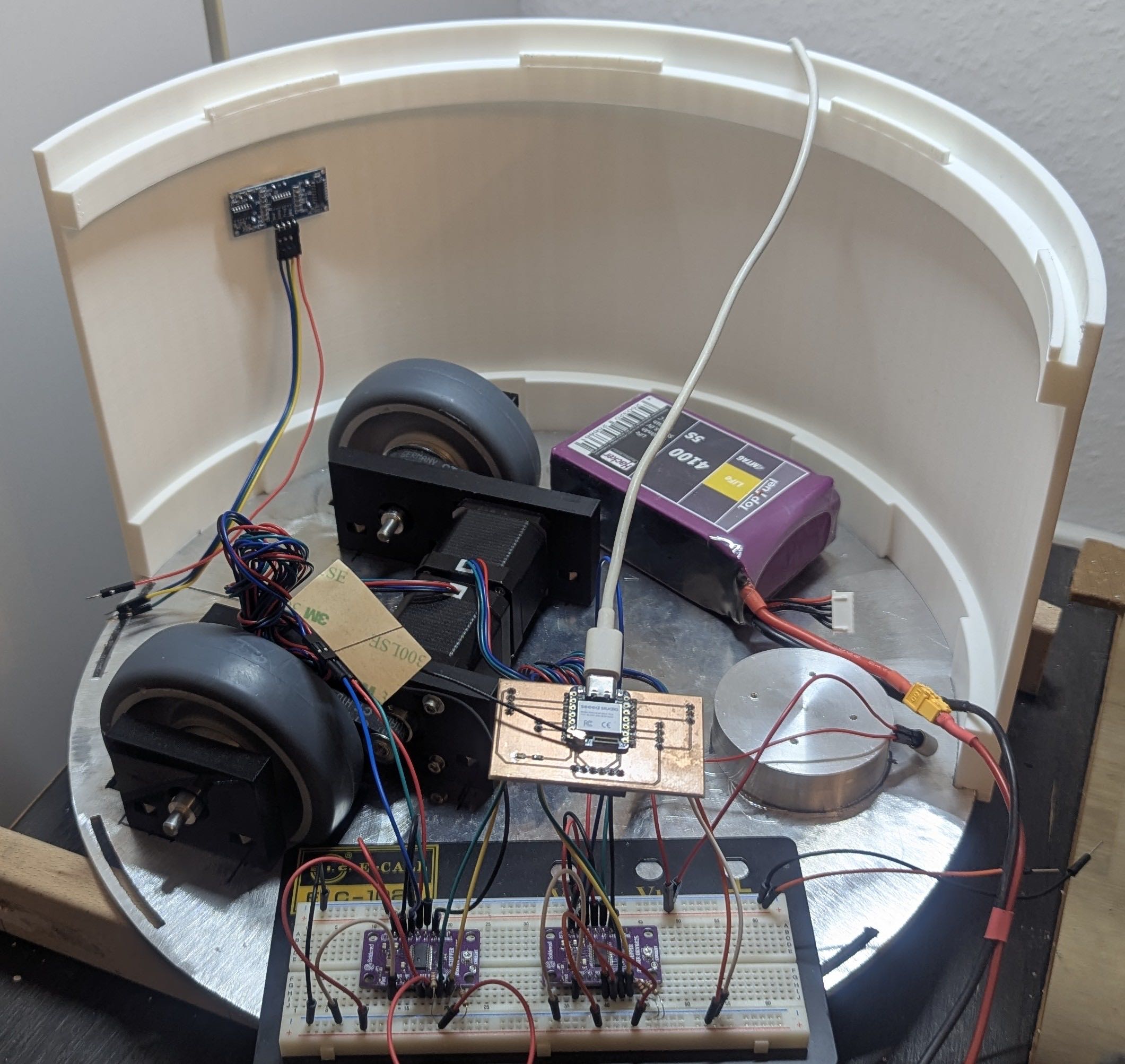
Stage 5 – Full Breadboard Test with App Control
The complete electronics were assembled on a breadboard and tested with app control for the first time. Including direction control (two directions of the remote in this video are wrong) and the app was without speed regulation yet.
Stage 6 – Testing the robot and the obstacle avoidance
After the full evaluation of the concept, I tested the final version of the robot with speed control and the obstacle avoidance. That was the point where I had to adjust the parameters of the obstacle avoidance because it is better if the robot has more space to avoid the obstacle smoothly and not run into full stop mode.
Stage 7 – Final Drive
After testing all the subsystems I did a final drive with 3kg payload. I was always curious how much payload my robot will be able to carry. I think it will be significantly more due to its stable construction - it has a weight of 5.7kg itself.
Design Files
| File | Format | Download |
|---|---|---|
| Bottom Plate | .dxf | 📎 Download |
| Top Plate | .dxf | 📎 Download |
| Enclosure Part A | .3mf | 📎 Download |
| Enclosure Part B | .3mf | 📎 Download |
| Basket | .3mf | 📎 Download |
| Bearing Block Large (Side 1) | .3mf | 📎 Download |
| Bearing Block Large (Side 2) | .3mf | 📎 Download |
| Bearing Block Small | .3mf | 📎 Download |
| Seam | .3mf | 📎 Download |
| Battery Holder | .3mf | 📎 Download |
| PCB Files | .zip | 📎 Download |
| Firmware | .ino | 📎 Download |
| App Source | .zip | 📎 Download |
| App APK | .apk | 📎 Download |