Week 15 - System Integration
 Edited on: June 10, 2026
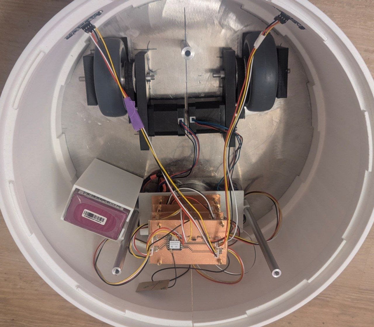
My final project RoboBuddy consists of various subsystems: two motor driver PCBs, a power supply board, an obstacle avoidance and controller board hosting the ESP32S3, as well as mechanical parts including the belt-driven drivetrain with two stepper motors, the 3D-printed enclosure, and the magnetic basket.
Subsystems overview: - Mechanics (chassis, belt drive, wheels) - Electronics (PCB tower, sensors, motors) - Power (battery, battery enclosure) - Firmware (ESP32S3, motor control, obstacle avoidance) - App (React Native, WiFi AP hosted by ESP32S3)
System Integration Plan
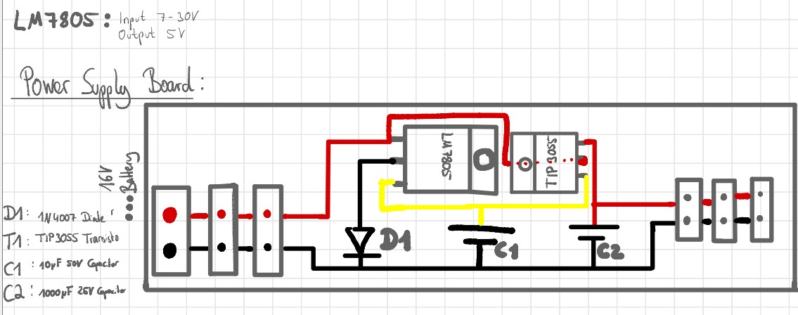
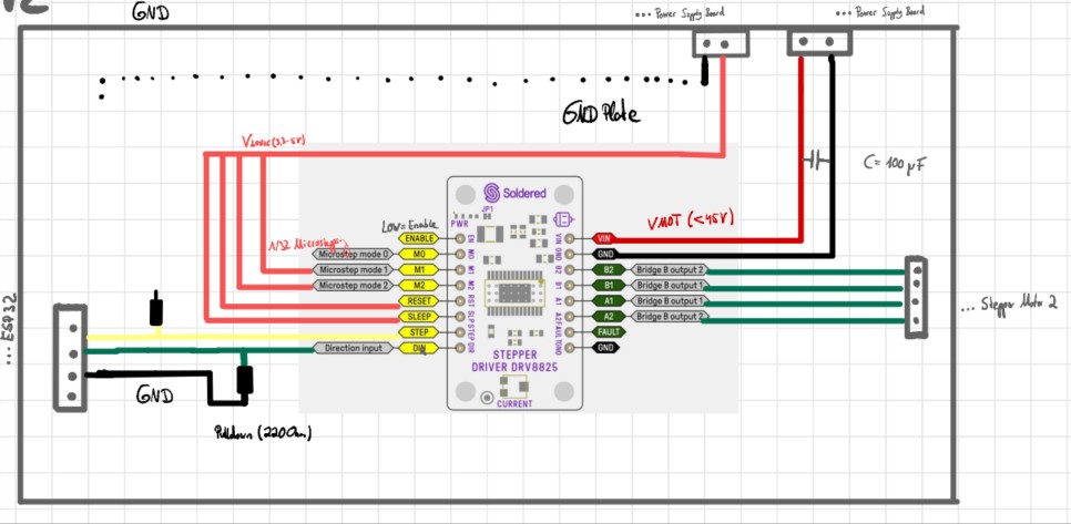
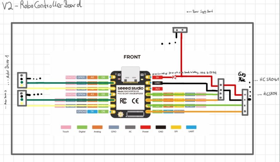
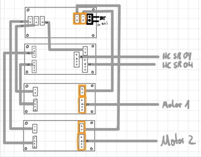
After the prototyping phase I drew sketches for the wiring of the different subsystems to organize the connections in a clean way. Note that these sketches still reference the DRV8825 motor drivers, which I later replaced with the TMC2209: a quieter and more reliable alternative that caused significantly less trouble during the machine building week.
Mechanical Integration
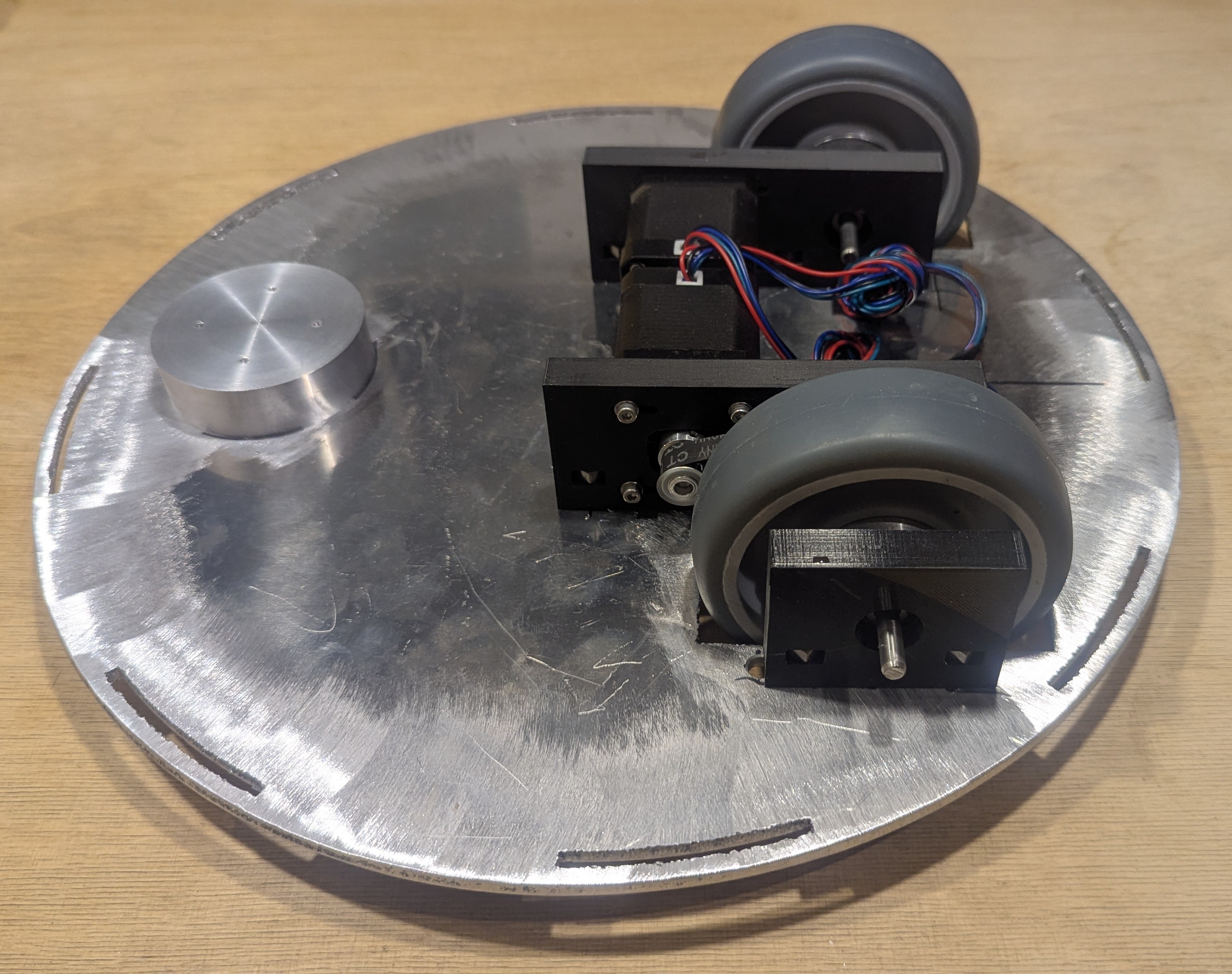
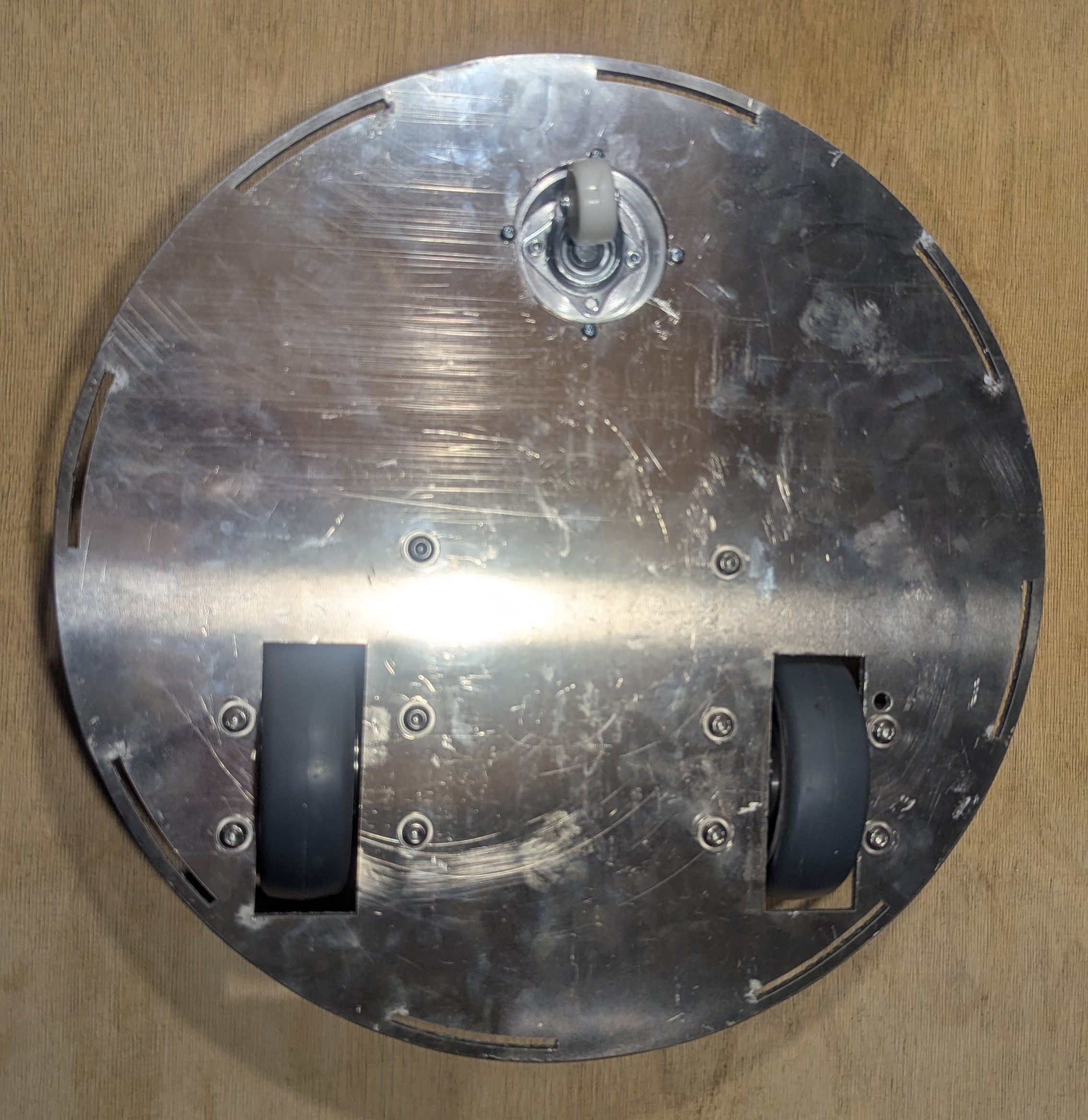
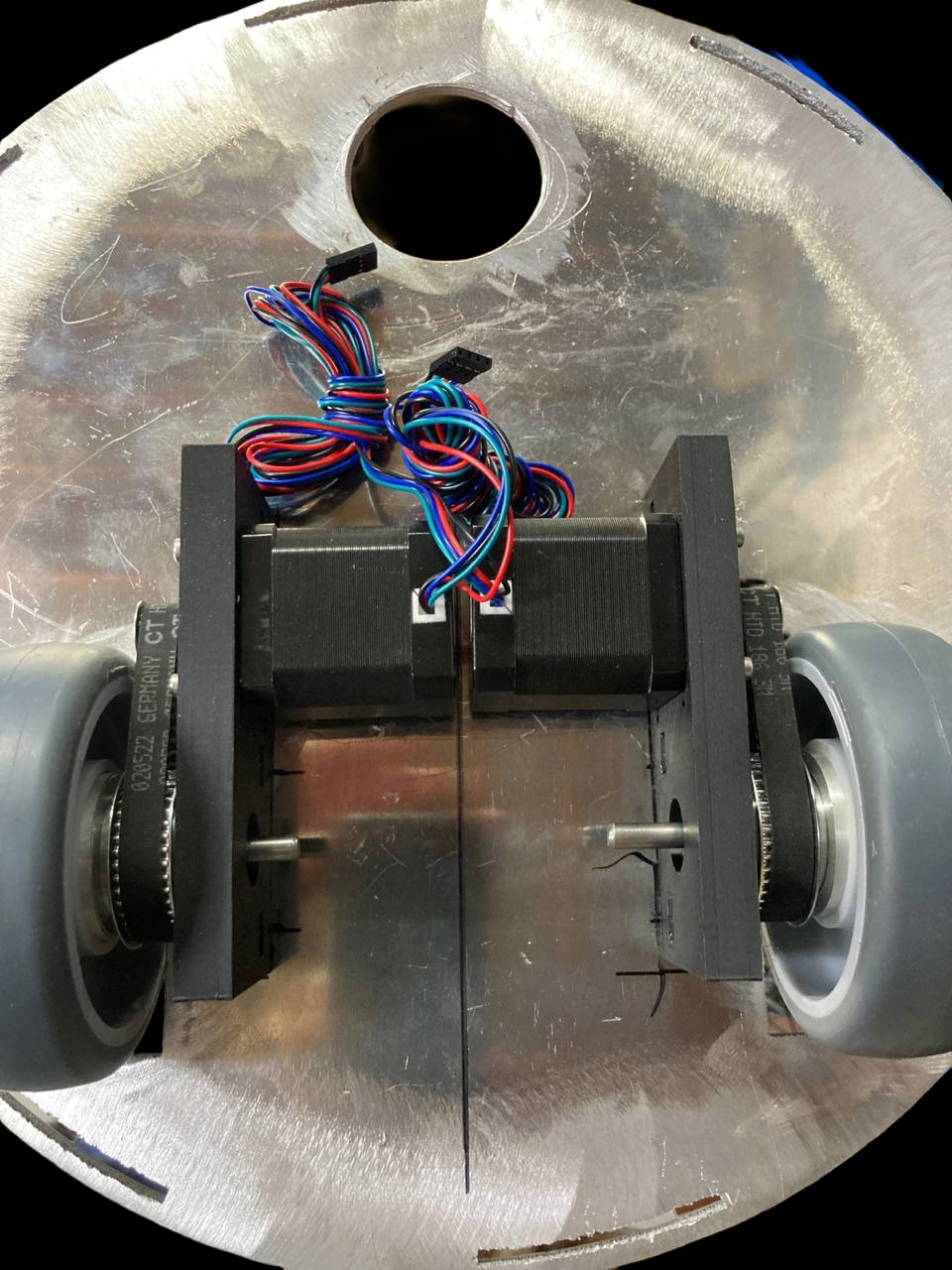
The mechanical integration of the belt drivetrain and enclosure was completed in a previous week. Detailed documentation can be found on the Final Project page. In summary, the assembly steps were:
- Mounting the bearing blocks and motors to the base plate
- Mounting the drive wheels and 360° omni wheel
- Printing and fitting the enclosure
- Connecting the inner rods to the base plate for structural stability
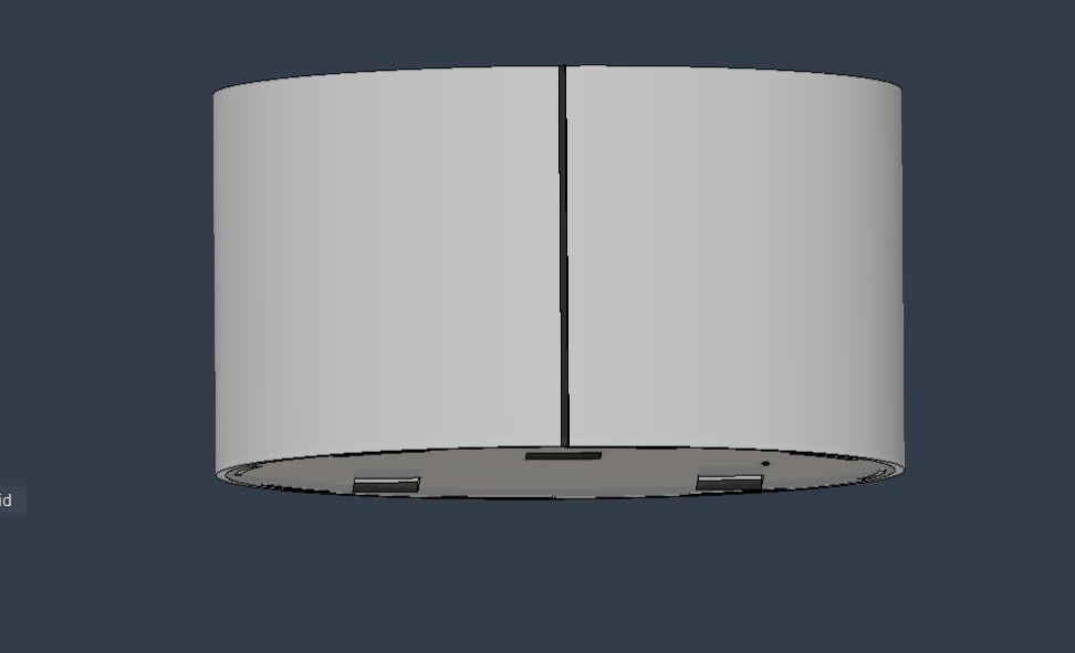
This week I added a seam to the enclosure for a cleaner finish and to prevent light leakage between the printed parts.
 -
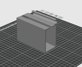
- Battery Holder
To keep the battery securely in place, I designed and printed a dedicated battery holder that attaches to one of the inner rods at the same fixing point as the PCB tower.
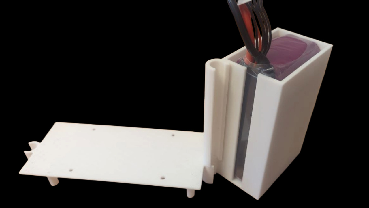 -
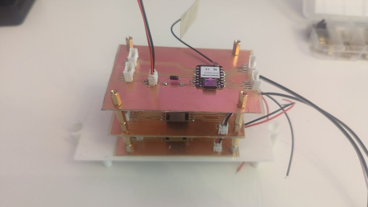
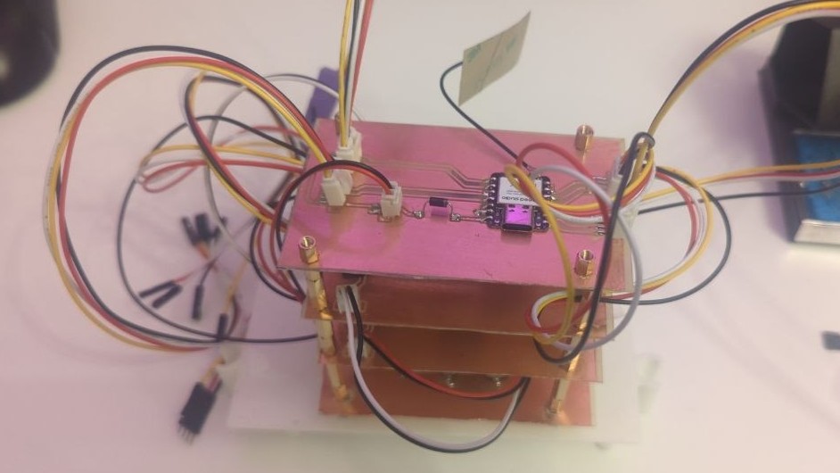
- PCB Tower
I chose a modular PCB tower design so that individual boards can be swapped out easily if needed. The tower is mounted on a printed base plate that connects to the inner rods of the chassis, keeping everything fixed and preventing movement inside the enclosure.
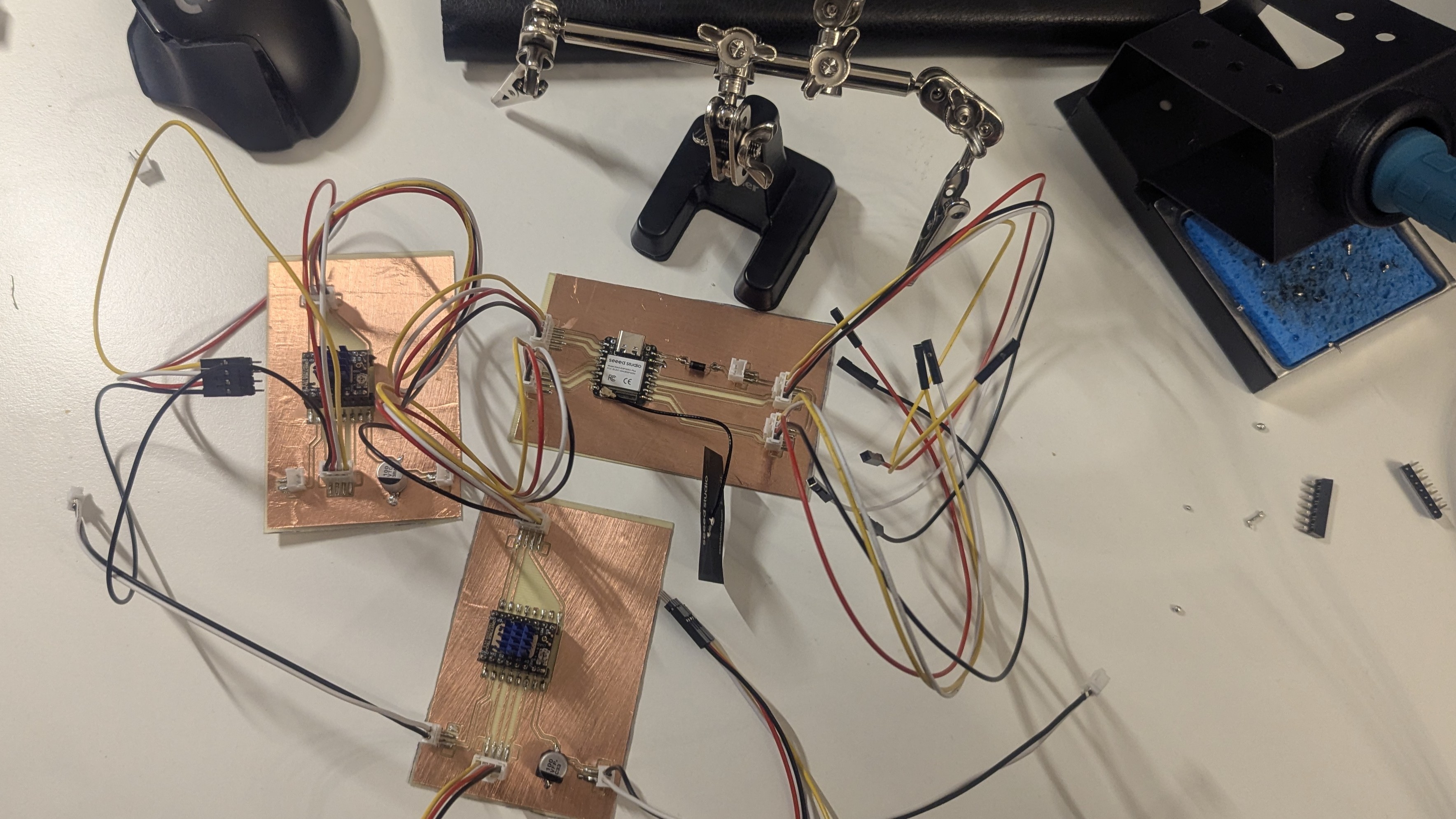
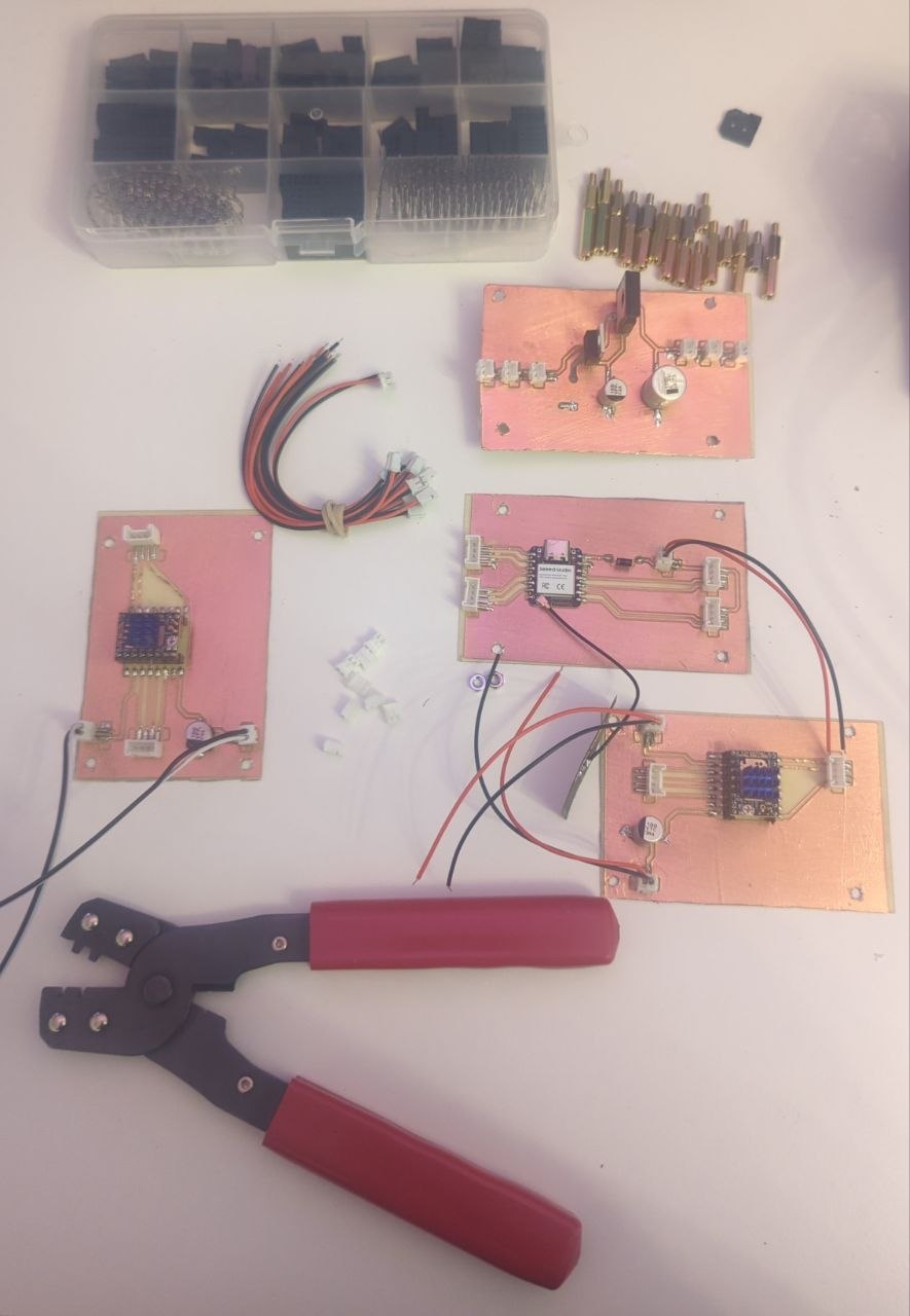
Electrical Integration
All boards are connected as follows:
- ESP32S3 → TMC2209 (left motor)
- ESP32S3 → TMC2209 (right motor)
- TMC2209 → Stepper motors
- ESP32S3 → HC-SR04 ultrasonic sensors
- Battery → Power distribution board → all PCBs
Connector types used: JST and Dupont connectors throughout. You can see the entire process of the PCB manufacturing on the final project page.
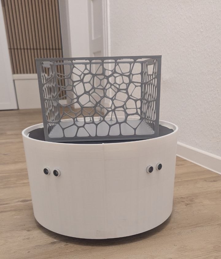
Final Result
The fully assembled RoboBuddy with all subsystems integrated, wired and enclosed in the finished housing.