Week 17 - Applications and Implications / Project Development
Published on: June 03, 2025 Updated on: April 11, 2026
Project Summary
My final project is a companion robot named Robo-Buddy, which follows its owner and can carry items. It integrates mechanical construction, electronics design, embedded systems, and digital fabrication techniques. The robot includes remote control functionality and sensor-based obstacle detection and avoidance and will serve as a modular base for future expansions like autonomous behaviors.
What will it do?
The robot will follow its user, avoid obstacles, and transport personal belongings. It uses stepper motors, ultrasonic sensors, and wireless communication (WiFi). It is controlled via a mobile app and features modular construction for upgrades.
Who has done what beforehand?
Projects such as R2D2 builds or autonomous delivery robots have inspired this concept. However, Robo-Buddy aims to combine practical mobility with modular extensibility using digital fabrication techniques and low-cost electronics.
What will you design?
- Chassis (top & bottom plate – laser cut from aluminum)
- Bearing blocks and mounts (3D printed)
- Electronics PCBs for motor drivers and ultrasonic sensors
- 3D printed housing and basket for aesthetic design
- Mobile App for basic control
Bill of Materials (BOM)
| # | Article | Qty | Source | Price (€) | Shop | Notes |
|---|---|---|---|---|---|---|
| 1 | Copper-clad PCB / FR4 Plates | 2 | Lab Stock | 0 | ||
| 2 | Aluminum plate (chassis) | 1 | Lab Stock | 0 | ||
| 3 | Steel rod 6mm (wheel axle) | 1 | Lab Stock | 0 | ||
| 4 | PETG Filament | ~1000g | Lab Stock | 0 | ||
| 5 | Self-adhesive copper foil (2000x300x0.07mm) | 1 | Lab Stock | 0 | ||
| 6 | XIAO ESP32-S3 Plus | 1 | Reichelt | 9,99 | Shop | |
| 7 | Joy It Nema17 Stepper Motor | 2 | Reichelt | 42,40 | Shop | |
| 8 | TMC2209 BigTree v1.3 | 2 | roboter-bausatz.de | 13,56 | Shop | |
| 9 | DRV8825 (soldered) | 2 | Reichelt | 15,90 | Shop | obsolete |
| 10 | HC-SR04 Ultrasonic Sensor | 2 | Reichelt | 6,90 | Shop | |
| 11 | Hacker LiFe Akku 4100mAh 5S | 1 | flashrc.com | 169,90 | Shop | |
| 12 | Timing Belt | 2 | Z24 | 22,96 | Shop | |
| 13 | Timing Belt Pulley | 2 | Z24 | 28,60 | Shop | |
| 14 | Ball Bearings | 4 | Z24 | 7,60 | Shop | |
| 15 | Rod (6mm) | 2 | Z24 | 21,82 | Shop | |
| 16 | 8-Pin 2.54mm Header (Female SMD) | 4 | Reichelt | 2,60 | Shop | |
| 17 | 2-Pin Connector (Female SMD 90°) | 10 | Reichelt | 5,20 | Shop | |
| 18 | 4-Pin Connector (Female SMD) | 8 | Reichelt | 6,80 | Shop | |
| 19 | 2-Wire Cable (M-M) | 5 | Eckstein-Shop | 5,95 | Shop | |
| 20 | 4-Wire Cable with 2.54mm Jumper (Male) | 2 | Reichelt | 5,98 | Shop | |
| 21 | Ribbon Cable | 1 | Reichelt | 3,10 | Shop | |
| 22 | Male Dupont Connectors (crimping set) | 8 | Reichelt | 9,75 | Shop | |
| 23 | Diode 1N4007 | 2 | Reichelt | 0,06 | Shop | |
| 24 | TIP3055 Transistor | 1 | Reichelt | 2,99 | Shop | |
| 25 | LM7805 Voltage Regulator | 1 | Reichelt | 1,40 | Shop | |
| 26 | Capacitor 10uF 50V | 1 | Reichelt | 0,46 | Shop | |
| 27 | Capacitor 1000uF 25V | 1 | Reichelt | 0,38 | Shop | |
| 28 | Capacitor 100uF | 2 | Reichelt | 0,50 | Shop | |
| 29 | Resistor 220 Ohm | 4 | Reichelt | 0,28 | Shop | |
| 30 | Power Switch | 1 | Reichelt | 1,60 | Shop | |
| 31 | Screws, nuts, spacers | - | Hornbach | 20,00 | ||
| 32 | Black Spray Paint | 1 | Hornbach | 9,90€ | Shop | |
| 33 | JST PH CKB | 50 | 2,50€ | Shop | ||
| 34 | JST PH2P BU | 30 | 1,50€ | Shop | ||
| 35 | JST PH4P BU | 20 | 1,00€ | Shop | ||
| 36 | Wheel | 2 | ebay | 6,50€ | Shop | |
| 37 | Multi-Wheel | 1 | ebay | 2,40€ | Shop | |
| 38 | Rod 10mm * 180mm | 3 | Z24 | 19,06€ | Shop |
Where will they come from?
A combination of locally available materials and online-sourced components will be used in this project. Copper-clad PCB sheets, the aluminum plate for the chassis, and the steel rod used for the wheel axle were sourced from the Fab Lab inventory. Components like the NEMA 17 stepper motors, motor driver modules, ultrasonic sensors, XIAO ESP32S3Plus and cables were sourced from Reichelt Elektronik. This approach helps balance cost-efficiency with component availability and reuse of existing lab stock wherever possible.
How much will they cost?
The estimated cost is around 150€ - 250€, including all electronic parts and structural materials.
What parts and systems will be made?
- Metal chassis (laser cut)
- 3D printed bearing blocks
- Customized wheels with timing belt wheels made for heavy duty
- 3D printed components: mounts, dome, enclosure
- Custom PCBs for motor drivers and sensors
- Mobile control app and embedded firmware
What processes will be used?
- 2D Design (Inkscape, Fusion 360)
- 3D Design (Fusion 360)
- 3D Printing (FDM)
- Laser Cutting (Metal & Acrylic)
- Electronics design and milling (KiCad)
- Microcontroller programming (Arduino IDE, ESP32)
- App programming (MIT App Inventor)
What questions need to be answered?
- How can I ensure stable communication between modules?
- What is the optimal power source for long runtime?
- Will my mechanical design withstand the weight?
- Will the application be able to control the robot precisely?
- Can the mobile app be expanded for gesture or voice control?
How will it be evaluated?
- Can avoid obstacles using ultrasonic sensors
- Moves forward/backward and turns smoothly
- 3D printed housing fits correctly and looks clean
- Electronics are safe and modularly integrated
Progress Overview
| Task | Status |
|---|---|
| Design and 3D print bearing blocks | ✅ |
| Insert ball bearings into bearing blocks | ✅ |
| Manufacture drive wheels with belt pulleys | ✅ |
| Laser-cut top and bottom plates | ✅ |
| Purchase and integrate drive shafts | ✅ |
| Develop first version of control app | ✅ |
| Design and 3D print external casing | ❌ |
| Redesign motor driver PCB | ❌ |
| Redesign ultrasonic sensor PCB (GRV 4-pin) | ❌ |
| Integrate power supply and voltage regulation | ❌ |
Spiral Development Plan
The development of the Robo-Buddy is structured in iterative stages, each one delivering a working prototype and building toward the final functionality.
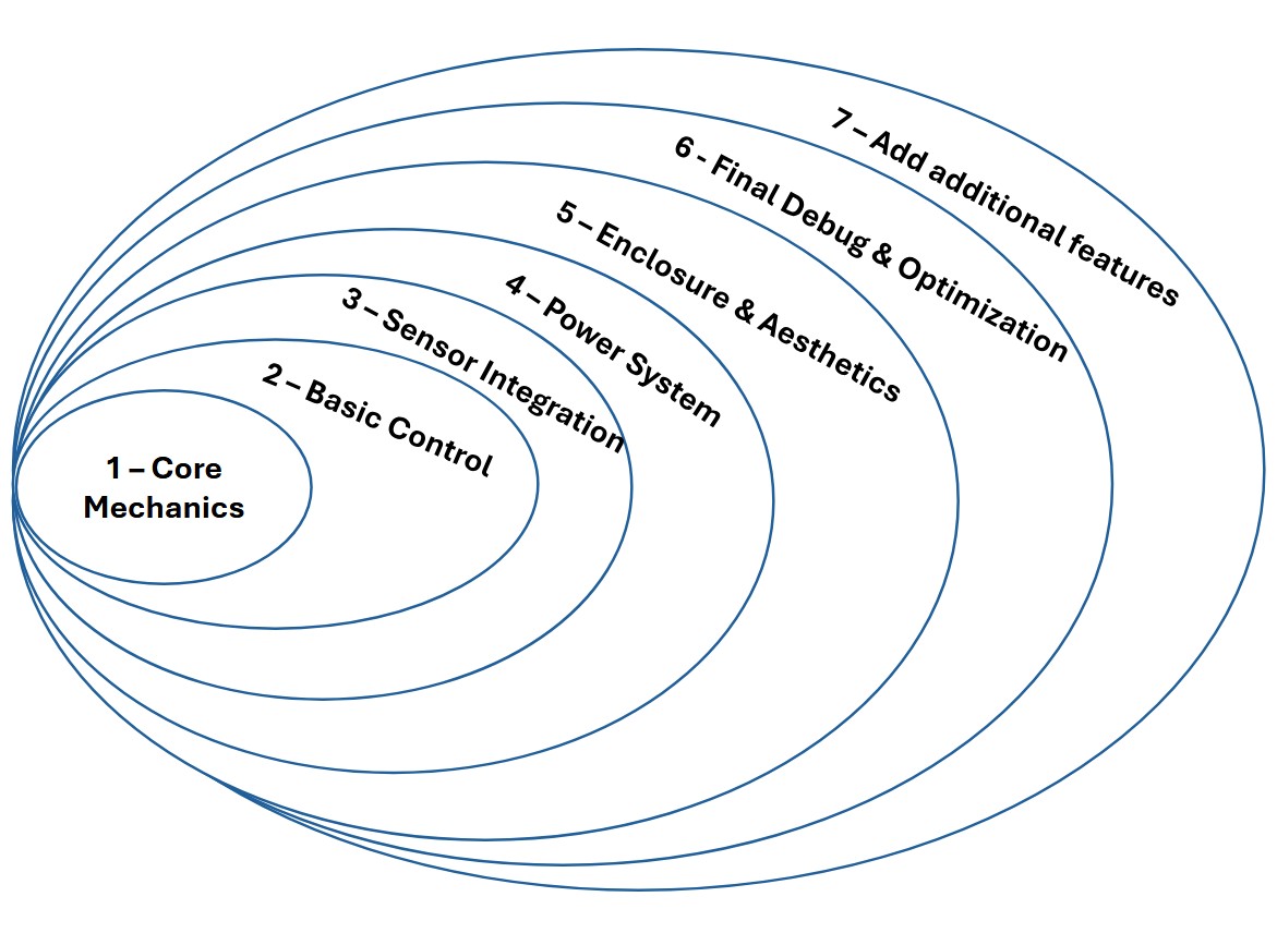
- Spiral 1 – Core Mechanics: Assembly of chassis, drive shafts, wheels, and bearing blocks. Ensure stable movement and structural integration.
- Spiral 2 – Basic Control: Implement remote control functionality using the smartphone app. Test basic movement: forward, backward, turn.
- Spiral 3 – Sensor Integration: Add and test obstacle detection using ultrasonic sensors using I2C between boards.
- Spiral 4 – Power System: Add final power supply, including voltage regulation and battery integration. Test full mobility.
- Spiral 5 – Enclosure & Aesthetics: 3D model and print the robot shell and integrate the dome, mounting slots, and covers.
- Spiral 6 – Final Debug & Optimization: Refine PCBs, clean wiring, stress-test interaction between modules, and prepare final documentation.
- Spiral 7 – Add additional features: Add features like RF- Follow Me - Mode.
What has been done?
| Status | Task |
|---|---|
| ✅ | Bearing blocks 3D printed |
| ✅ | Chassis plates laser-cut |
| ✅ | First PCB for ultrasonic sensors milled |
| ✅ | Drive shafts and wheels integrated |
| ✅ | Mobile app prototype functional |
What remains?
| Status | Task |
|---|---|
| ❌ | Final mounting of the mechanical components |
| ❌ | Design and print enclosure/dome |
| ❌ | Final version of PCBs with proper connectors |
| ❌ | Power system and battery integration |
| ❌ | Test and debug all integrated components |
| ❌ | Final documentation & videos |
What has worked? What hasn't?
All individual components that have been tested so far are functioning as intended. Some wiring issues lead to the need to redesign the PCBs.
What will happen when?
Over the next 2–3 weeks, all remaining components will be finalized in a spiral development fashion.
- Week 1: Mounting parts and PCB manufacturing
- Week 2: Power integration and printing enclosure.
- Week 3: debug, polish, document.
What have you learned?
Building a modular robot from scratch has taught me how to break complex systems into testable components. I've deepened my understanding of electronics production, microcontroller programming, and the value of iterative prototyping.