Week 12 - Mechanical Design, Machine Design (2026)

Published on: April 24, 2026
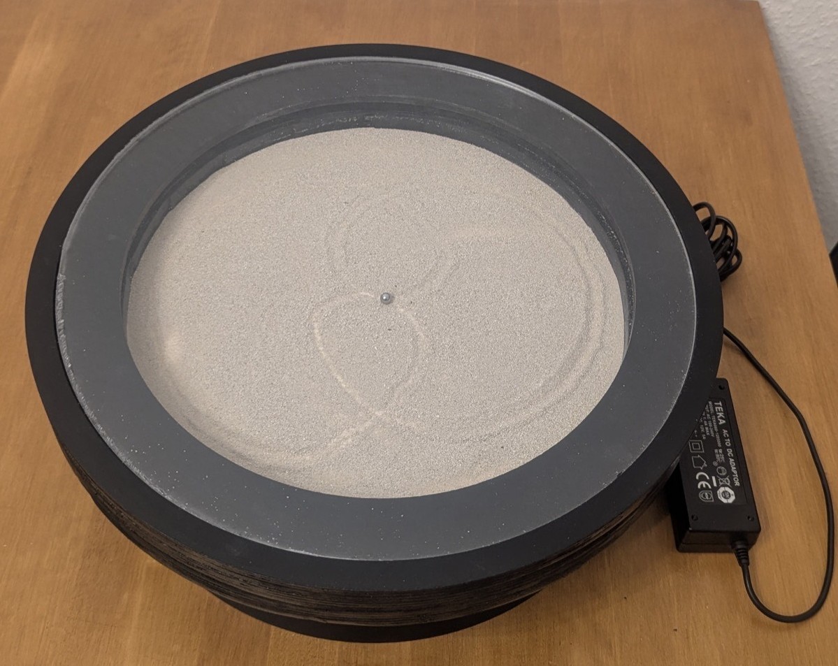
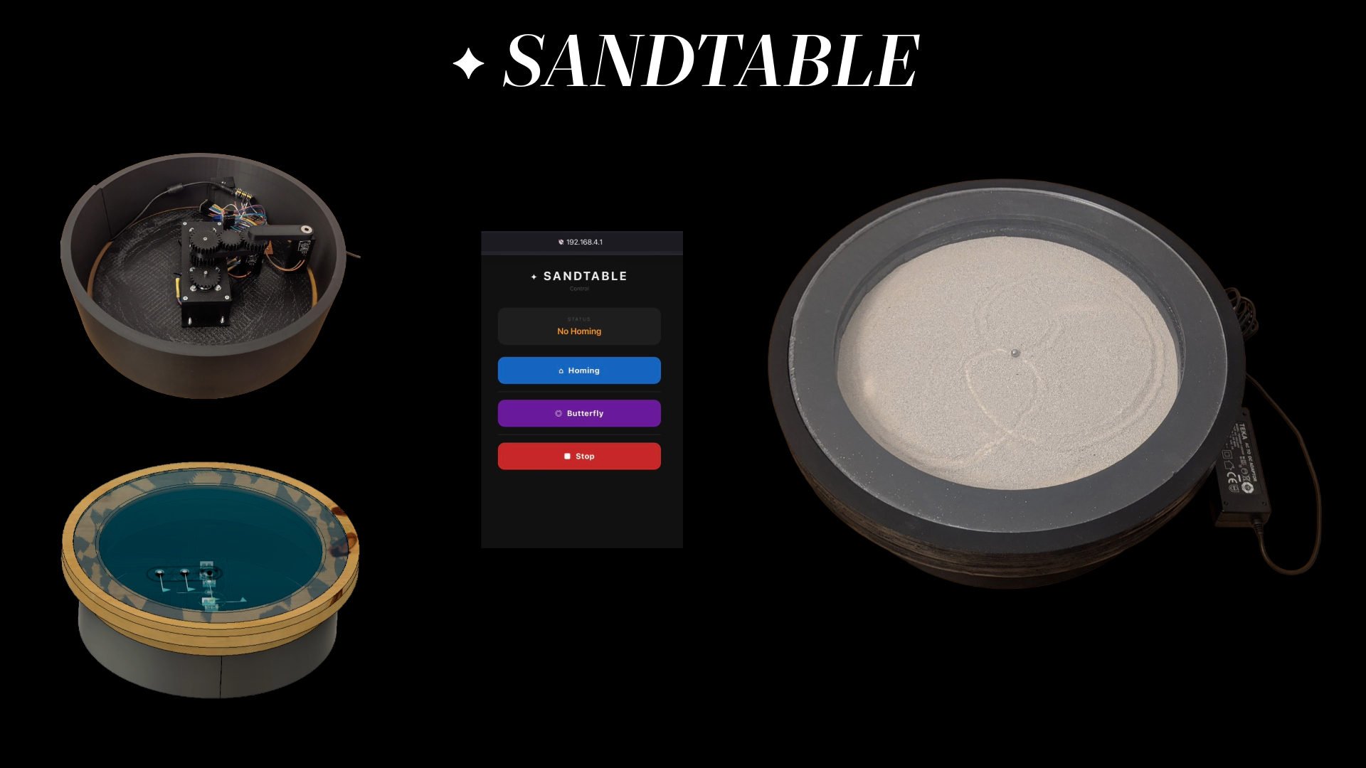
The Sandtable Project
For the Machine Building Week, our group of two (Luzy and I) decided to build a Sandtable - a table in which a steel ball draws patterns in sand, guided by a magnetic arm controlled by a motion system beneath the surface.
Design and Construction
First, we met up at the lab to discuss the concept. We set up a Signal group called "Sandtable" and a shared Fusion 360 workspace to collaborate. After that, Luzy designed the first version of the motion system, while I began designing the outer construction of the table.
Motion System Design
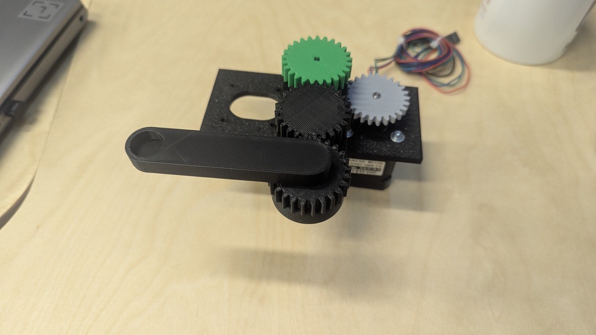
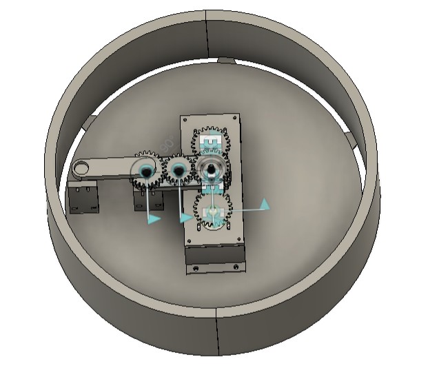
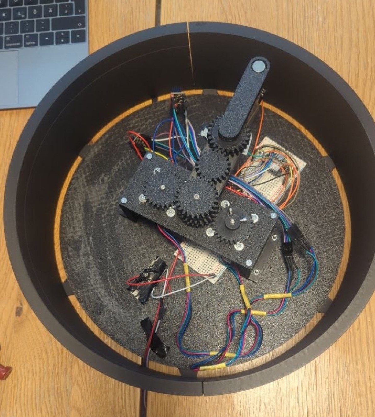
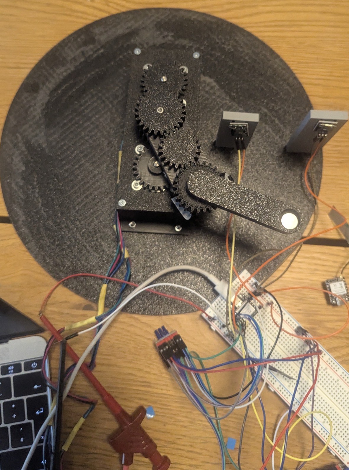
Here you can see the motion system with the bottom plate, reed towers and frame of the construction.
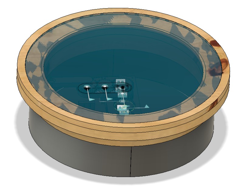
And here's the digital twin of our construction.
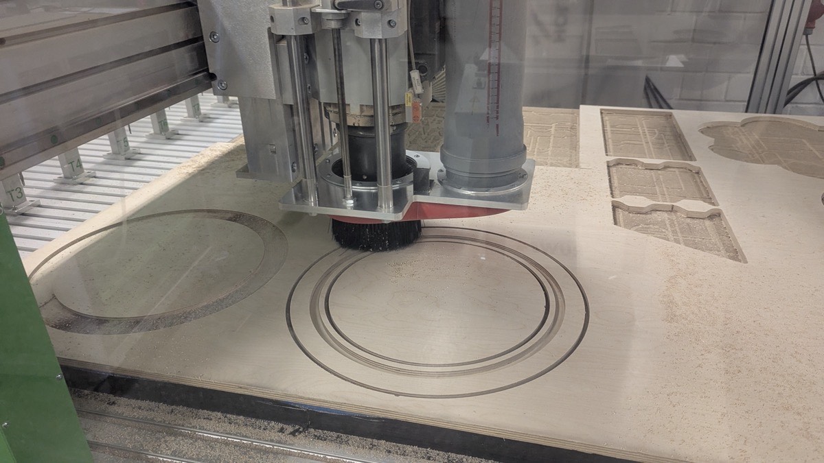
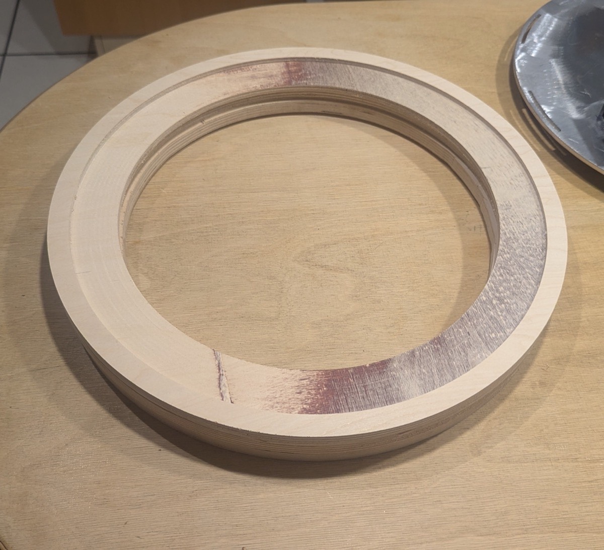
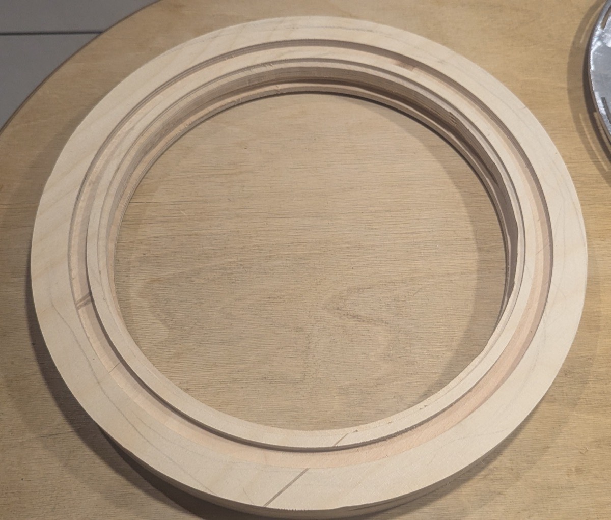
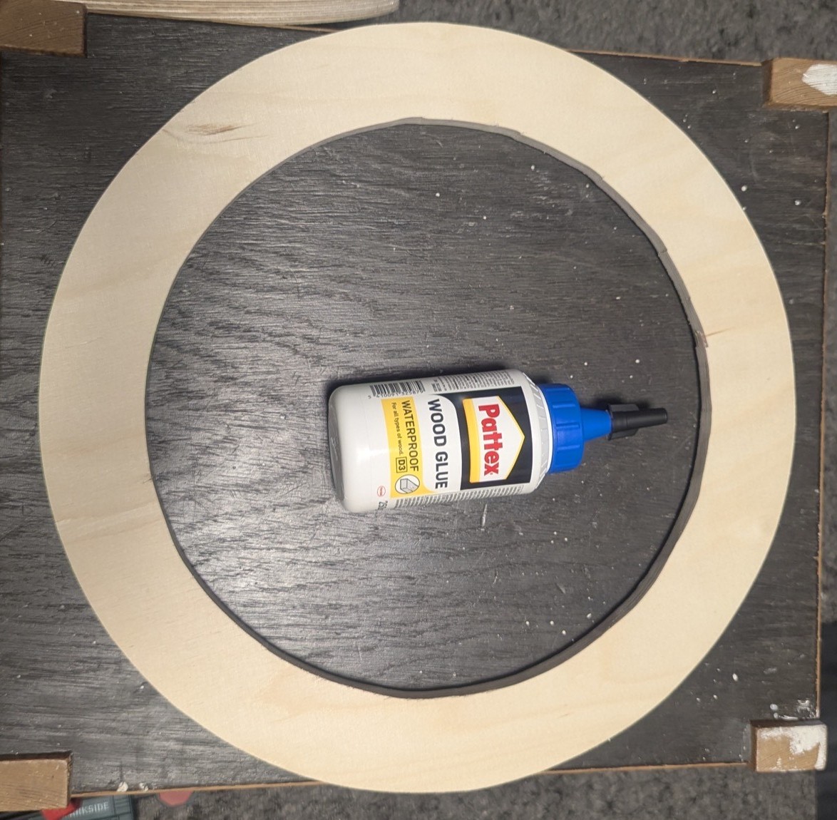
CNC
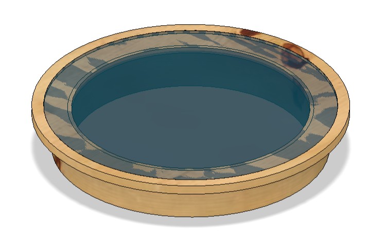
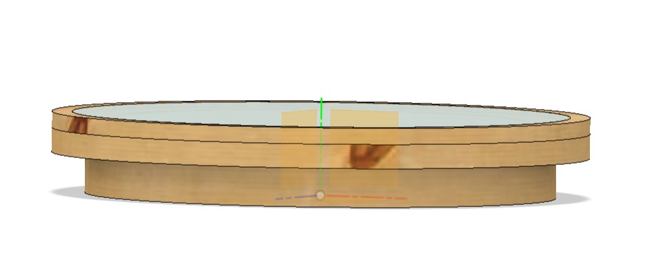
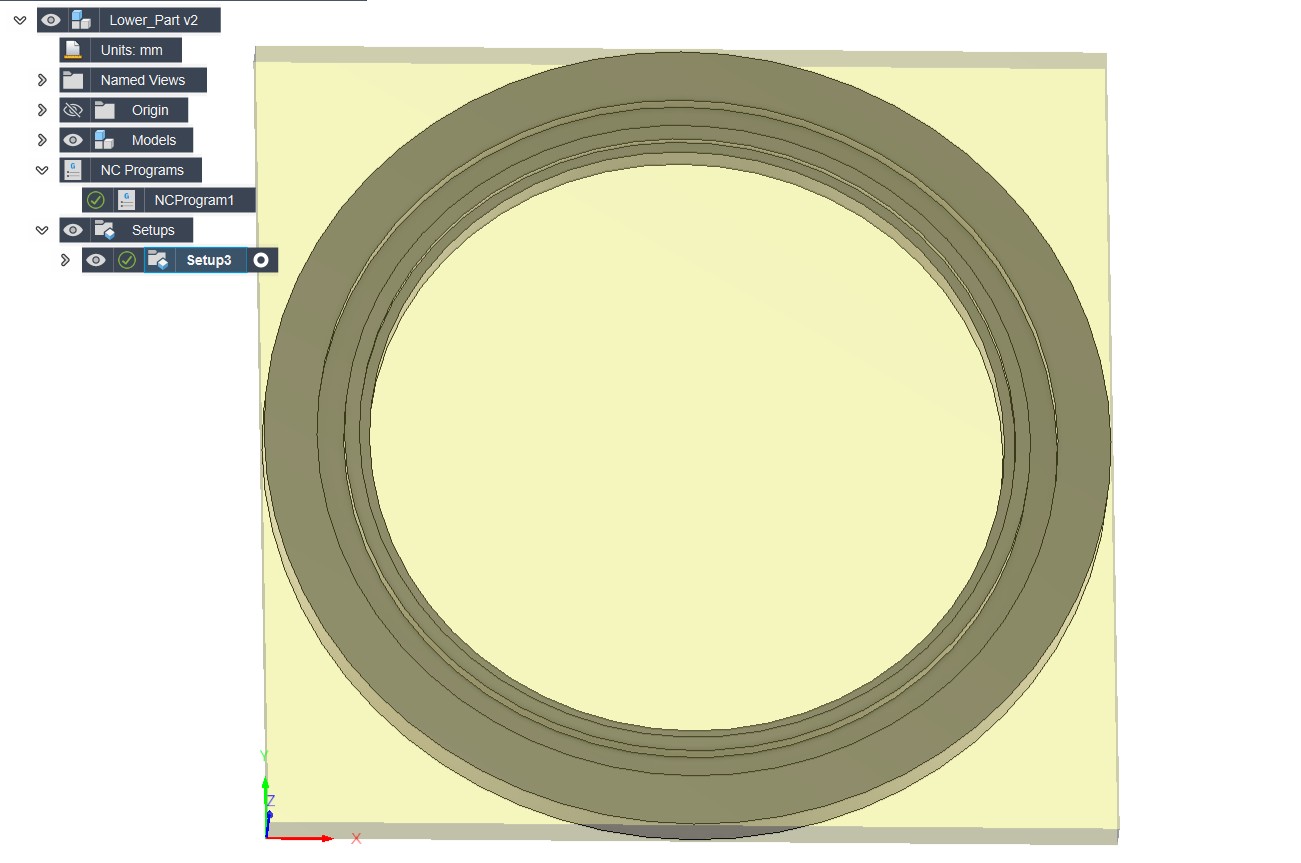
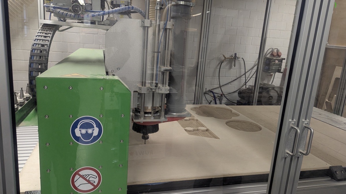
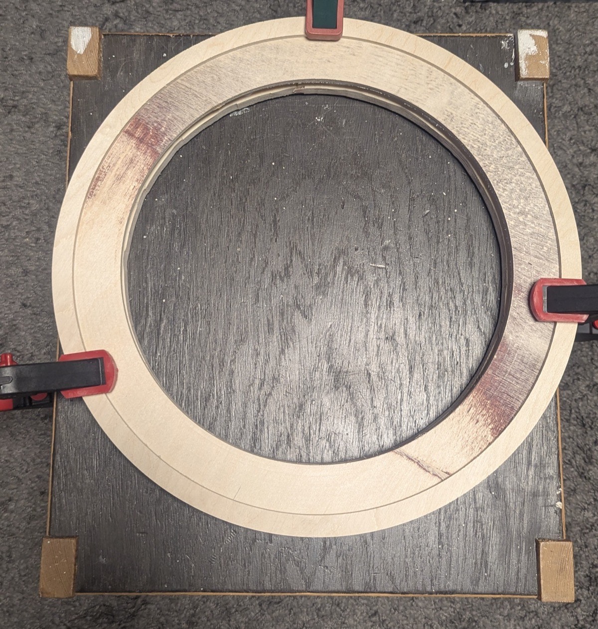
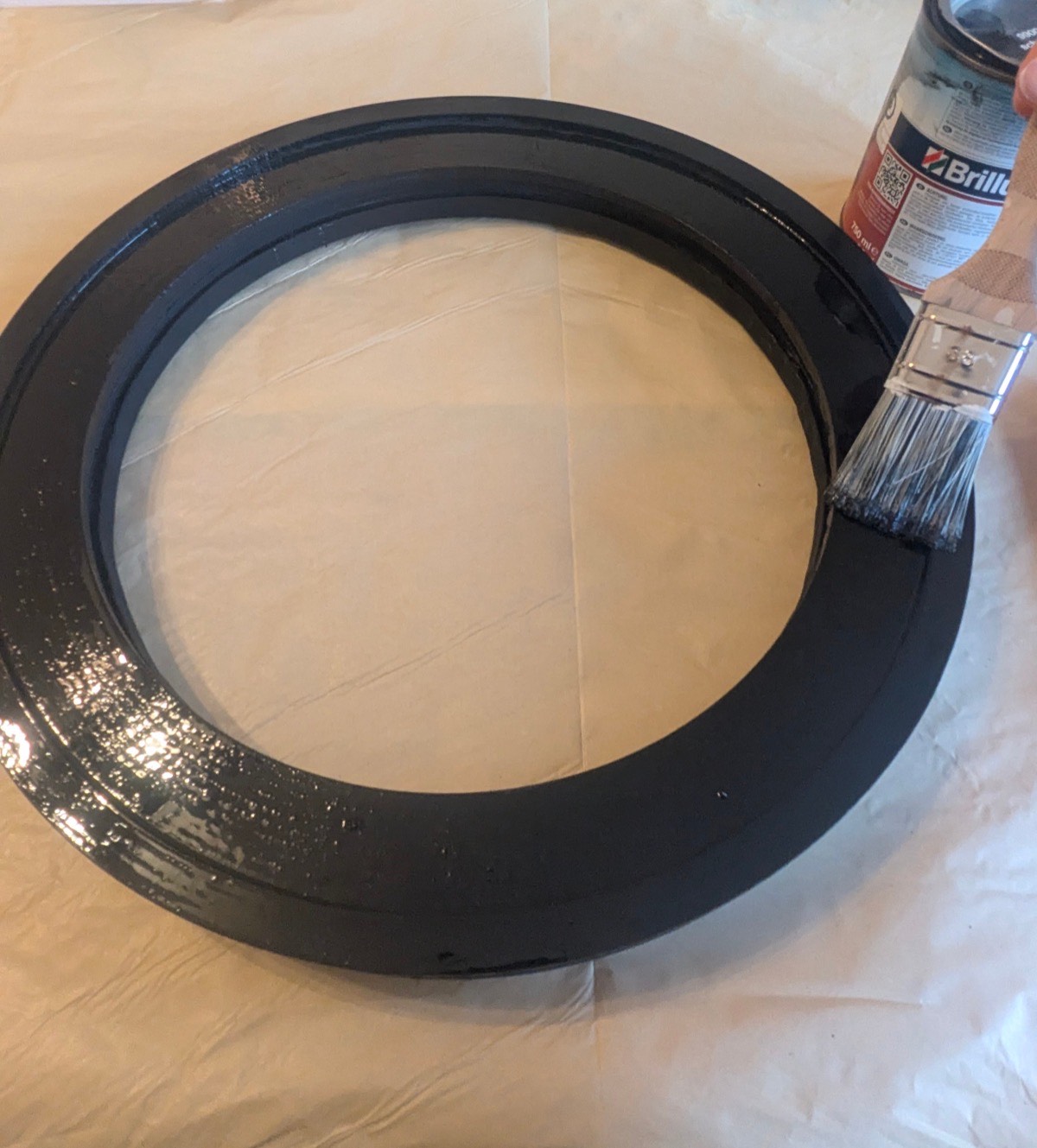
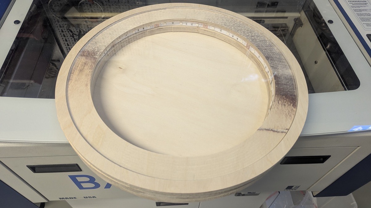
For the top of the construction I designed a wooden table consisting of several rings that are stacked and glued on top of each other to achieve the required height. The design includes a recess on the top surface to fit the acrylic disc, and a matching recess on the underside that sits on top of the frame. After cutting, I tested whether the laser-cut acrylic disc fit into the recess correctly, then glued all parts together.
Design in Fusion 360
Process
Laser Cutting
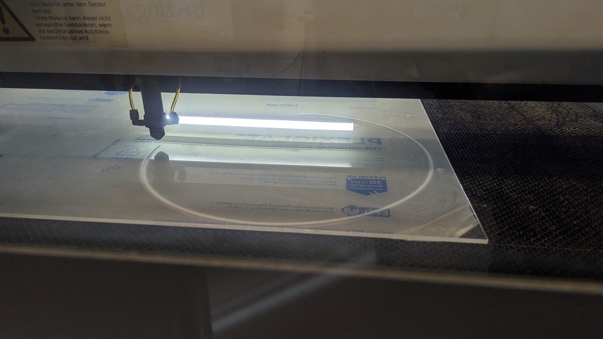
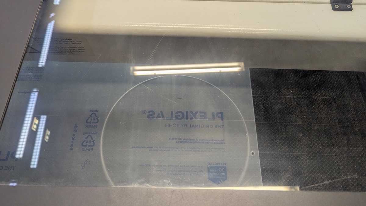
Using the laser cutter, I cut an acrylic disc that serves as the top cover of the Sandtable.
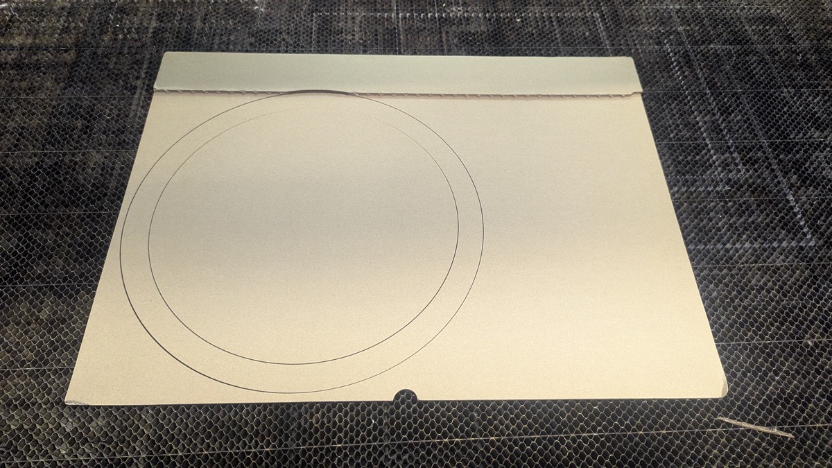
Initially, we planned to build the outer frame from flexible wood produced on the CNC mill. To test whether the material could bend to the required diameter, I first laser-cut a cardboard piece as a template. Unfortunately, the flexible wood broke during the CNC process, so we switched to a 3D printed frame construction instead.
For the bottom plate - the surface on which the sand rests - I laser-cut a circle from thin plywood matching the required diameter. Since it was a simple circular shape, the design and cutting process was straightforward.
3D Printing
Frame For the outer frame I designed two semicircles with snap-fit connectors on the lower end that lock into the base plate, keeping the construction stable during operation.
Base Plate
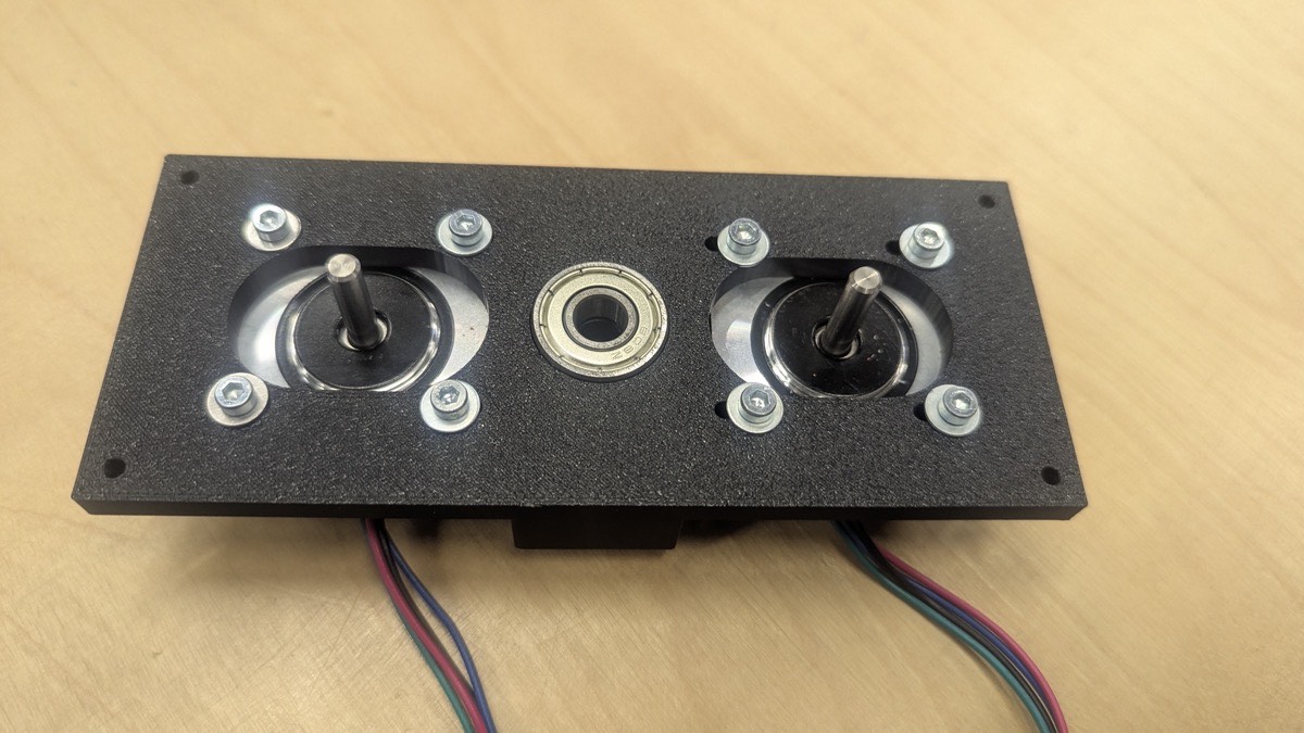
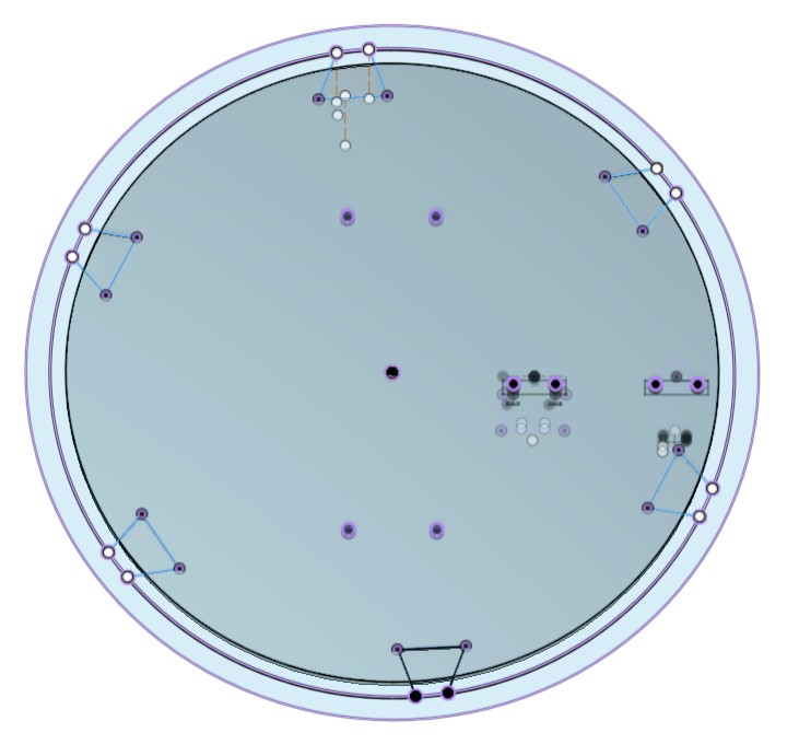
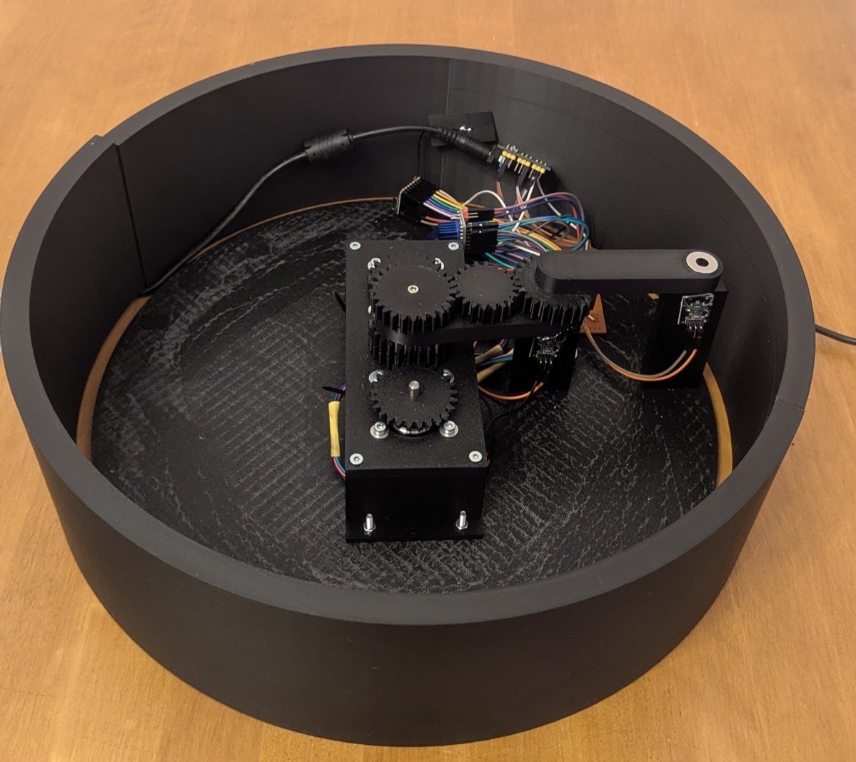
I designed a base plate with mounting holes for the motion system and the reed towers required for homing. On the underside, it features recesses into which the 3D printed frame snaps, preventing the construction from shifting when the arm is in motion.

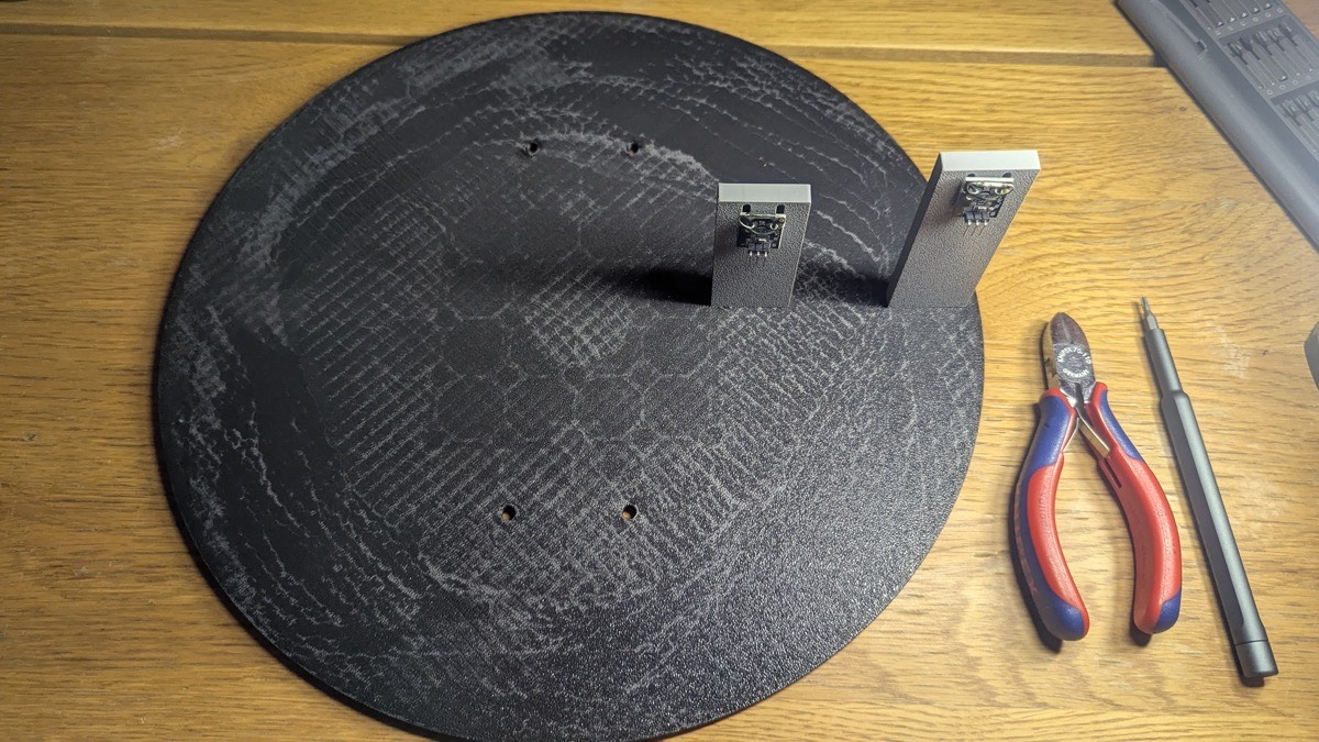
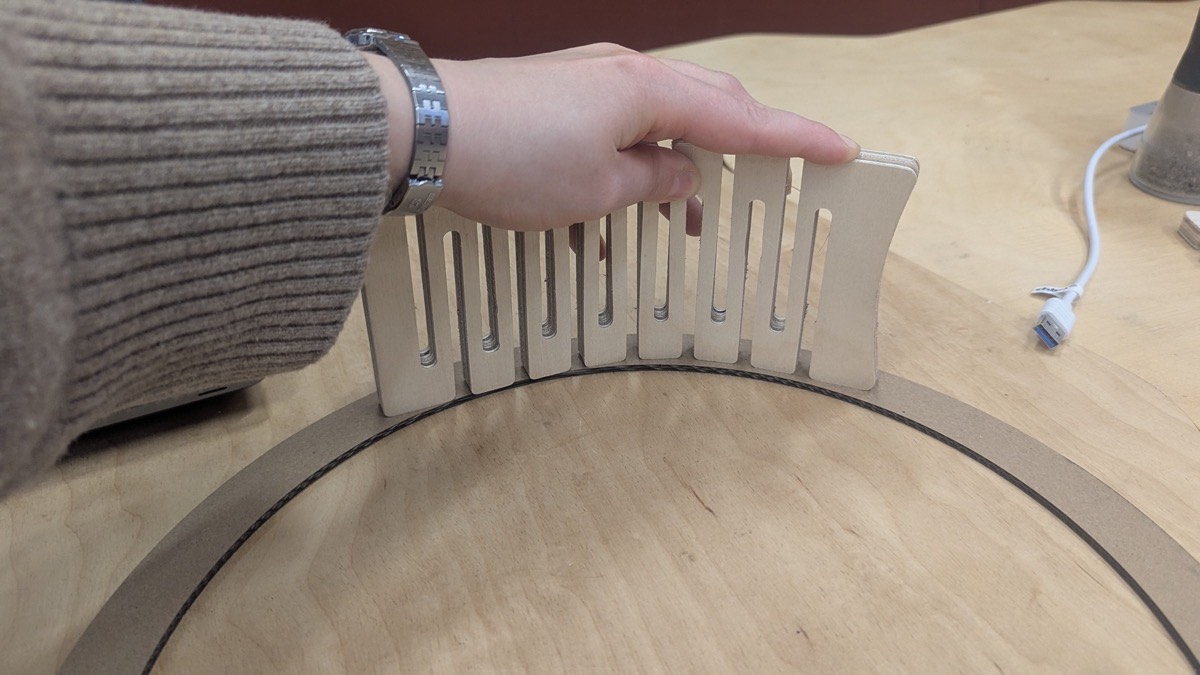
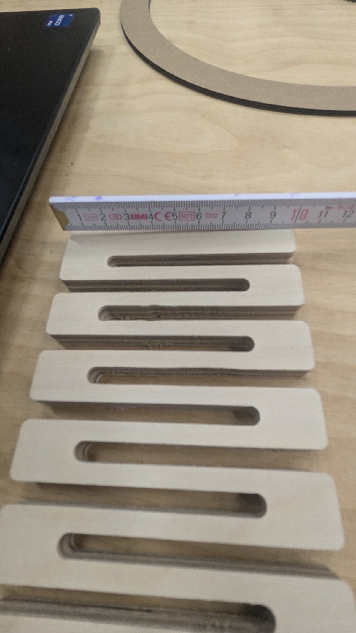
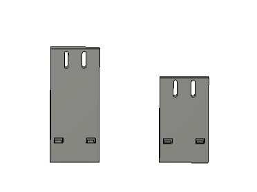
Reed Towers The reed towers are two small rectangular blocks, each with two slots on top for adjusting the height of the reed sensors, and two holes on the bottom for screws that are secured with nuts on the sides.
Electronics
Components
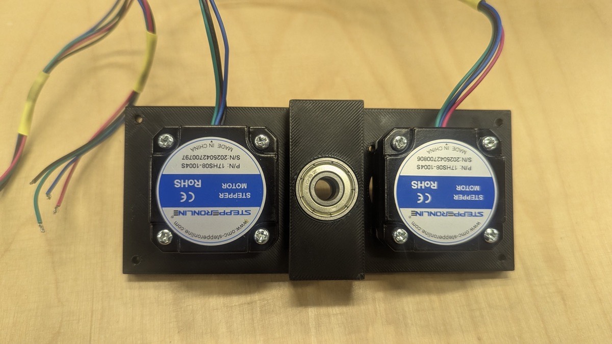
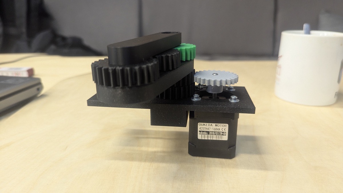
- 2x Stepper Motors - Drive the two arms of the motion system, each controlling one axis of movement.
- 2x Reed Switches - Magnetic sensors used as end stops for the homing routine. They close the circuit when the magnet on the arm reaches the correct home position.
- XIAO ESP32 S3 - The microcontroller, responsible for running the motion control firmware and hosting the web-based control interface as a Wi-Fi access point.
- 2x TMC2209 Stepper Driver - Control the stepper motors with smooth, quiet operation and allow current adjustment via UART.
- Power Supply - Provides the required voltage (12V) for the stepper motors and drivers.
- Logic Level Shifter (12V / 5V / 3.3V) - Converts signal voltages between the different components, since the ESP32 operates at 3.3V while other parts require 5V or 12V.
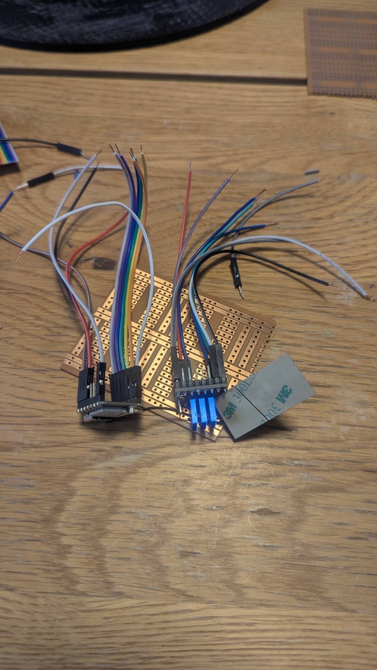
- Perforated Circuit Board (Perfboard) - Used to permanently connect all components after the breadboard testing phase.
- Ball Bearings - Ensure smooth and low-friction rotation of the motion system arms.
Wiring and PCB
Step 1 - Breadboard Testing First, I assembled all components on a breadboard and tested whether the motors moved correctly. I then wrote an initial program in the Arduino IDE to home both segments of the motion system. For homing, magnets are attached to the ends of each arm - when an arm reaches its home position, the magnet closes the corresponding reed switch, signaling the correct position.
Step 2 - PCB Sketch After verifying that the motion system and homing process worked correctly, I drew a wiring sketch for the perfboard to avoid any mistakes during soldering.
Step 3 - Soldering I prepared all cables and soldered them onto the board according to the previously made sketch.
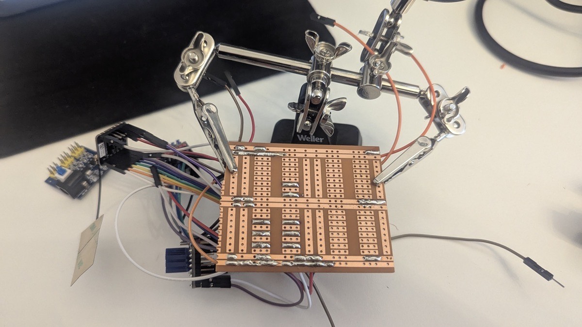
After finishing the board, I was naturally a little nervous about potential wiring mistakes - but testing showed that everything worked just as well as on the breadboard.
Mounting the Components
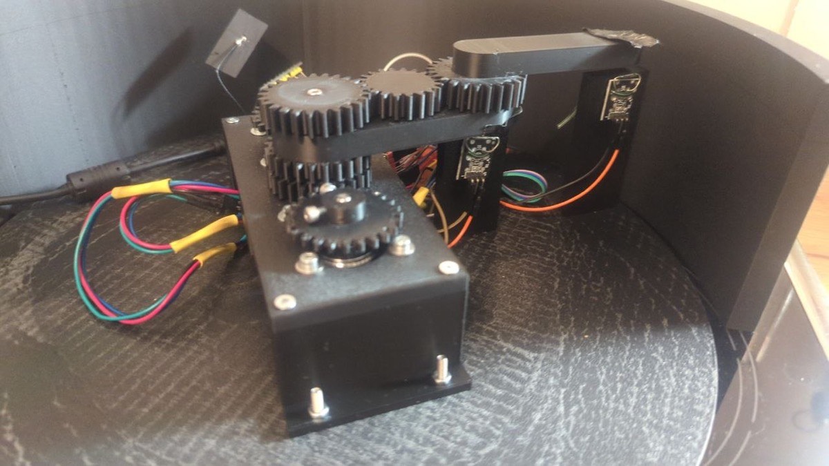
When mounting all components for final assembly, I noticed that the arm was a few millimeters too tall once the lid was placed on top. I therefore adjusted the height of both the reed towers and the motor mount before completing the final assembly.
Software and Control
Homing
As mentioned above, I first programmed the homing routine, which moves both arms to their starting positions using the reed switches as end stops.
The homing routine is implemented using the AccelStepper library. When triggered, both motors run at a fixed speed in the negative direction simultaneously. Each motor continuously checks its corresponding reed switch - as soon as a switch is pulled LOW, the motor stops and its current position is set to zero. Once both motors have reached their home position, the program verifies that both reed switches are still closed. If the verification fails, the homing routine restarts automatically. On success, the internal step counters are reset and the machine is ready for use.
void doHoming() {
  modus    = HOMING;
  homingOK = false;
  stopFlag = false;

  digitalWrite(M1_EN, LOW);
  digitalWrite(M2_EN, LOW);
  delay(100);

  motor1.setSpeed(-HOMING_SPEED);
  motor2.setSpeed(-HOMING_SPEED);

  bool m1 = false, m2 = false;

  while (!(m1 && m2)) {
    server.handleClient();

    if (!m1) {
      if (digitalRead(REED1) == LOW) {
        motor1.setSpeed(0);
        motor1.setCurrentPosition(0);
        m1 = true;
      } else {
        motor1.runSpeed();
      }
    }
    if (!m2) {
      if (digitalRead(REED2) == LOW) {
        motor2.setSpeed(0);
        motor2.setCurrentPosition(0);
        m2 = true;
      } else {
        motor2.runSpeed();
      }
    }
  }

  delay(300);

  if (digitalRead(REED1) == LOW && digitalRead(REED2) == LOW) {
    homingOK      = true;
    m1StepCounter = 0;
    m2Position    = 0;
  } else {
    delay(1000);
    doHoming();
    return;
  }

  modus = IDLE;
}
Web Application
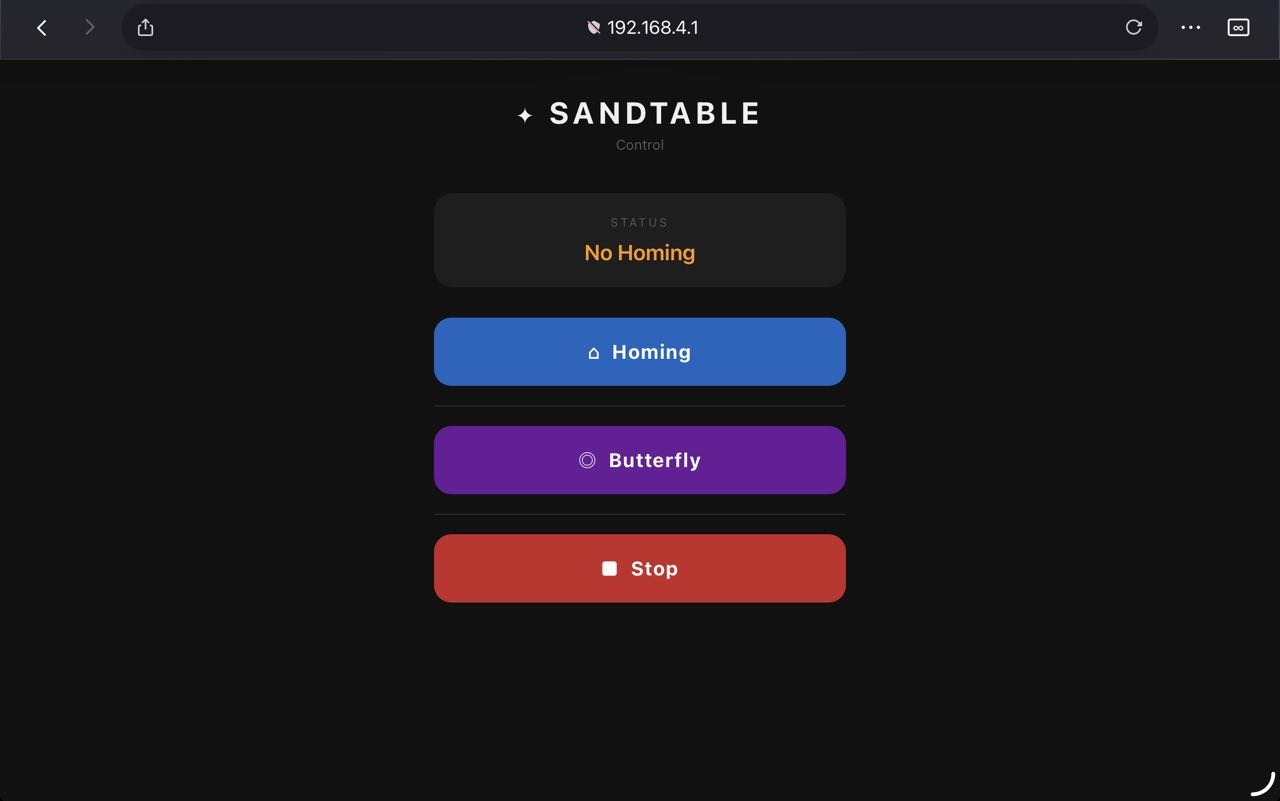
The firmware sets up the ESP32 as a Wi-Fi access point with the SSID "Sandtable", reachable at the fixed IP address 192.168.4.1. The web interface is served directly from the ESP32's flash memory. It displays the current machine status and offers three controls: a Homing button to run the homing routine, a Spiral button to start drawing, and a Stop button to halt the machine at any time. The status display updates automatically every 1.5 seconds. The spiral button is locked until homing has been completed successfully - if triggered beforehand, the interface returns an error message.
// Access Point
WiFi.softAP(AP_SSID, AP_PASS);

// Command handler
server.on("/cmd", []() {
  String a = server.arg("a");

  if (a == "homing") {
    server.send(200, "text/plain", "Homing is running...");
    doHoming();
  }
  else if (a == "spirale") {
    if (!homingOK) {
      server.send(200, "text/plain", "Error: Run homing program first!");
      return;
    }
    modus    = BUTTERFLY;
    stopFlag = false;
    server.send(200, "text/plain", "Drawing ...");
  }
  else if (a == "stop") {
    stopFlag = true;
    motor1.setSpeed(0);
    motor2.setSpeed(0);
    modus = IDLE;
    server.send(200, "text/plain", "stopped");
  }
});
The this program is producing an image that looks a little bit like a butterfly in the sand.
void butterflyStep() {
  if (stopFlag || m2Position >= MAX_RADIUS) {
    motor1.setSpeed(0);
    motor2.setSpeed(0);
    digitalWrite(M1_EN, HIGH);
    digitalWrite(M2_EN, HIGH);
    mode     = IDLE;
    stopFlag = false;
    Serial.println("[Butterfly] Finished");
    return;
  }
  motor1.setSpeed(M1_SPEED);
  motor1.runSpeed();
  m1StepCounter++;
  if (m1StepCounter % STEPS_PER_REV == 0) {
    motor2.move(RADIUS_PER_REV);
    m2Position += RADIUS_PER_REV;
  }
  motor2.setSpeed(M2_SPEED);
  motor2.run();
}
Here's a screenshot of the webside that is hosted on the ESP32 to control the sandtable.
Reflection
Overall, the project went well and we were able to build a fully functional Sandtable within the given time. Looking back, there are a few things I would approach differently in a future iteration. The base plate design could be improved, as it is currently quite difficult to find the exact angle needed for the frame to snap in correctly during assembly. I would redesign it to make the assembly process more intuitive. Additionally, I used crushed sand, which created too much friction for the ball to roll smoothly. For continued use, I would replace it with polished quartz sand to allow for cleaner and more precise patterns. The next steps for the project will be on Luzy's side - she plans to write a program that supports a variety of different patterns, and potentially allows users to import images that the Sandtable can then draw autonomously.
Download
Presentation Slide and Video
Presentation Slide