Water quality measurement buoy
🌊🐳🌡🚣
What are we talking about??
Water quality is an essential factor for the health and well-being of people and ecosystems. However, many coastal and lake areas suffer from pollution from various sources, such as industrial, agricultural, urban or tourist activities. This situation negatively affects biodiversity, food security, economic development and the quality of life of local communities. To address this problem, continuous and efficient monitoring of water quality is required, which makes it possible to detect and prevent environmental and health risks, as well as measures to design and implement appropriate management and restoration. However, conventional monitoring methods, based on specific sampling and laboratory analysis, are expensive, slow and limited in their spatial and temporal coverage. In this context, smart buoys emerge as a technological innovation that offers a more effective and sustainable solution for monitoring water quality. These buoys are equipped with a variety of advanced sensors that can measure a wide range of environmental parameters, such as temperature, salinity, pH, dissolved oxygen, turbidity, chlorophyll, nutrients, heavy metals, hydrocarbons, bacteria, viruses, etc. In addition, smart buoys can transmit the collected data in real time via wireless or satellite networks, making it easier to access and process by scientists and environmental authorities. The objective of this project is to build a low-cost smart buoy to measure the water quality of bays and lakes, using accessible and easy-to-assemble materials and components. This buoy will allow obtaining relevant and updated information on the state and evolution of aquatic ecosystems, as well as identifying and alerting about possible pollution episodes. The project is part of a Cuban-Belgian collaboration, financed by the Academy of Research and Higher Education (ARES), which seeks to promote the exchange of knowledge and experiences between both countries in the field of environmental monitoring.
Background

The SmartWater project is a participatory and citizen initiative that seeks to improve the monitoring of water quality in ponds and waterways in the Brussels region, through the use of innovative, low-cost, sustainable and accessible tools for all. The project is led by a consortium of associations, universities and an administration, which collaborate with each other to develop and experiment with different technological solutions, such as autonomous aquatic robots, an interactive application for observing aquatic environments, pedagogical workshops in the field and research projects. scientific investigation. The SmartWater project is a direct antecedent of BBCuba, and inspiration and reference from which I am taking advange for my own project, building a low-cost smart buoy to measure the quality of the water in bays and lakes, using accessible and easy-to-assemble materials and components. . Like SmartWater, this project has a participatory and citizen dimension, as it seeks to involve local communities in the monitoring and conservation of aquatic ecosystems. The SmartWater project therefore offers an example of good practices and lessons learned that I can apply and adapt to my own context.
What is the dream?

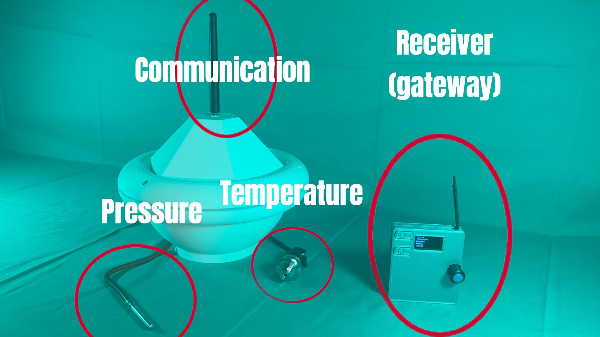
The idea is to create a smart buoy with the maximum possible autonomy, efficiency and independence, capable of measuring water temperature and pressure, parameters necessary for the study of reservoirs, being able to transmit them in “real time” and view them remotely.
System
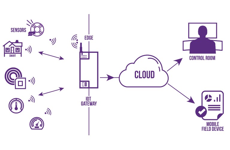
The diagram shows the integration of the different parts of the system, generally a buoy that collects the parameters of temperature and water pressure, sends the data collected via LoRa to a nearby gateway with internet access to be able to access them through a web interface. To develop this system, I tackled 3 basic creation processes:
-> Electronics.
-> Programming.
-> 3D Design.
Electronics
Before thinking precisely about which electronic components to use, microcontroller or design program to use, I must define the functionalities that I need to cover. I need to measure temperature and pressure so the first thing will be to select the sensors. For that we will go back to week 12.
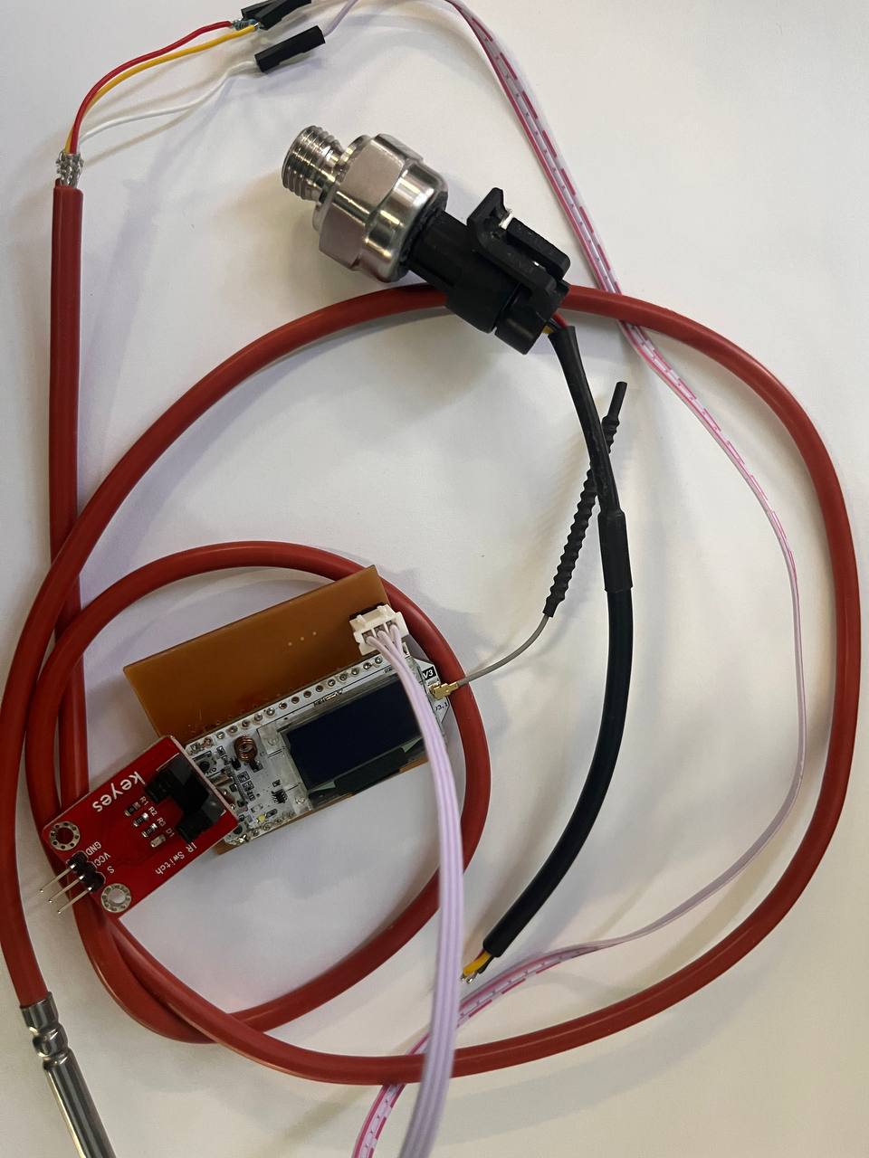
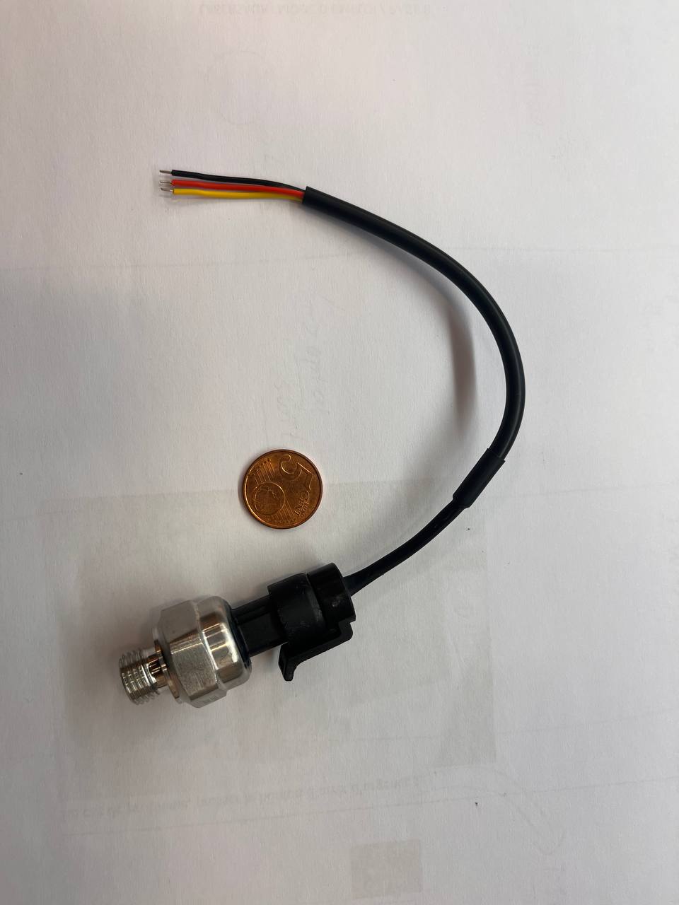
To measure the pressure I will use the HK1100C pressure sensor, it is not ideal but it is cheap and will work for a first version. As explained in week 12, it is an analog sensor, it will give us a voltage value based on the pressure, which I will process to obtain the real pressure value.
Using this example code We check that the sensor is reading correctly, I don't have the equipment to check them but the variation seems reasonable. In any case, we are not looking for much precision in this prototype.
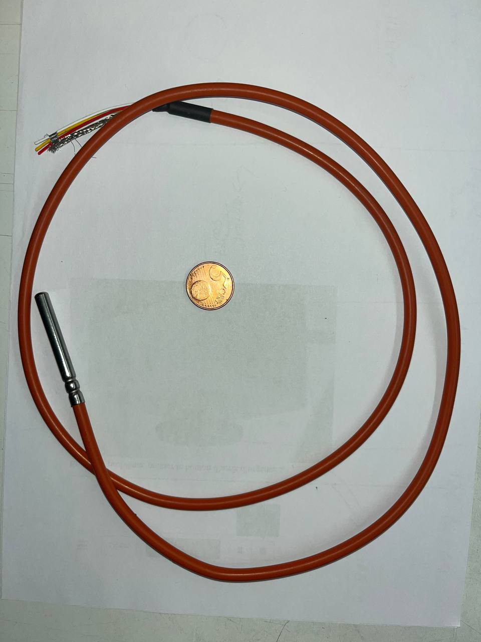
On the other hand, for the temperature sensor I will use the DS18B20, which I also worked on, in week 12. It is a very cheap but quite accurate silicone probe, ideal for immersion, and there is also a lot of literature about it on the Internet. Unlike the HK1100C (the pressure sensor), which is analog, this one has 1-Wire communication, a serial protocol that uses a single data line plus a ground reference for communication.
We will do a reading test on the sensor with this code, to check that we can read it without any problem. We will see that its accuracy compared to the instruments I had in the laboratory is quite good, and its response time is more than acceptable for the purpose.
_V3.png)
Having selected the appropriate sensors, it remains to choose the microcontroller. For several years, in the development of this type of project, LoRa has been used in communication, due to its cost and energy efficiency; so for this first prototype I will use the Heltec V3 board, which integrates an ESP32 with a LoRa in a single device.
This is the diagram showing the integration of the electronic components of the project. As can be seen, there is only one board to connect the sensors to the microcontroller.
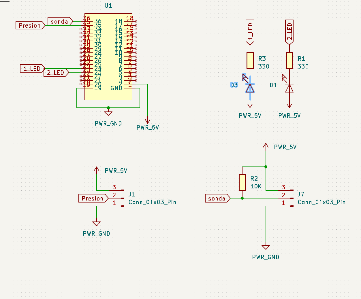
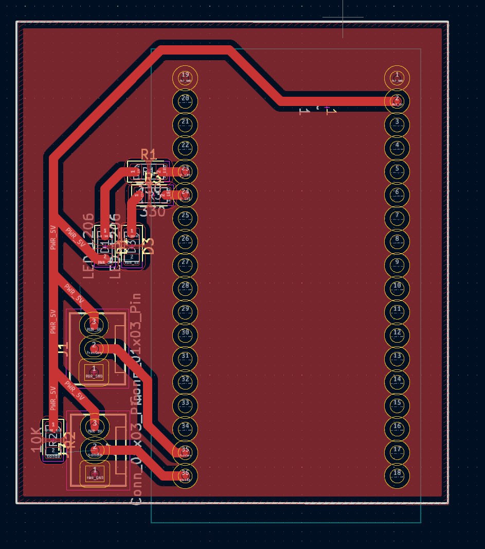
Based on the board from week 12, but making some slight modifications, we have this simple but sufficient PCB for the project.The design is in this link.
With the design ready, I move on to PCB production, as has been done in previous weeks on the FabLab's BANTAN CNC. You can see the process in this quick video.
To power the PCB, I used the input that the Heltec V3 has on the bottom, that way I no longer have to design a regulation stage or add more connectors.
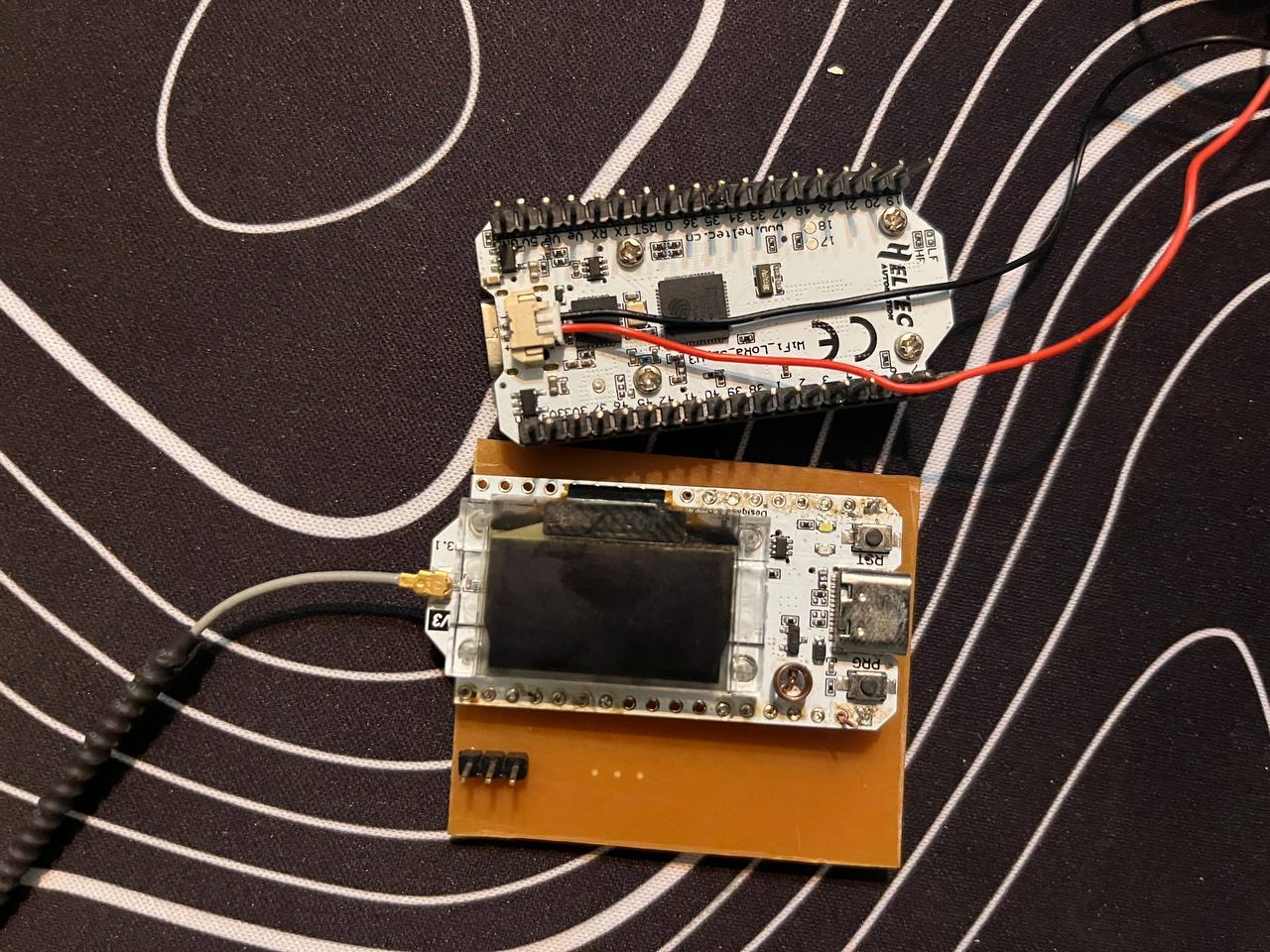
As explained by the manufacturer on its official website, this input is designed to directly connect a 3.7v lithium battery, and even comes prepared to charge it if it is powered by the USB port or, failing that, the VIN.
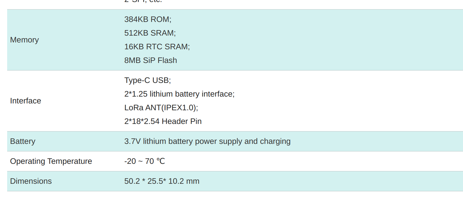
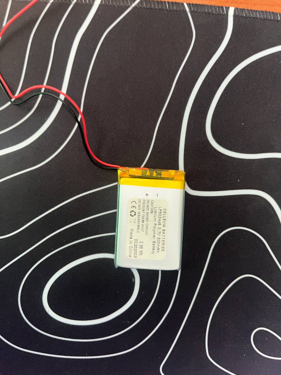
But although there are high-capacity batteries, in the FabLab there were only small batteries, like this 800mA one, and the goal is for the buoy to be in the water for long periods, so it is not enough.
Ideally the system should have 3 moments of energy consumption:
-> Transmission = 120mA.
-> Measurement = 20mA.
-> Deep sleep ~ 0mA.
For the system, due to time and experience issues, I did not implement sleep, but I recognize that it is something very important in the future.
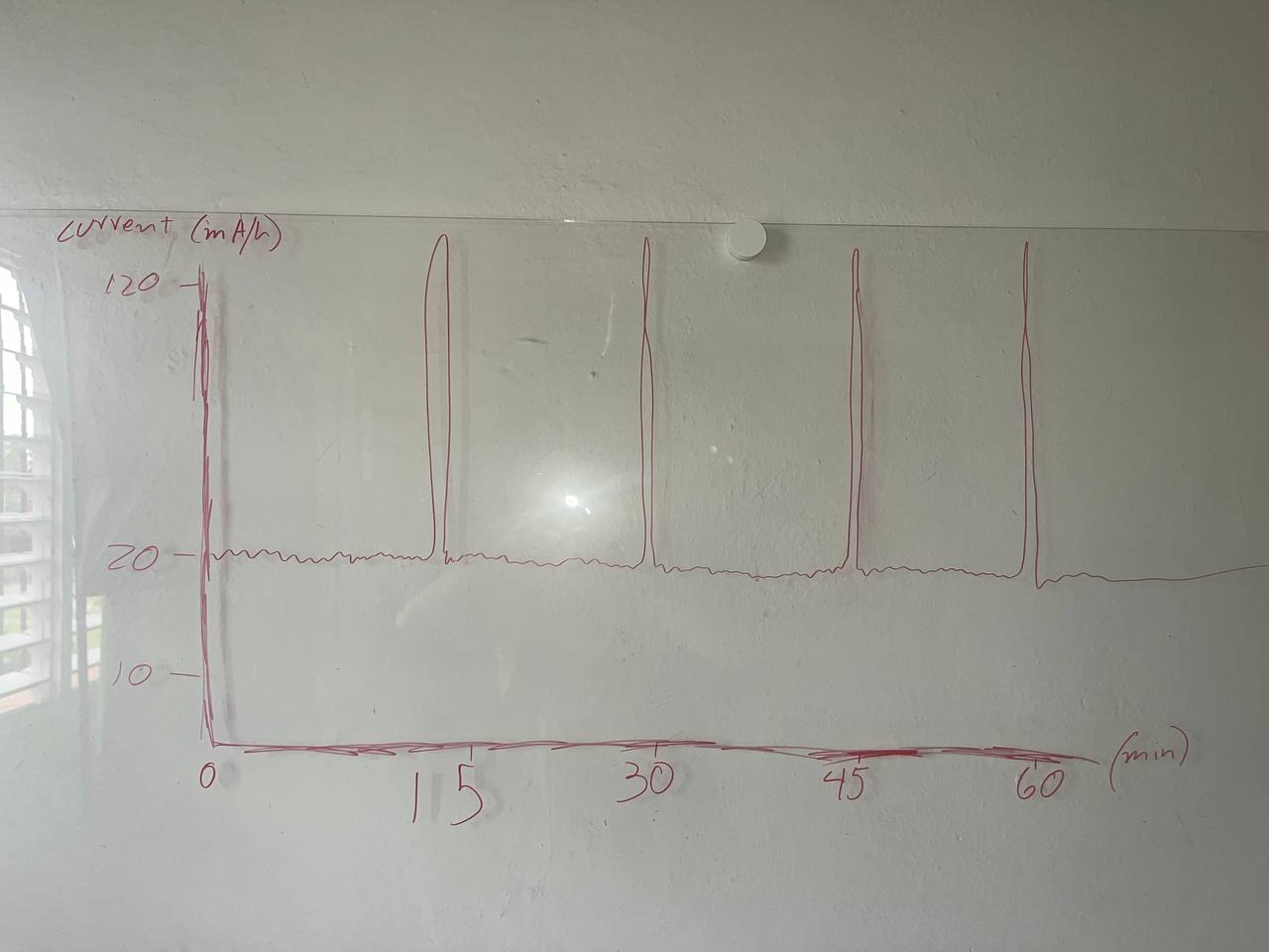
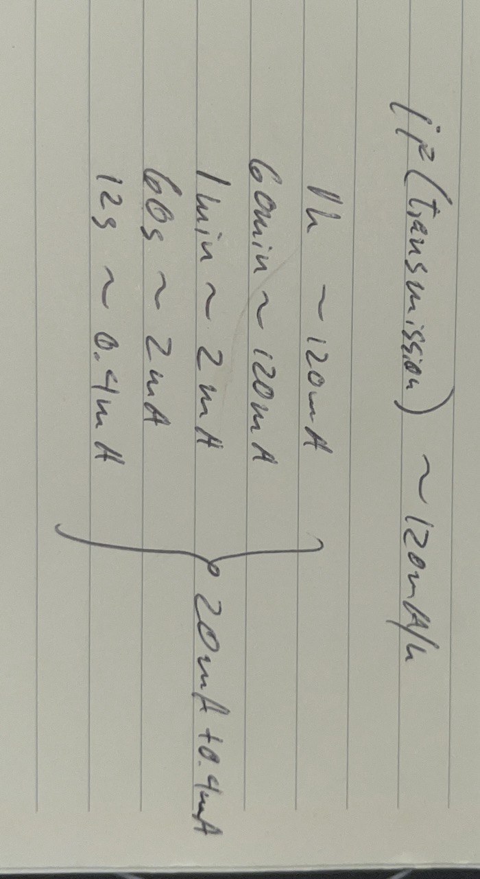
With these clear consumptions, we come to the conclusion that the system will be consuming 20mA every hour, and will have peaks of 120mA every 15 min, for the transmission, being generous we can say that these current peaks last 3s, therefore it would have: that the consumption of one hour is 20mA + the 4 peaks of 120mA, that is, 12s consuming 120mA. In conclusion, the system consumption is 20.4mA.
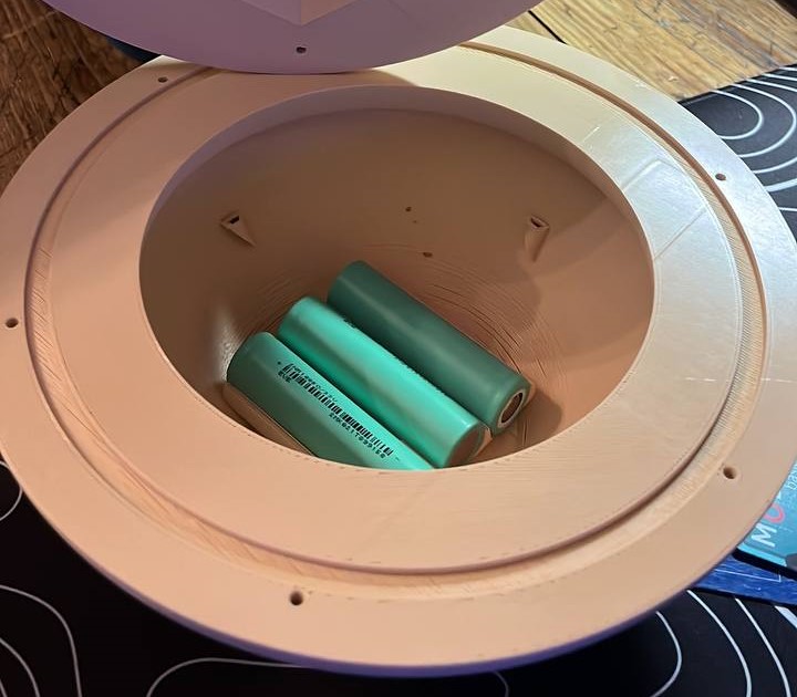
Considering then that the energy demand of the system is almost 500mA per day, I decided to put 3 18650 batteries in parallel, in this specific case they are the 3500mAh capacity battery model, so it should be enough for more than 20 days of continuous use without charging.
As the system is not designed to have 18650 batteries connected, I was not sure how it would behave, to avoid unexpected errors, I used a DC-DC between the battery and the Heltec V3 microcontroller, to always keep the voltage at 3.7v.
.jpeg)
.png)
Finally, with a little silicone, I glued all the electronics to the inside of the plastic body.
Software
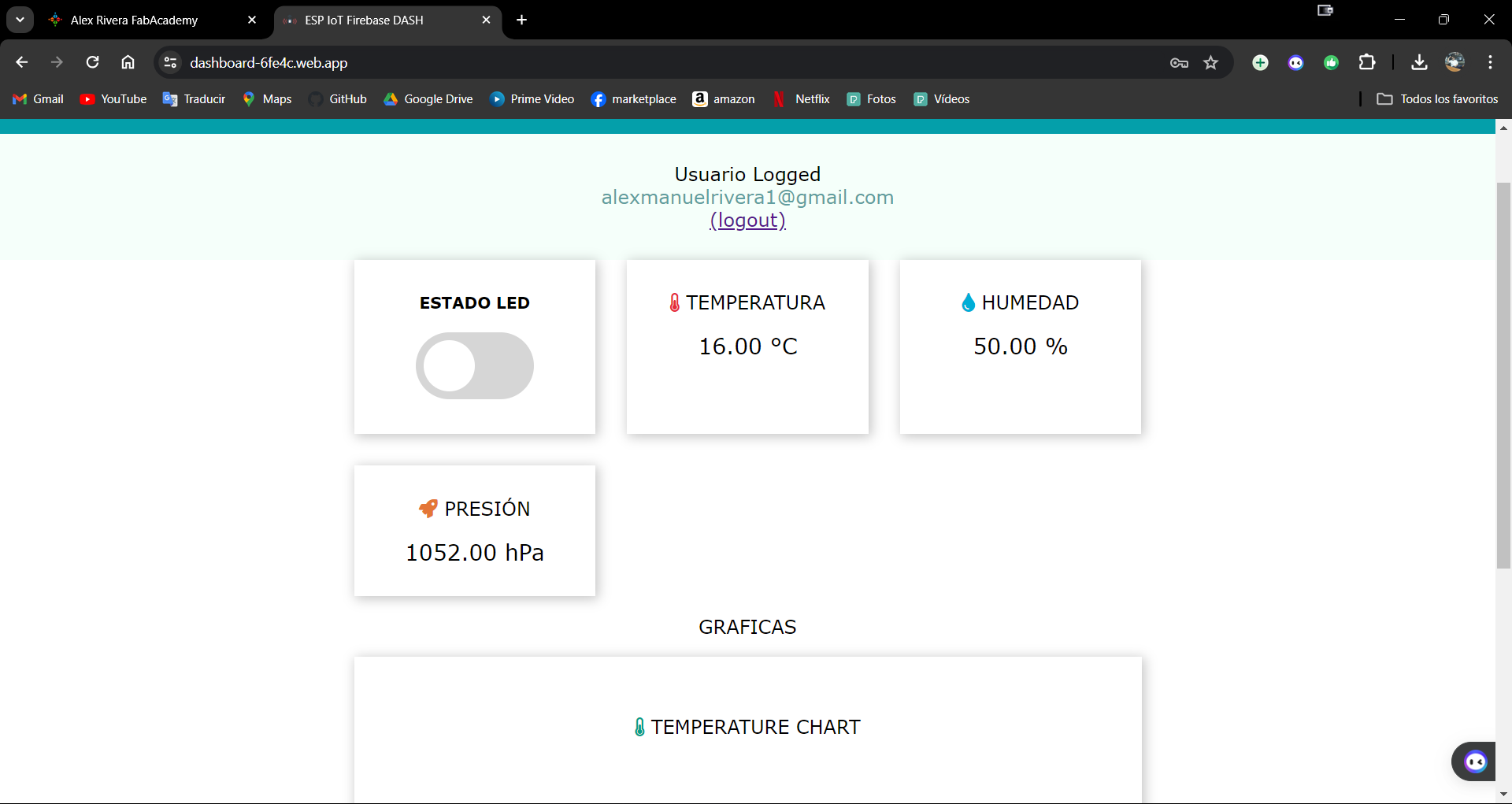
We can now read the sensors without any problem. So, now we can take the data from the sensors and send it to the cloud so that we can view them in this web interface, which appears in the image.
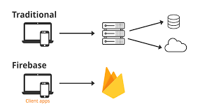
First of all, it is necessary to say that Firebase is a development platform created by Google that facilitates the creation of web and mobile applications. Its main objective is to simplify and accelerate the development process, allowing developers to focus on the quality and functionality of their applications.
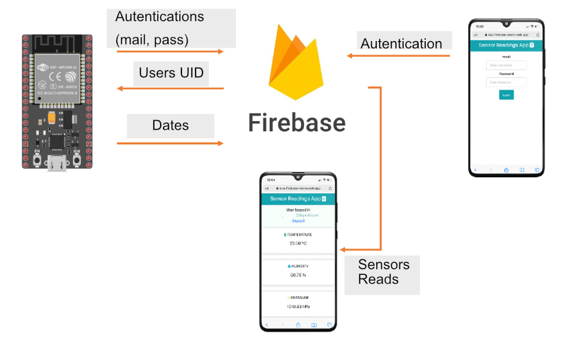
The web application is the same as in week 15, the detailed steps are there, but we will recap them below. The idea is to create a web interface in Firebase to display the sensor readings stored in the database in real time. The sensor readings web page is protected with email and password authentication. The diagram on the left shows the general outline of the project to be implemented.
Once we have searched for “Firebase console” in the browser and created a project, the next step is to install the Firebase CLI, from a terminal inside the project folder:
"npm install -g firebase-tools"
Once completed successfully, now enter the login command:
"firebase login"
And a browser window appears requesting entry to the Gmail account that was used for the Firebase process.
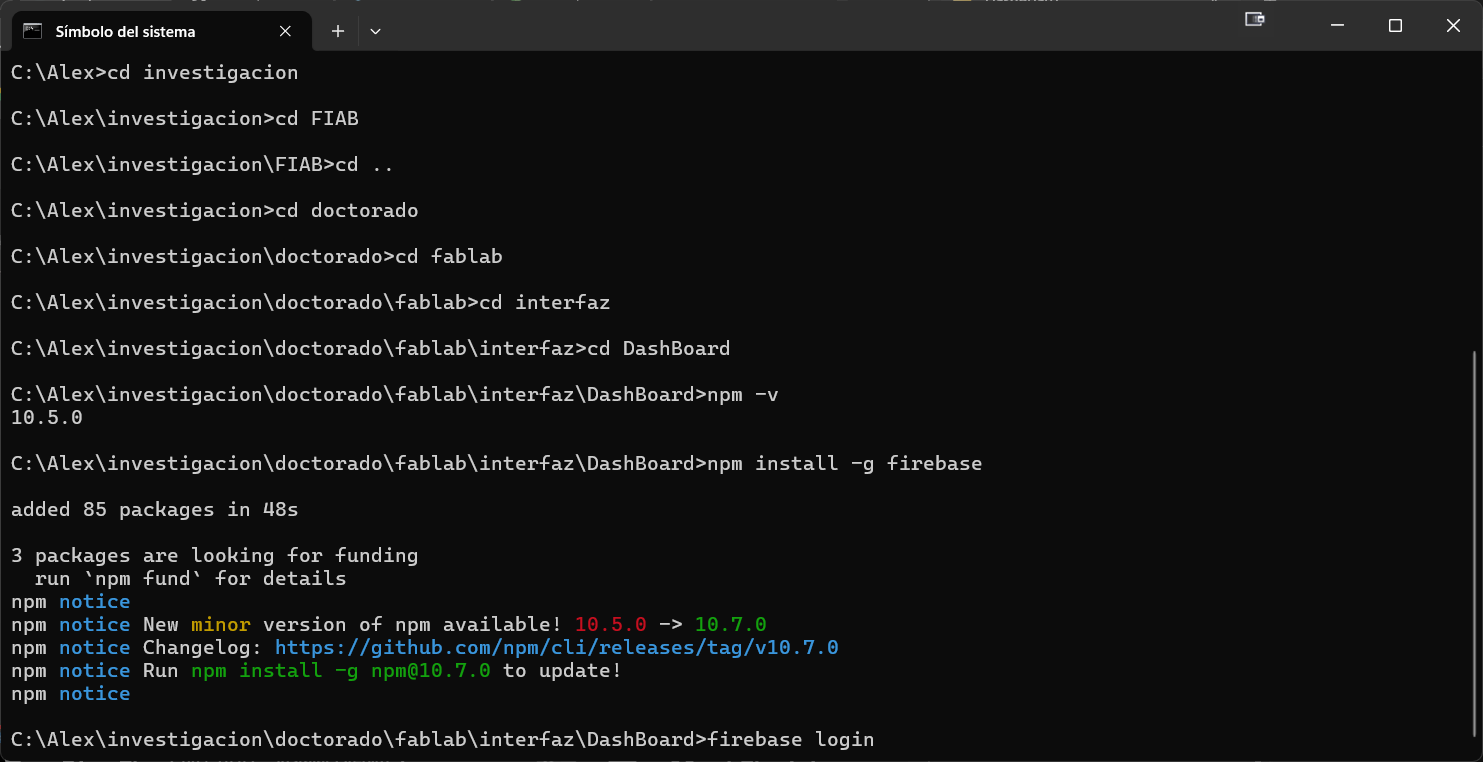
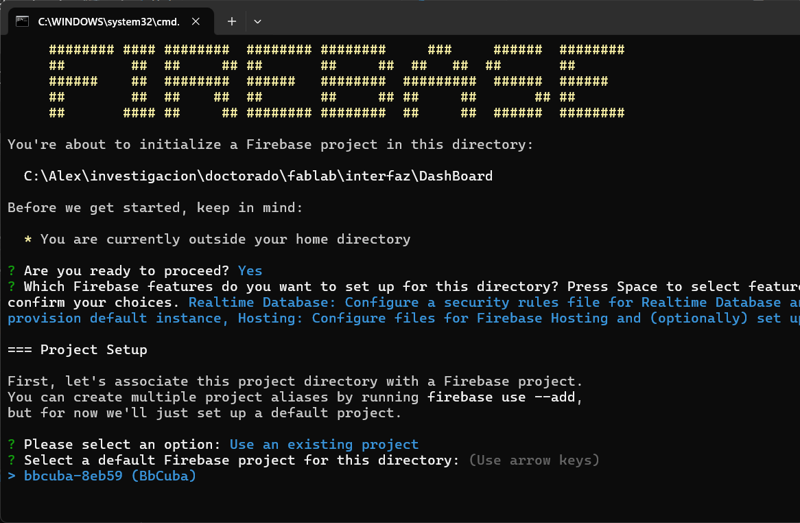
Finally, you need to run the following command: "firebase init" Then the configuration list appears. With the Space Bar we select the option Real-Time Database, Hosting and use an existing project and then press the "ENTER" key.
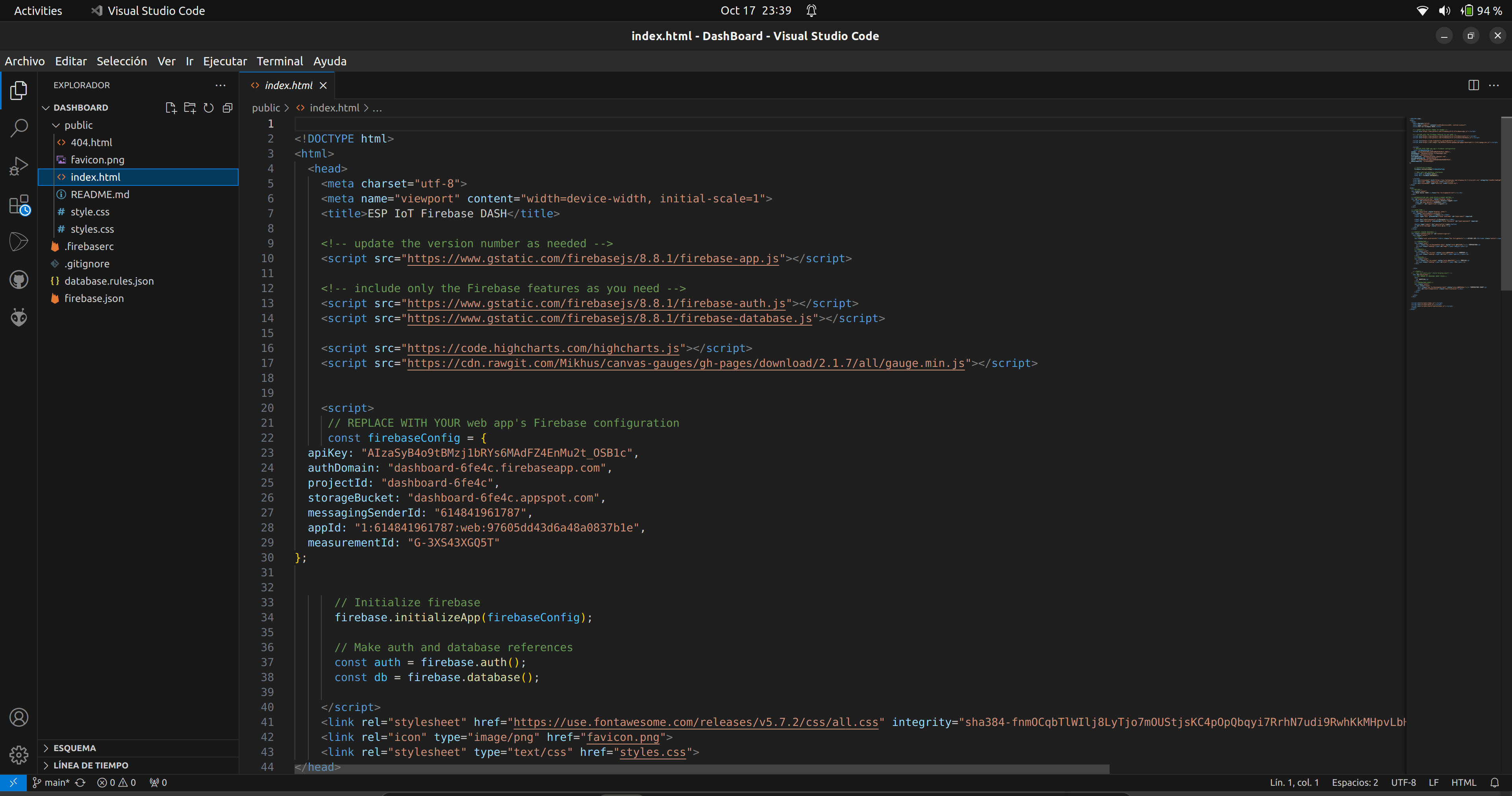
With Firebase installed, it's time to create the WEB. To do this we'll use this code, a fairly clean interface with 3 sensors: temperature, pressure and we'll set humidity, although since we won't be measuring it we'll use a random value for it.
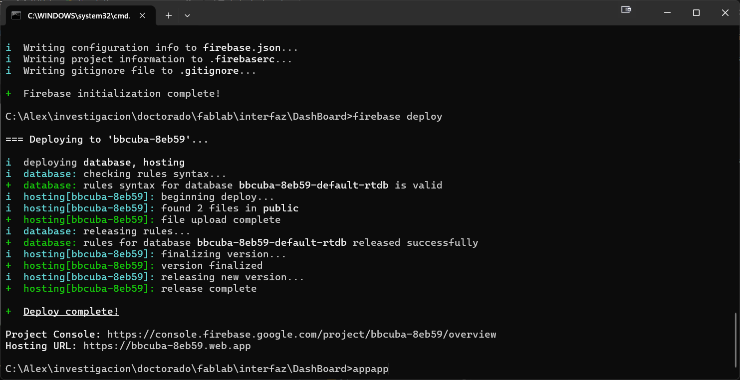
When any file edits are made, we tell Firebase Deployment to upload the files to the hosting. If we upload the files correctly, a link is generated that will take us to the following interface.

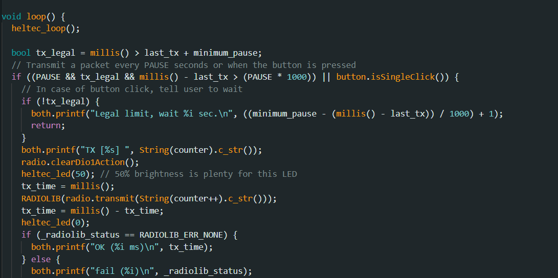
After following these steps, 50% of the programming would be ready, that is, the web interface, but not the programming in the microcontroller. As stated before, the microcontroller selected for the buoy would be the Heltec V3. In general, this microcontroller must read the sensors and send them to the "Gateway" through LoRa, no more, no less.
To achieve this, I will use the communication example from week 14, where I send the Heltec V3 number to another one using LoRa. The change will be that instead of the number, I will send the values read by the sensors.
As a reminder of that week, to program this development board using the Arduino IDE, you have to add the following line in the preferences section:
https://raw.githubusercontent.com/espressif/arduino-esp32/gh-pages/package_esp32_index.json
Then, to be able to quickly use its functionalities, I chose to use the heltec_unofficial library.

Among the main functionalities of this library we find:
1->> heltec _setup() and heltec loop(): To initializes all the necessary library processes in both sections.
2->>radio.transmit(): Transmits the data.
3->>radio.readData(): Receives the data.
4->>both.println(): Shows the Oled screen with format and also the Serial monitor.
Now we need to program the other side, the "Gateway", which will serve as a bridge between the LoRa and the Internet. Although there are commercial models, the truth is that for this stage of the project it is not necessary. Instead, we used another Heltec V3, since it has WiFi, which makes it the ideal bridge.
The function of the gateway, as its name indicates, is to be a link, in this case a link between the received data and the Internet. In general, a second Heltec V3, but this time not as a transmitting buoy but as a gateway, receives the data and since the Heltec V3 has built-in Wi-Fi, we configure it to connect to a Wi-Fi network with Internet access and send the sensor values to Firebase to be displayed.

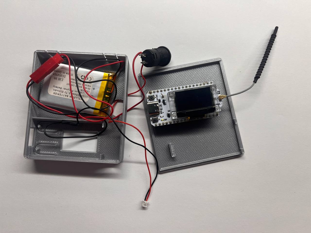
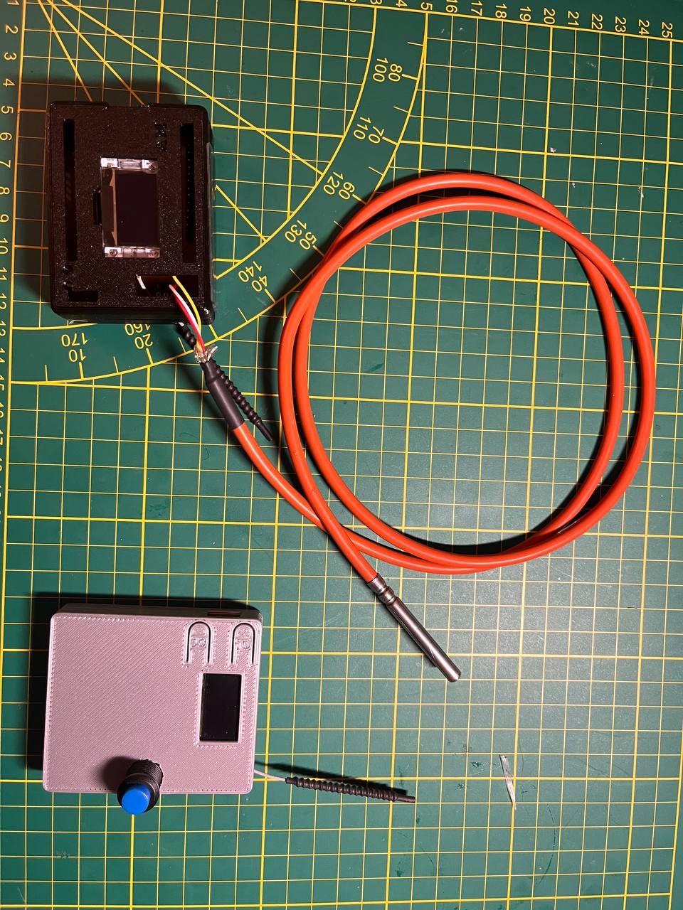
IIn this case, our gateway is just a 3D box with the Heltec V3 and a battery inside, the same 800 mA lithium battery, which I did not use for the buoy but which is perfect for the gateway (which is protected and has access to the electrical network).
Design and manufacturing of the buoy
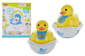
As inspiration I took other designs of similar products on the web, and some classic bathroom elements that from experience we all know float.
Although my imagination told me to do something big and showy that could be seen in the distance and that would serve as a lighthouse for sailors, my reality imposed something else on me...hehe. Well, the size of the design is given by the maximum dimensions of the Prusa printer bed.We can see the step-by-step design process in week 2 and you can download the entire design at this link.
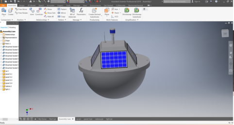
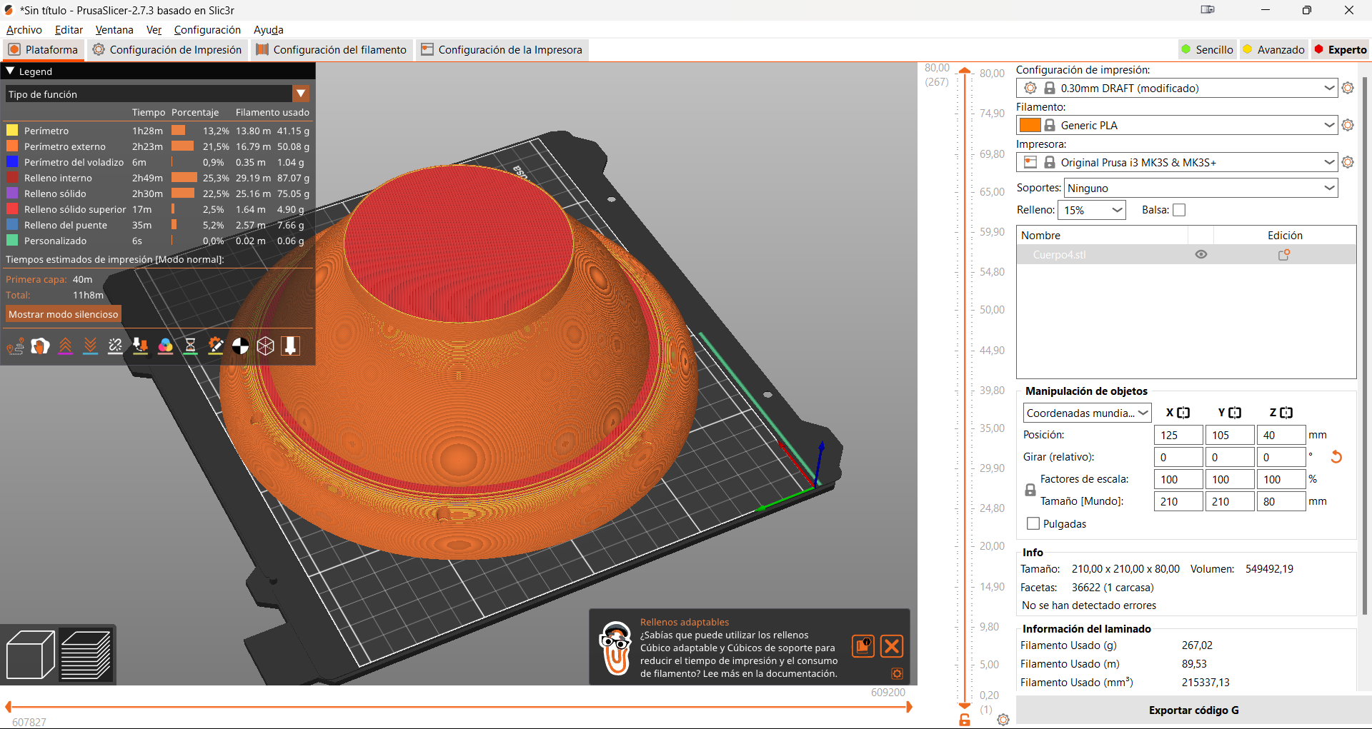
So far all the fabrications have been made with PLA but according to many blogs such as filoalfa3d, this material is not weather resistant, so the final version of this project will be made of Polypropylene, which is a filament apparently designed for this type of applications. Of course, to make all these 3D pieces, the knowledge acquired during the 3D printing week was used.
The design is intentionally made with the fewest possible parts, even so to seal both parts I used a gasket that I casted myself using the knowledge of the Molding and Casting week.
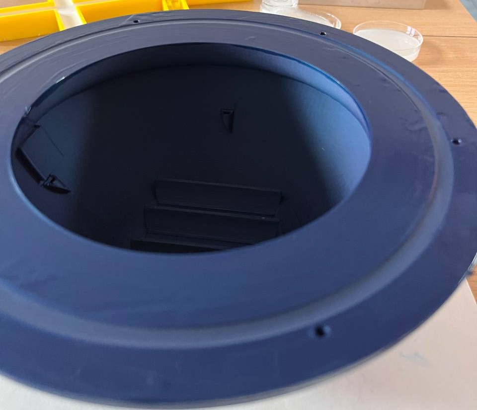
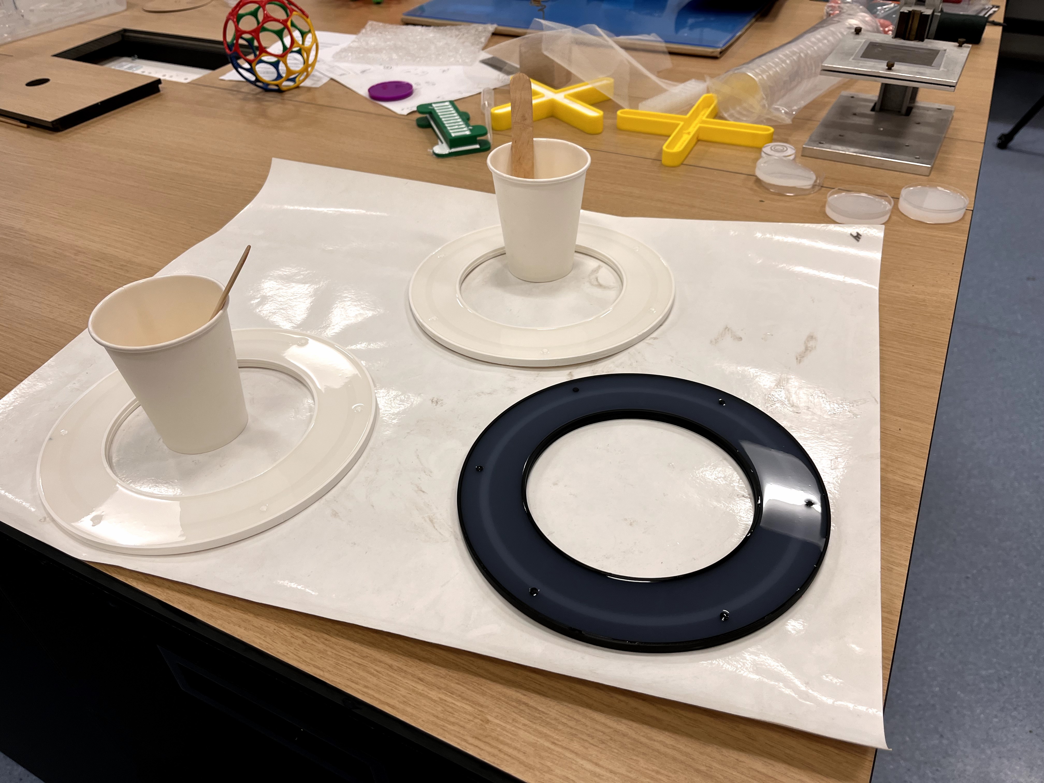
The solution of making the gasket in the body of the buoy itself was not effective, it is too small and does not compress. So I decided to cast a gasket separately so I could vary the height or shape according to my needs.
After several tests with different materials, I determined that the one indicated for its hardness and flexibility is OOMO0 25
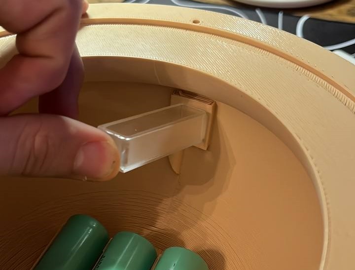
In the near future I will include an extraction system to perform spectral processing of a water sample deposited into a quartz couvette"not included in this version due to time issues, but it is the next Milestone
List of materials used
| Components | Made or buy | Price | fabrications Sistem | Design |
|---|---|---|---|---|
| body | made | --- | 3D printer | 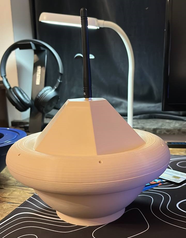 |
| joint | made | --- | Molding and Casting |  |
| electronic design | made | --- | cnc milling |  |
| Gayway | made | --- | 3d printer |  |
| temperature sensor | buy | 3.72€ | --- |  |
| pressure sensor | buy | 9.09€ | --- |  |
| 3xbatteries 18650 | buy | 7.5€ | --- |  |
| 2xHeltec esp32 LoRa V3 | buy | 50€ | --- | 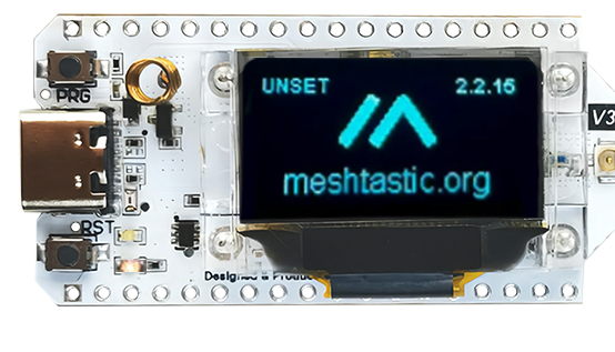 |
| Li-Po Battery 3.7V | buy | 6.2€ | --- | 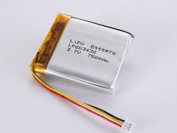 |
Results
Project dessemination
As I explained in the IP week., to maintain control over the use of my work, I have selected the “Creative Commons Attribution - Non Commercial - CC-BY-NC” license. This license permits others to use, share, and adapt my work for non-commercial purposes while requiring attribution to me. The license was chosen using the Creative Commons Chooser.

Slide
