Computer-Aided Design
Simple??
Ok…As I always say, the first thing is the design.
The idea from which everything starts must be very clear because this will be what will define dimensions, parts and pieces, geometry, etc. (although later the tests in the field destroy the original design). The design is the starting point of any project, and must reflect the problem to be solved, the objectives to be pursued, the requirements that must be met and the limitations that must be respected. A good design must be coherent, functional, aesthetic and feasible. To develop the design, different tools can be used, such as sketches, diagrams, models, simulations, etc. Design is not a linear process, but an iterative one, which involves constant revisions, improvements and validations. Design is a creative activity, but also technical and scientific, which requires specific knowledge, skills and attitudes.😊 In a world saturated with ideas and creations, reaching 2023 and maintaining originality is an arduous task. We live in an era where information and ideas are shared at an unprecedented speed. In this context, it is not uncommon for creators to take inspiration from existing works to develop their own projects. In your specific case, the lack of experience with boats led me to base it on an already known and proven design. This is not necessarily negative; Learning and taking inspiration from others can be a crucial step to innovation. The key is how those borrowed elements are integrated, adapted and improved to create something new and valuable.
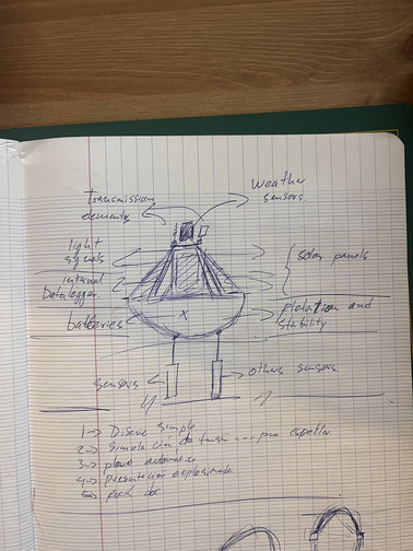
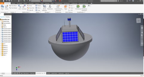
With this clear, I proceeded to make a sketch by hand to have more clarity about my project. The sketch helped me put my concept on paper, and to define the components and functions of each part. In the image you have sent you can see the sketch I made, which consists of a design of a floating device equipped with various sensors and elements to collect and transmit data. The sketch has annotations indicating the names and characteristics of each element, such as solar panels, batteries, data logger, light signals, transmission elements, weather sensors, and other sensors. The sketch is a preliminary and conceptual step, which allowed me to better visualize the structure and functionality of my device, and which helped me identify areas that needed more attention and refinement.

Getting started in Inventor
The first thing we will do is go to the Autodesk website and download the Software Inventor, we fill out the questionnaire to demonstrate that we will not use it for commercial purposes and we proceed to install it.
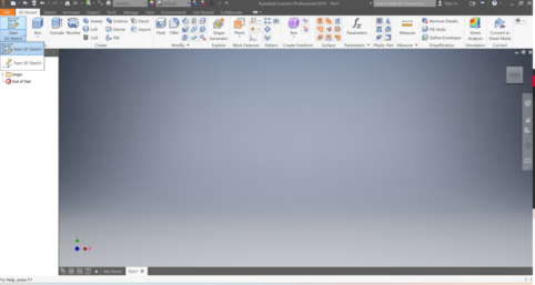
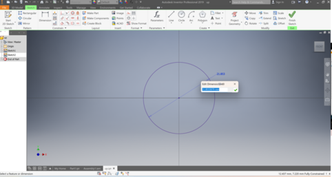
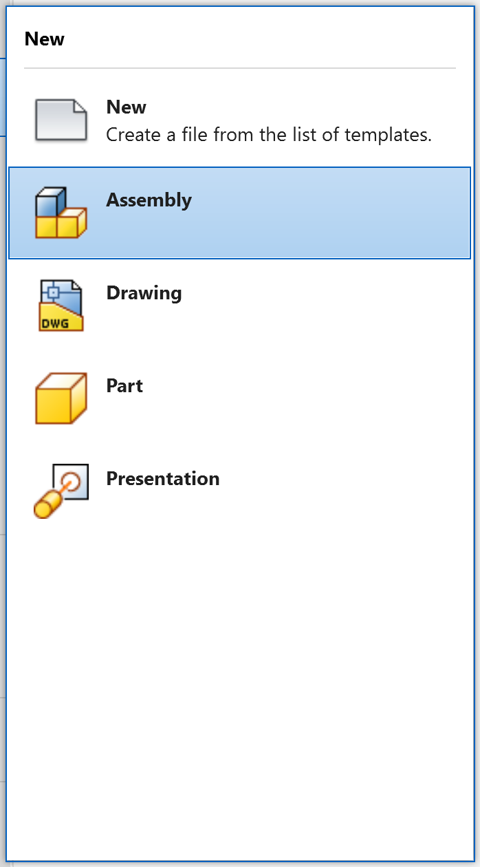
To start designing our device, we have to create a new part in the 3D modeling program we are using. To do this, we select the “Part” option in the main menu, and a window will open with a blank workspace. Here we can draw the basic shapes of our design, using the 2D sketch tools that the program offers us. Once inside Sketch 2D, we can choose between different types of lines, curves, circles, rectangles, etc. to create the outline of our part. We can also apply constraints and dimensions to define the dimensions and relationships between sketch elements. When we have finished drawing our 2D sketch, we are ready to move on to the next step, which is extruding or revolving it to turn it into a 3D part.
In this case, we are going to start at the bottom of the design, which is shaped like a semisphere. To create this shape. First, we have to make an arc in the 2D sketch that represents half of a circle. To do this, we will use the 2D sketch tools that the program offers us, such as the Arc tool. Next, we have to give the sketch the third dimension, to turn it into a 3D piece. To do this, we will use the Revolve tool, which allows us to rotate the sketch around an axis and create a solid of revolution. Thus, we will obtain the shape of a semisphere, which will be the basis of our design.
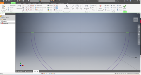
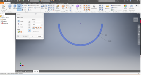
In this step, we have applied the revolve tool to give the third dimension to our 2D sketch. The revolution tool allows us to rotate the sketch around an axis and create a revolution solid. In the image below, you can see the result of this process. We have configured the tool to make a 180 degree revolution, which has resulted in a hemispherical shape. If we had chosen a 360 degree revolution, the resulting shape would have been a complete sphere.
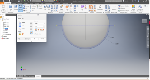
After creating the hemisphere with the revolve tool, the next step is to add some edges to give it a more defined and structured look. The extrusion tool allows us to create a 3D object from a 2D profile, giving it a certain height. In this case, we have drawn two circles at the bottom of the hemisphere, using the 2D sketch tools that the program offers us. Then, we have selected the extrusion tool and adjusted the parameters such as profile, distance, angle and direction. Thus, we have created a hollow cylinder that surrounds the hemisphere, forming the edge. I have checked the thickness and material of the edges, to make sure they are durable and aesthetic enough. I have also made some fine adjustments using the tools available in the program, such as the chamfer tool. In this way, we have managed to give a more professional and detailed finish to our design.
Another important aspect to take into account is the use of parameters. Parameters are numerical values that control the properties of model elements. Parameters allow us to create relationships between elements, so that if we change one, the others adjust automatically. This makes it easier for us to design and modify our model, since we do not have to change each element individually. However, you also have to be careful when setting the parameters, as they can cause conflicts or errors if they are not consistent or logical. Therefore, it is important to understand well how the parameters work and how they affect the model. In the next steps, we will see in more detail how to use parameters to create shapes that are dependent on each other.
Next piece
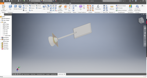
Next, we proceed to design the second piece, which will be part of our project. To do this, we return to the beginning of the 3D modeling program, where we can create a new part or open an existing one. In this case, we create a new piece, following the same steps that we have already described previously. That is, we select the “Part” option in the main menu, we make a 2D sketch of the shape we want, and we give it the third dimension with the appropriate tool. Thus, we create the 3D model of the second piece, adding the details and modifications that are necessary.
How can we use the parameters of one part in another?.
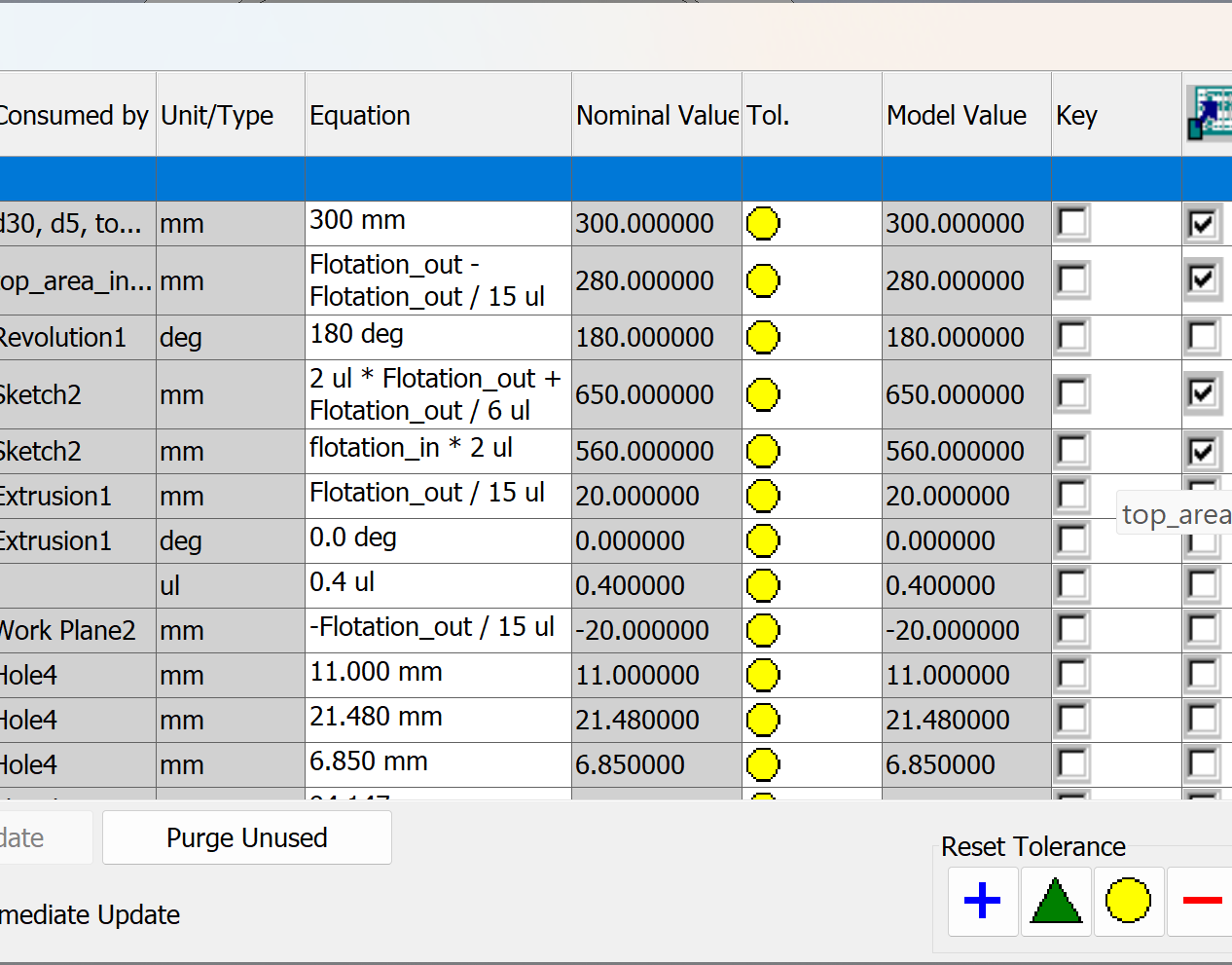
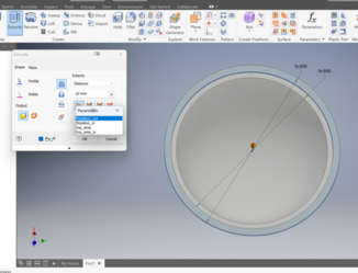
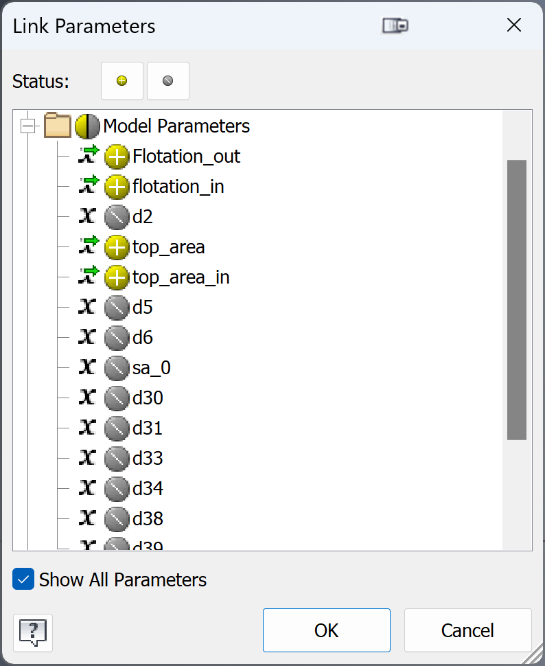
In order to use the parameters that we have defined in the previous model, we have to export them to a file that we can use in the new model. To do this, we have to go to the previous model and open the Parameters section, where we can see and edit all the numerical values that control our design. In this section, there is an export box that allows us to select the parameters that we want to export. We check the box of the parameters that interest us, and then we click on the export button. Thus, we save the parameters in a file with a format compatible with the 3D modeling program we are using. This way, we can import the parameters into the new model and use them to create relationships between the parts.In a world saturated with ideas and creations, reaching 2023 and maintaining originality is an arduous task. We live in an era where information and ideas are shared at an unprecedented speed. In this context, it is not uncommon for creators to take inspiration from existing works to develop their own projects. In your specific case, the lack of experience with boats led me to base it on an already known and proven design. This is not necessarily negative; Learning and taking inspiration from others can be a crucial step to innovation. The key is how those borrowed elements are integrated, adapted and improved to create something new and valuable.
After exporting the parameters from the old model, we have to import them into the new model in order to use them. To do this, we have to go to the part we are designing and open the Parameters section, where we can see and edit all the numerical values that control our design. In this section, there is an import button that allows us to select the file that contains the parameters we want to use. By clicking on the button, a window will open where we can choose the file and parameters we want to import. Once we have selected the parameters we are interested in, we click accept and the parameters will be added to our model. Thus, we can use the imported parameters to create relationships between the pieces of our project
Always Iterating
Don't worry, it's normal that sometimes you have to go back and modify your design. The important thing is that you learn from your mistakes and correct them. To return to model 1, just open the file you saved previously and make the changes you need. Remember that you can use parameters to adjust the dimensions and relationships between parts. In this case I didn't think about how the pieces would come together so we'll go back and do it.
We returned to designing part 2.
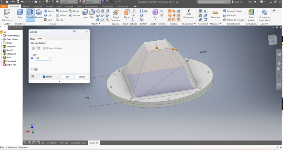
Now that we have imported the parameters from the previous model, we can use them to create the top part of the design. Parameters allow us to control the dimensions and relationships between the elements of the model, and thus create parts that adapt to our concept. To create the top part of the design, we will use the 3D modeling tools that we already know, such as the sketch tool, extrude tool, revolve tool, chamfer tool, etc. With these tools, we can draw and modify the shape of the upper part, adding the details and characteristics we want. We can also use the imported parameters to adjust the size and position of the top part, and to make it match the bottom part. Thus, we will be able to create a coherent and harmonious design.
Before concluding piece 2…let's talk about the assembly
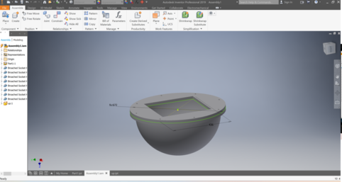
When we design a project in 3D, we have to take into account how it will be built in reality. If the project is made up of several pieces that are joined together, it does not make sense to design it as a single piece, since that would make its manufacturing and assembly difficult. Therefore, it is best to design each piece separately, and then assemble them in a different file. To do this, we have to create a new file in the 3D modeling program we are using, but this time it will not be a Part, but an Assembly. An Assembly is a type of file that allows us to put together several pieces and define the relationships between them, such as position, orientation, movement, etc. This way, we can see how our final project will look, and check if there are any errors or conflicts between the pieces. To create an Assembly, we have to follow the steps indicated by the 3D modeling program. Generally, these steps are: select the Assembly option in the main menu, add the parts we want to assemble, and apply the corresponding assembly relationships. Assembly relationships are constraints that control how parts relate to each other, such as coincidence, alignment, tangency, contact, etc. We can use the tools that the program offers us to create and modify assembly relationships, and thus achieve the result we are looking for.
How about some libraries?
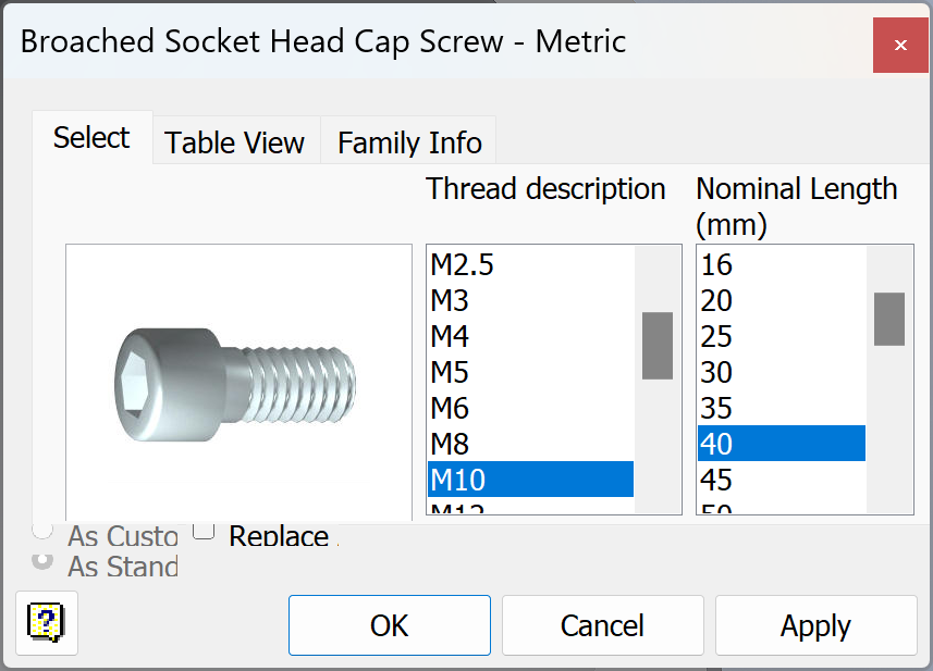
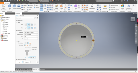
To join the pieces of our 3D model, we are going to use screws to ensure the fixation and resistance of the structure. To do this, we have to prepare the holes in the pieces where the screws will go, and then place the screws in the appropriate place. To make the holes, we will use the drilling tool, which allows us to create cylindrical or conical holes in the pieces. We can adjust the tool parameters such as diameter, depth, angle and hole position. We can also use the parameters that we imported from the previous model, to ensure that the holes match those of the other piece. Once we have made the holes, we can place the screws in them, using the assembly tool. This tool allows us to join two or more pieces using fastening elements, such as screws, nuts, rivets, etc. We can choose the type, size and material of the screws, and the tool will automatically place them in the holes we have selected. Thus, we will be able to join the pieces precisely and efficiently.
To assemble the parts of our project, we have to load them into the Assembly file we created. To do this, we use the “Place” section, which allows us to access the libraries where the pieces that we have designed or those that we have downloaded from external sources are stored. In the libraries, we can select the parts we want to use, and the program will place them in the workspace. We can choose between the commercial versions we need, depending on the type, size and material of the parts. Thus, we will be able to have all the pieces that are part of our design, and proceed to join them with the assembly relationships. After loading the parts that we have designed in the Assembly file, we have to define how they are going to be joined together. To do this, we use assembly relationships, which are constraints that control the position, orientation, and movement of parts. In this case, it's easy to establish assembly relationships, because we're going to use the Constrains tool, which allows us to match part elements, such as screws and holes. With this tool, we only have to select the elements we want to match, and the program will automatically align them. Thus, we can join the pieces precisely and easily.
After assembling the pieces using the screws and holes, we have to check that they fit perfectly. To do this, we can use the inspection and analysis tools offered by the 3D modeling program. These tools allow us to measure dimensions, angles, distances and interferences between pieces. This way, we can verify that there are no errors or conflicts that affect the operation or aesthetics of our design. Once we have verified that the pieces fit together perfectly, we can finish designing part 2. To do this, we can use the same tools that we used to design part 1, such as the sketch tool, the extrusion tool, the tool of revolution, etc. We can also use the parameters that we have imported from the previous model, to ensure that part 2 is compatible with part 1. Thus, we can create the shape and details of part 2, following the concept that we have defined for our project.
A little realism
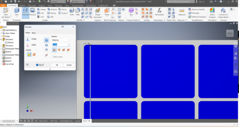
In this section, we are going to design the solar panels that will power our device. Solar panels are devices that convert sunlight into electricity, and are made up of solar cells that capture solar radiation. To design the solar panels, we have to take into account the design requirement that we have established, which is that we need about 5W in each panel. Watts (W) are a unit of power that indicates the amount of energy a device produces or consumes per unit of time. To know how many watts a solar panel produces, we have to multiply the voltage (V) by the intensity (A) generated by the panel. To know the dimensions of the solar panels we need, we have to consult the literature or sources of information that tell us the characteristics of the different types of solar panels that exist on the market. According to the search results I have obtained, 5W solar panels usually have a voltage of 12V and an intensity of 0.3A. The dimensions of these panels vary depending on the manufacturer and technology, but generally range between 250 x 186 x 17 mm and 320 x 200 x 18 mm. These panels are small and lightweight, and can be used for low-power applications, such as lighting, electronics, or battery charging (just what we are looking for).
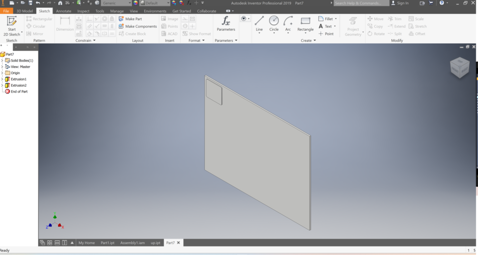
IWith the data obtained from the bibliography, we can proceed to design the solar panels that we need for our project. To do this, we will use the same 3D modeling program that we have used for the other pieces, and the same tools that we already know. The first step is to make a 2D sketch of the shape of the solar panels, using basic shapes such as rectangles or squares. We can adjust the dimensions of the figures according to the values we have consulted, and apply restrictions and dimensions to define the relationships between them. The second step is to give the third dimension to the 2D sketch, using the extrude tool. This tool allows us to create a 3D object from a 2D profile, giving it a certain height. We can choose the height we want for the solar panels, and the program will create them automatically. Thus, we can obtain a 3D piece that represents the solar panels of our design
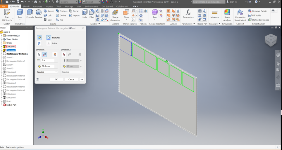
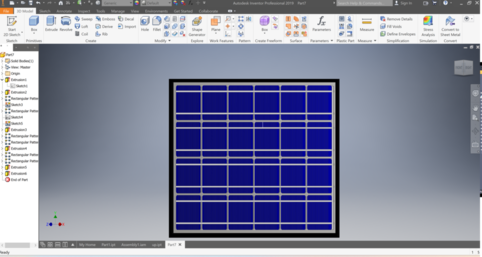
To create the solar panels, we need to replicate the small rectangle we designed into five other rectangles, to form an array of six solar cells. To do this, we will use a tool called Pattern, which allows us to create copies of an element following a defined pattern. The Pattern tool offers us several options to create the pattern, such as type, direction, distance, quantity and angle. We can adjust these parameters according to our needs, and the program will create the copies automatically. Thus, we can obtain a 3D piece that represents the solar panels of our design
And then that whole line in 3 more lines...
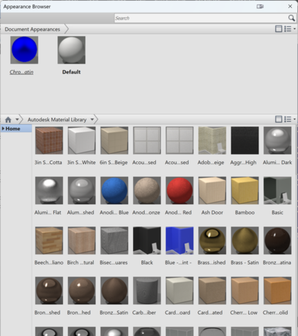
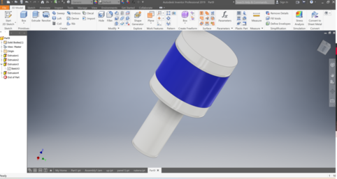
To give a more realistic look to our 3D design, we can apply color and material to the pieces we have created. Color and material determine what the surface of an object looks like, how it reflects light, and what texture it has. To apply color and material to the parts, we will use the material and color tool found at the top of the 3D modeling program interface. This tool allows us to choose from a variety of predefined colors and materials, or create our own. We can select the color and material that we like the most or that best fits our concept, and then paint the pieces with the paint bucket or drag and drop the material on the surface. Thus, we can customize the appearance of our 3D design, and make it more attractive and realistic.
After creating the basic shape of our 3D design, we can give it a little more detail using classic 3D modeling tools. These tools allow us to modify the surface of our model, adding curves, reliefs, textures, etc.
To complete our 3D design, we can add a frame that gives it a more realistic and finished look. The frame is a piece that surrounds the edge of our model, and can have different shapes, colors and materials. To create the frame, we can use the same tools that we have used for the other parts, such as the sketch tool, extrude tool, revolve tool, etc. We can also use the material and color tool, which allows us to choose from a variety of predefined colors and materials, or create our own. We can select the color and material that we like the most or that best suits our concept, and then paint the frame with the paint bucket or drag and drop the material on the surface. Thus, we can customize the appearance of our frame, and make it more attractive and realistic.
A few more pieces
All together
It is now time to join all the pieces, for them we will go to the assembly that we had created, we will import the new pieces and just as we have done before with the Constrains tool we will join our pieces.
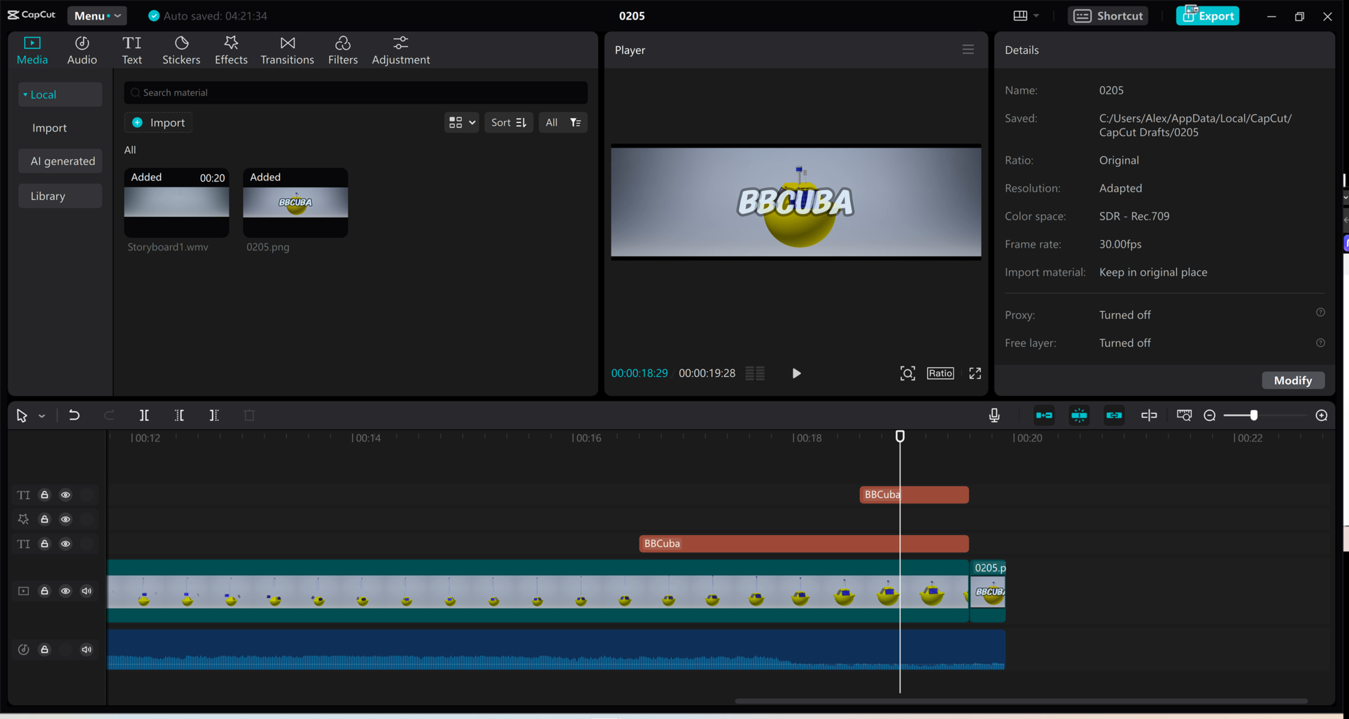
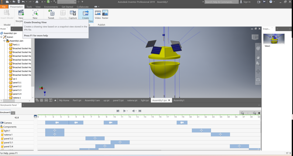
Later we will give it a little color (don't worry). Now, I'm going to do an animated exploded view of my smart buoy, to show how each part is assembled and disassembled. To do this, I will follow the following steps: I will open the assembly file of my smart buoy and save it as “Standard.ipn(mm)”, then I will create an exploded view of my smart buoy, moving each part to a suitable position to show its relation to the rest of the assembly, and I will create an animation of the breakdown of my smart buoy, adjusting the time, speed and sequence of each movement. Finally I will save and export my animation in the format I prefer, such as AVI, GIF or WMV.
The exploded animation will help me better explain the operation and structure of my smart buoy, and to facilitate its assembly and maintenance.
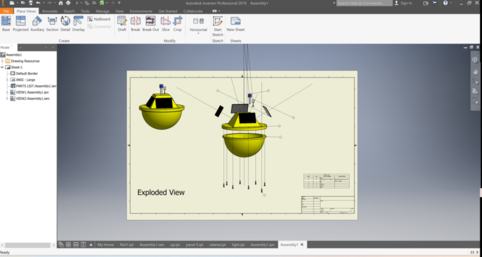
Once we have the exploded view we can make a plan with it and thus obtain a more professional and more replicable result. Although seeing it this way I realize that it lacks a little personality, but I have the solution...do you want a little more?
An original logo in Inkscape
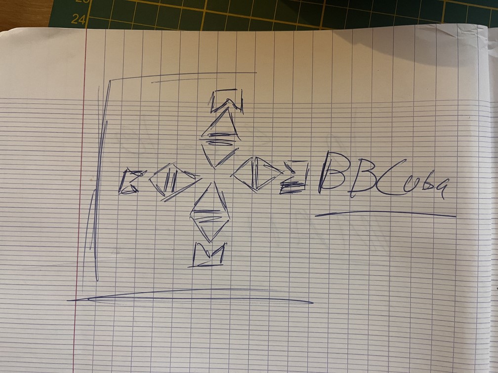
Before starting to draw anything, I will do it by hand. After several attempts we arrived at a version that I like.
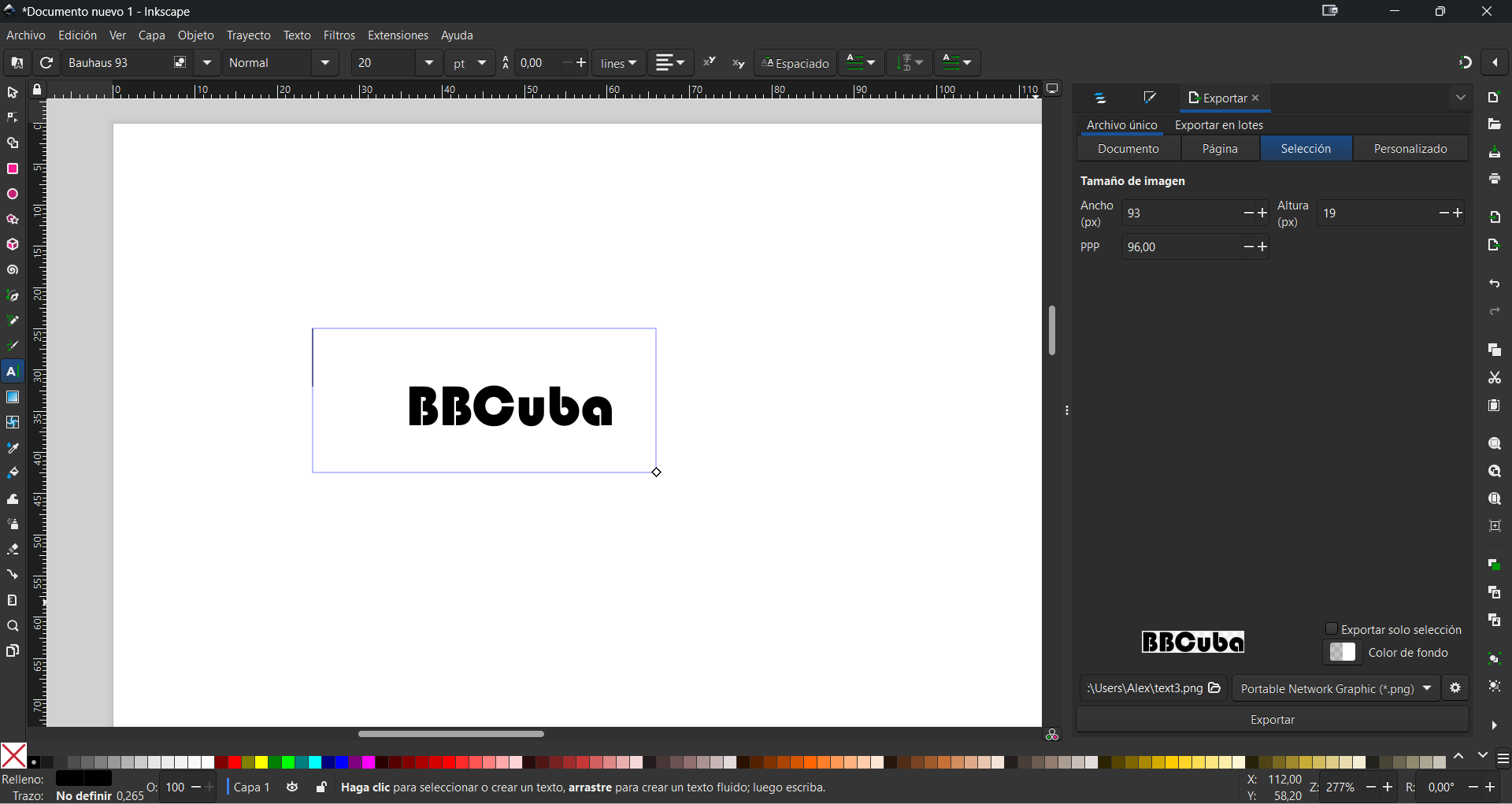
ANow let's go to the Inkscape website, download and install the program, it is quite intuitive so we will start with the basics, writing the name of the project
Since the designed logo is made up of simple geometric figures, let's start painting them, we will do it with lines so that they are not perfect and this way it is even more personal.
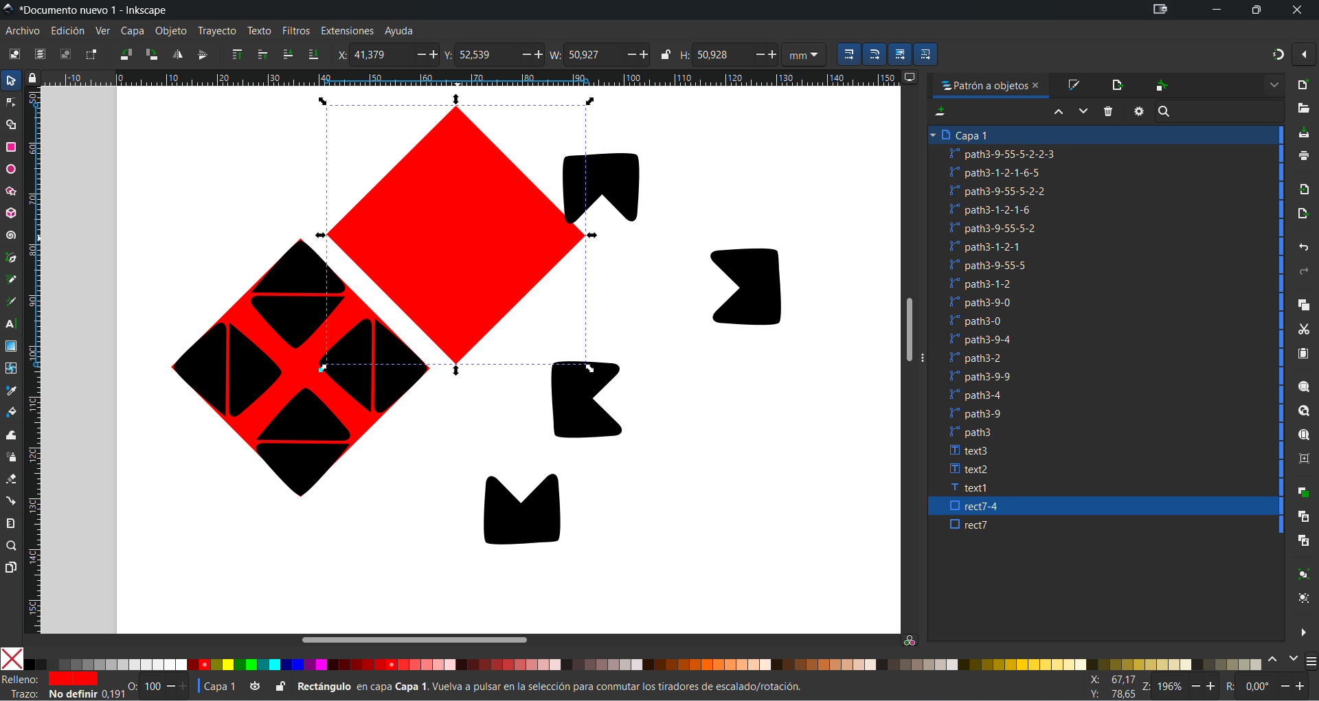
Once the figure is smoothed, it is ready to be replicated, but for this process we do need a guide, so we will make two squares, one inside and one outside.
Now we add color, erase the squares and place the name. The project has acquired 70% personality...haha
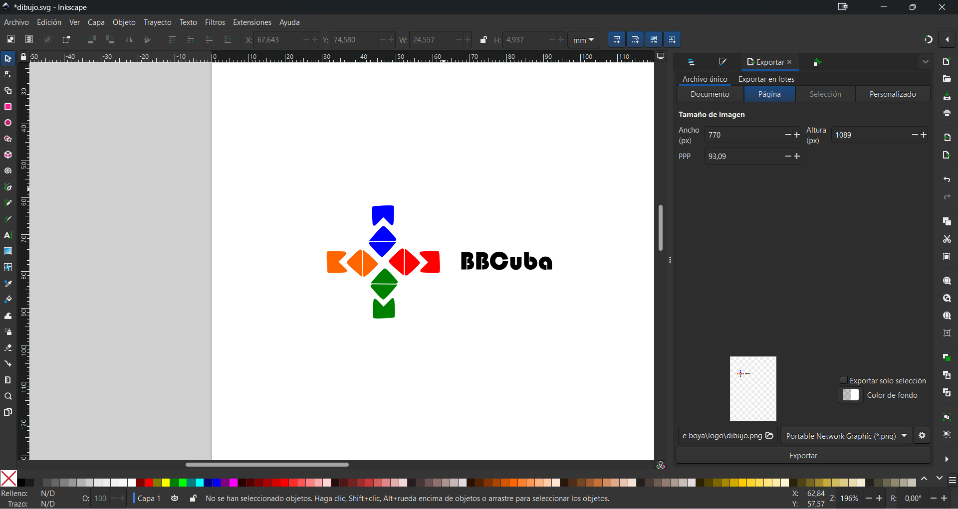
I think it looks spectacular
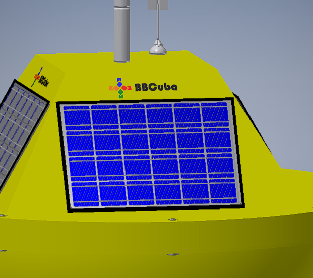
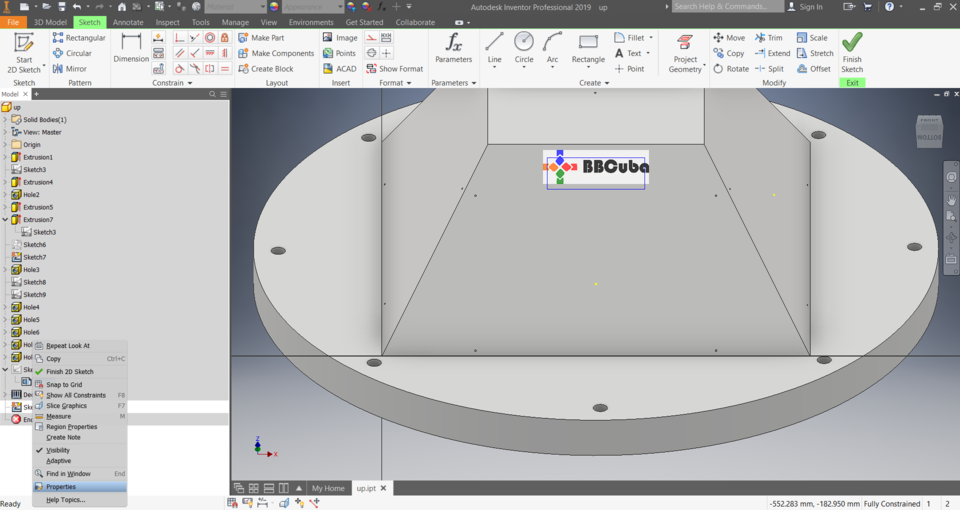
To create this effect we return to Inventor to part 2, import the newly created image in PNG format and tap on properties to remove the background. Finally we attach it to the piece with the Emboss tool.
Final touches
To make the video a little more epic we will use the Capcut tool, so we will add music and a final sign. In this link I leave all the files generated this week