Input Devices
Let's read something
Group assignment
The group's tasks: probe an input device's analog levels and digital signals fablab website.
General Objective
The objective of this week is to make a sweep of the most common input devices, their technologies and communication protocols, uses and some examples.
Input Devices
Input devices let the microprocessors interact with the world. Without it, a microprocessors would simply run its program with no way to respond to the external environment or user commands.There are many ways to insert information into the system, but for ME, these are the fundamental ones:
-Analog signals
-Digital signals
-Through protocols (I2C, 1 Wire, SPI, etc...).
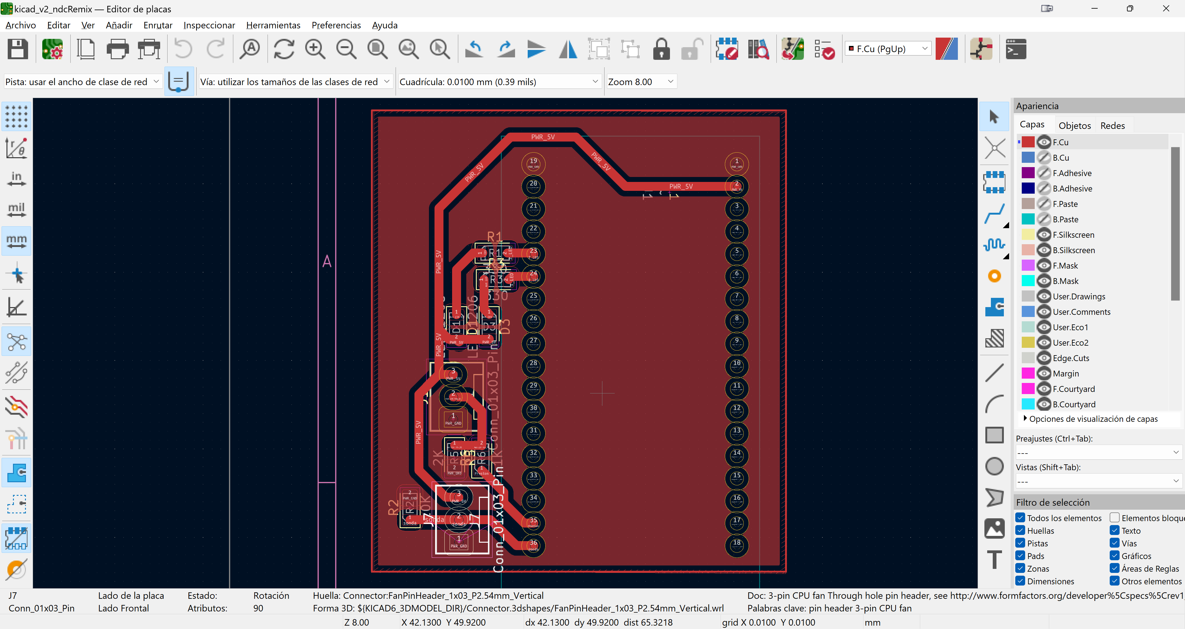
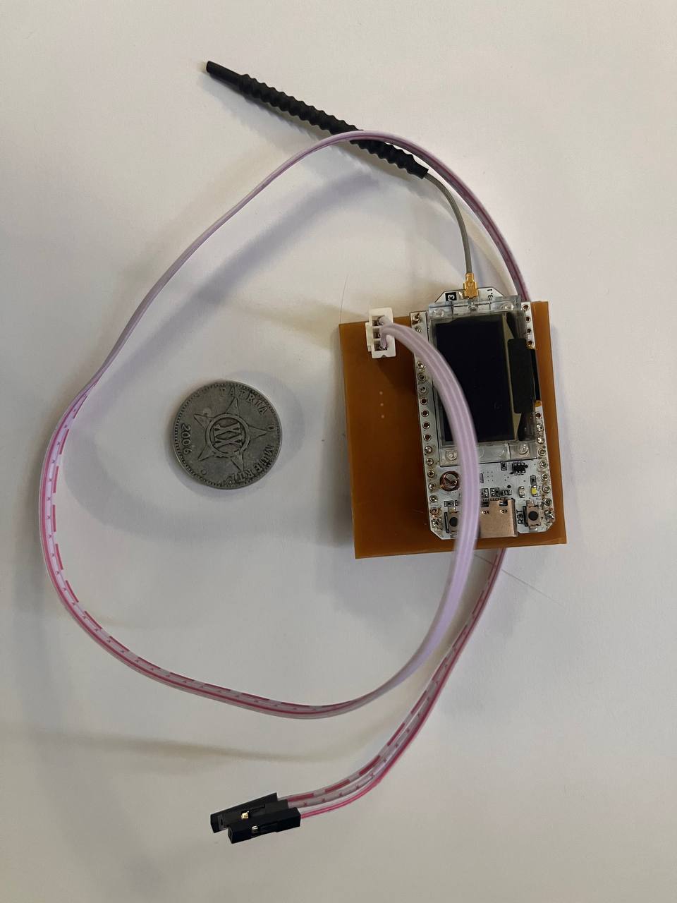
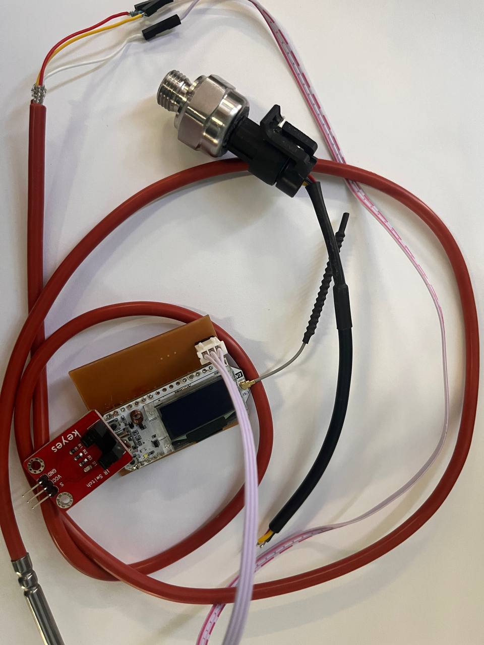
I made some additions, such as 2 LEDs, but this week it will only be necessary to use the 3 pins that I have marked in the photo...which would be a GND pin, a VDD pin and a signal pin. This Link you can download the PCB design
_V3.png)
The secret to being able to connect both an analog and a digital sensor to the same microcontroller pin is hidden in the power of the Heltec V3, being able to use all its GPIO pins both analog and digital, unlike traditional Arduinos that had a set well differentiated by function.

Remember that in order to program this microcontroller it is necessary to go to "preferences" and paste the following line in "Additional Boards Manager URLs":
https://raw.githubusercontent.com/espressif/arduino-esp32/gh-pages/package_esp32_index.json
Analog Sensors
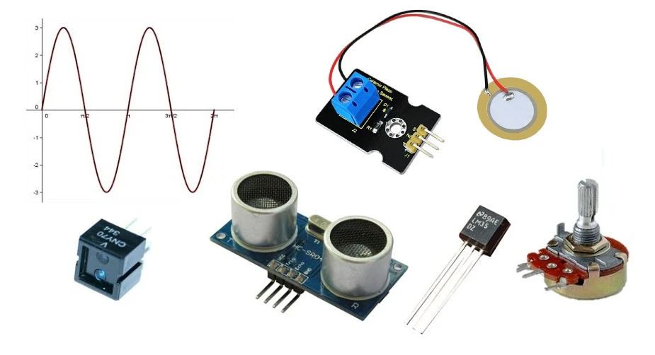
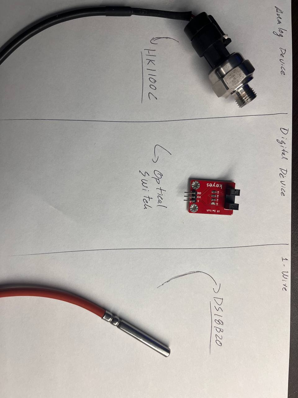
Analog sensors describe reality as we see it, by ranges of values, just like our senses that detect intensity, analog sensors detect changes in the magnitude they are sensing and convert it to a usable value of voltage or current, To better understand this phenomenon, I will use a pressure sensor and we will see how its behavior varies.
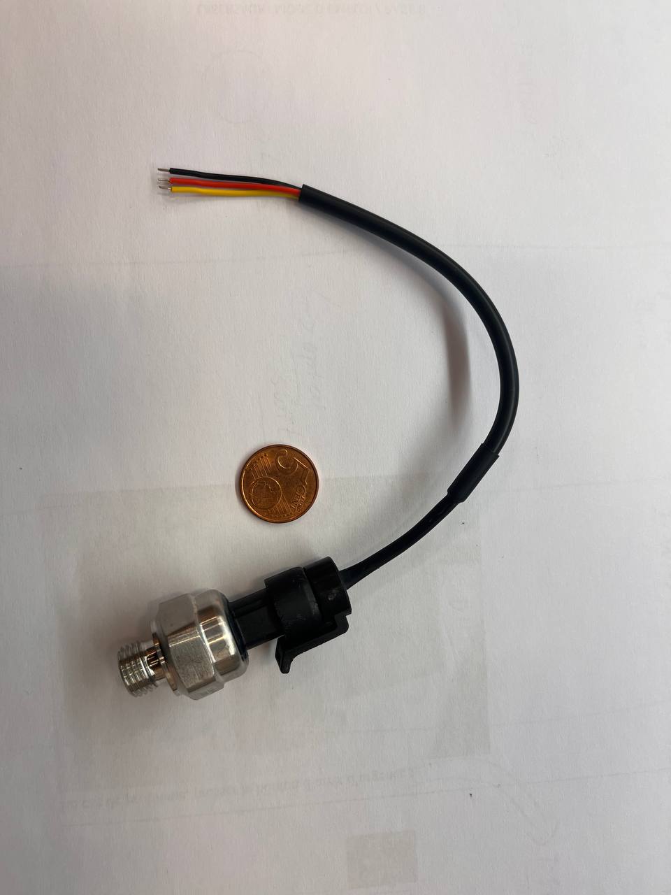
The HK1100C pressure sensor will give us a voltage value with the pressure variation, this value will be read by our microcontroller, in a range between 0 and the maximum resolution value of the processor, in this case 4095 (12 bits), then, like most sensors, it is governed by a formula from the manufacturer to obtain a useful value for us, that is, a pressure value.
The procedure for reading an analog sensor is to calculate its voltage value, which is the electrical magnitude that can generally be associated with the magnitude we are looking for. To read this value, the voltage divider formula is used and it is connected as follows:
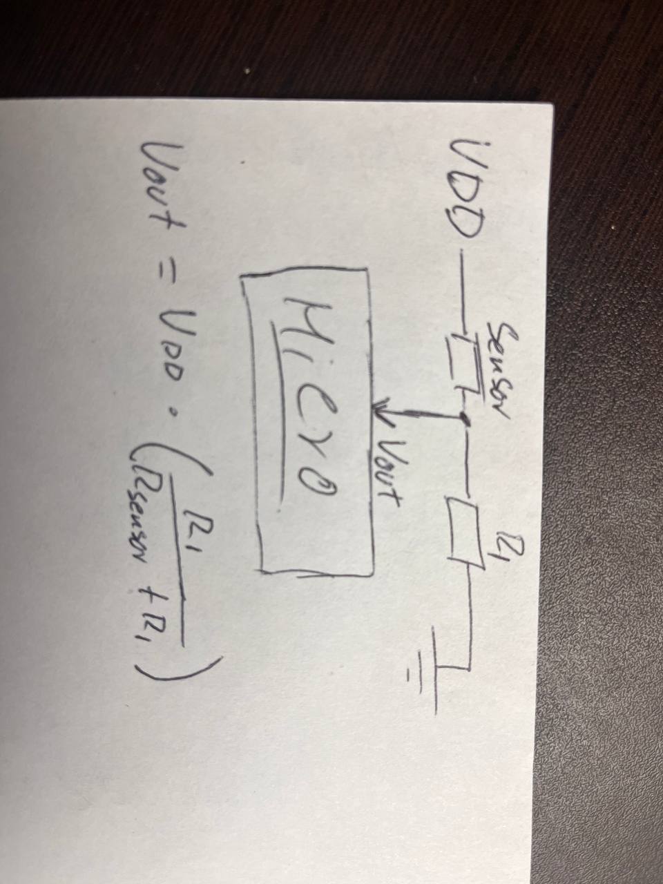
Although in the case of the HK1100C it is simpler since the divider is implemented in the sensor because I only had to read the value and apply a formula given by the manufacturer. For this formula it is necessary to know the value of the sensor in the min and the max to read. Since I do not have a way to measure these values, I did a search on the Internet and these seemed convincing to me.
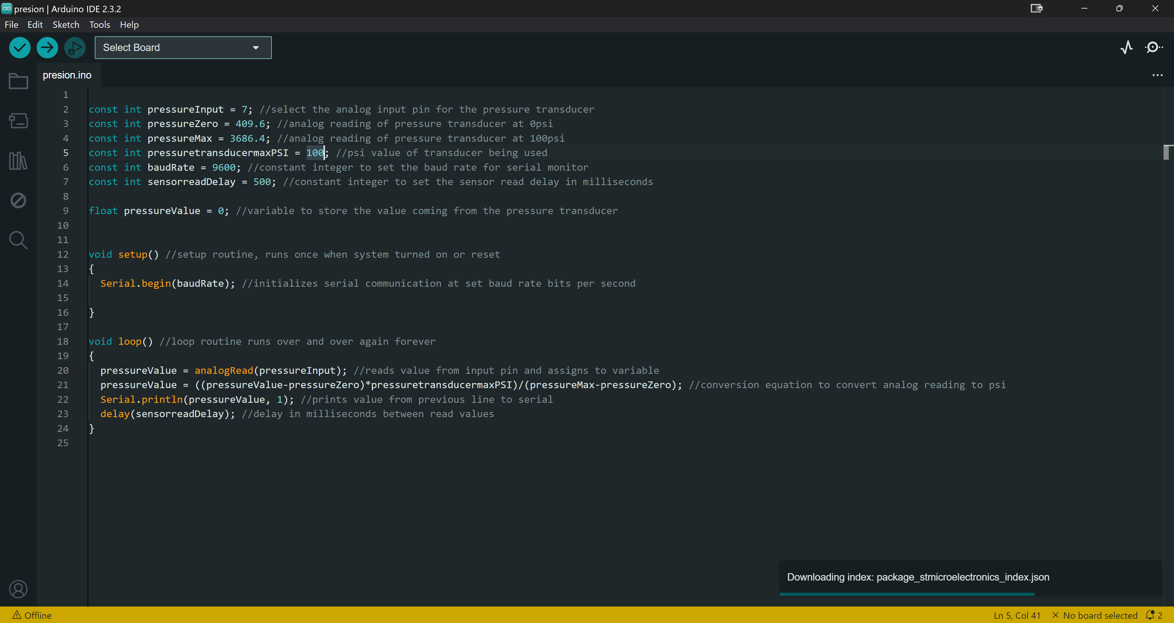
Result
In the following video we see how when sucking the sensor the reading goes from a relatively constant pressure value (ambient) to a low value.
Digital Sensor
Digital sensors describe reality in two ways, you could say that they only see life in two colors: black and white (bad joke...😅😅). They are used to define states and make counts and verifications. Unlike analog sensors, they do not provide a voltage range but only 2 values, 0 (which normally coincides with 0v) and 1 (which is normally the value of the sensor power supply: 3.3v, 5v, 12v, etc.).
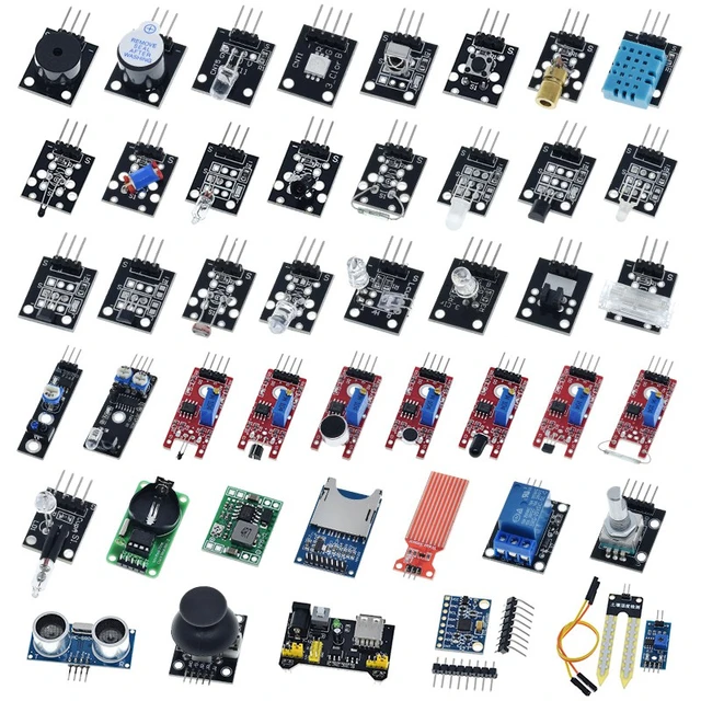
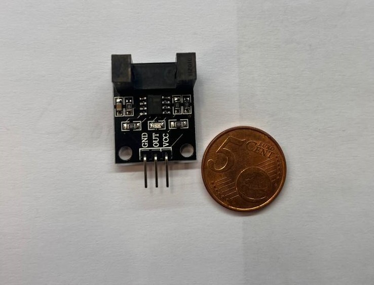
To give an example of this type of sensor, I have used the simplest and most common digital sensor: a switch, in this case optical, that will send a signal when you interrupt it and if not, well, it will do nothing...and it is in that case of nothing that measures must be taken.
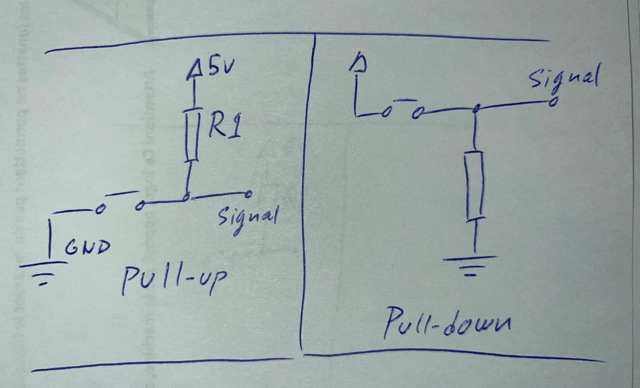
Connecting a digital sensor is an easy task but there is one detail to keep in mind, remember to put the corresponding resistor in Pull-up or Pull-down… it is nothing more than placing a resistor between the signal pin and the opposite value of GND or VDD, to that given by the sensor in its normal state, that is, if the sensor always gives VDD, we will connect a resistor to GND so that when it is activated it returns 0V. Otherwise, if the sensor returns 0V when it is activated then we connect a resistor between signal and 5V. Although in this case it is not necessary to make this type of resistor configuration since the sensor has it included in the PCB.
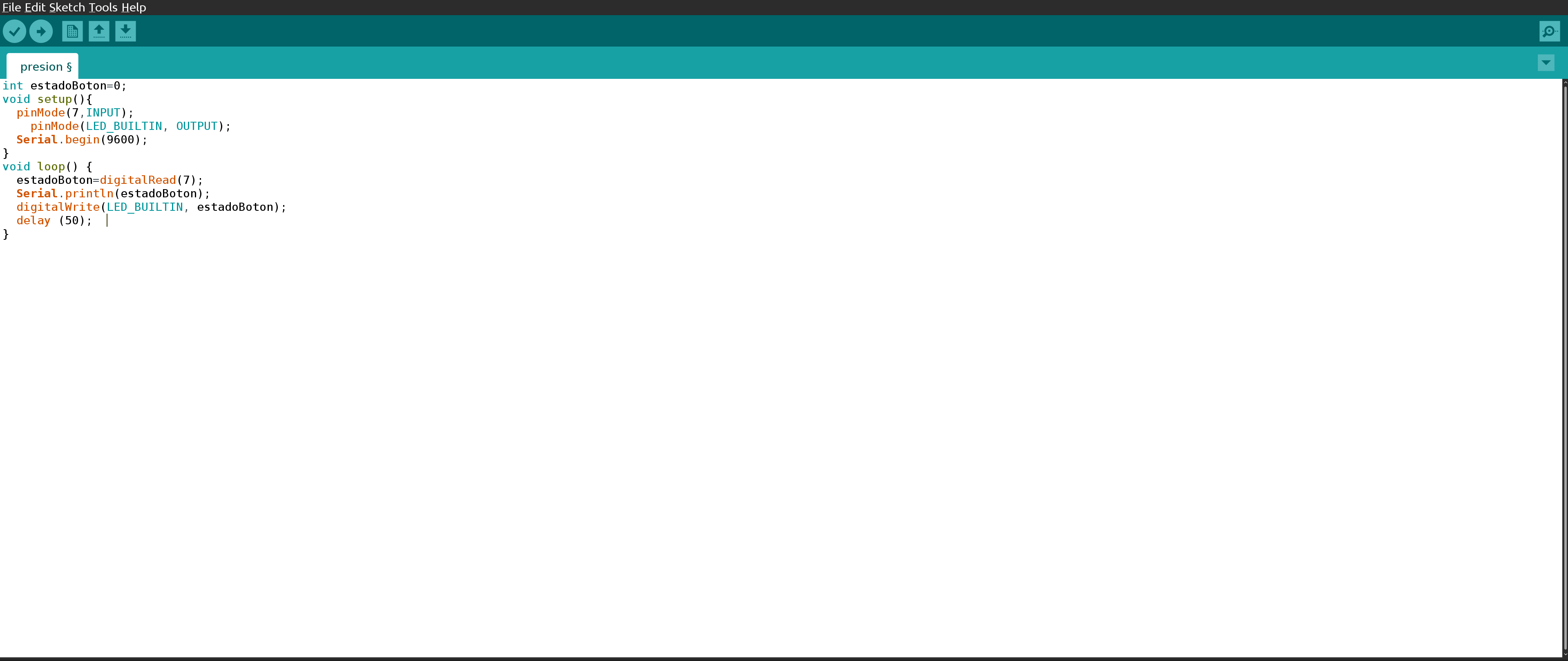
The programming is practically self-explanatory, I will read the value of the sensor, I will display it on the serial monitor at the same time that I turn on or off the default LED of the microcontroller depending on the sensor signal.
Result
The operation is very intuitive, but this same example with the LED is an approach to real projects such as light control or those.
1-Wire
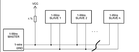
Analog and digital are the basis for reading any parameter, but over the years sensors are becoming more and more intelligent, and many of them have a signal conditioning stage and their own microcontroller. Usually, once they acquire this level of intelligence, a communication protocol is added to make working with them more comfortable and, above all, more standard; examples of these protocols can be: I2C, SPI, 1-Wire, among others. The latter is nothing more than a serial communication protocol based on a bus, a master and several slaves that feed a single data line. Of course, a common ground reference is necessary for all devices.
The basis of 1-Wire technology is a serial protocol that uses a single data line plus a ground reference for communication. 1-Wire is a voltage-based digital system that operates with two contacts (data and ground) for two-way half-duplex communication. Compared to other serial communication systems such as the aforementioned I2C, 1-Wire devices are designed for use in a momentary contact environment. That is, if they lose communication, they do not store data, they simply restart when they reconnect.
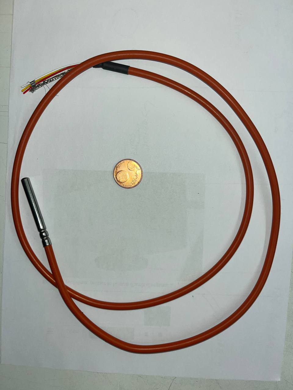
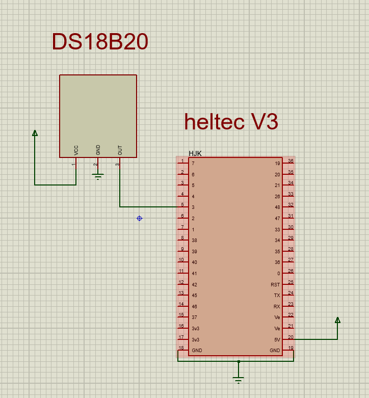
The device I used is the DS18B20 temperature sensor, its connection as we can see is to the power supply (which can be either 5v or 3.3v) and the 1-Wire bus pin to a pin on the microcontroller. In this case I connected it to pin 3 and in the PCB design I made I have access to pin 3 but in the following programming we will connect it to pin 7 which is the one we used to test both the optical switch and the pressure sensor.
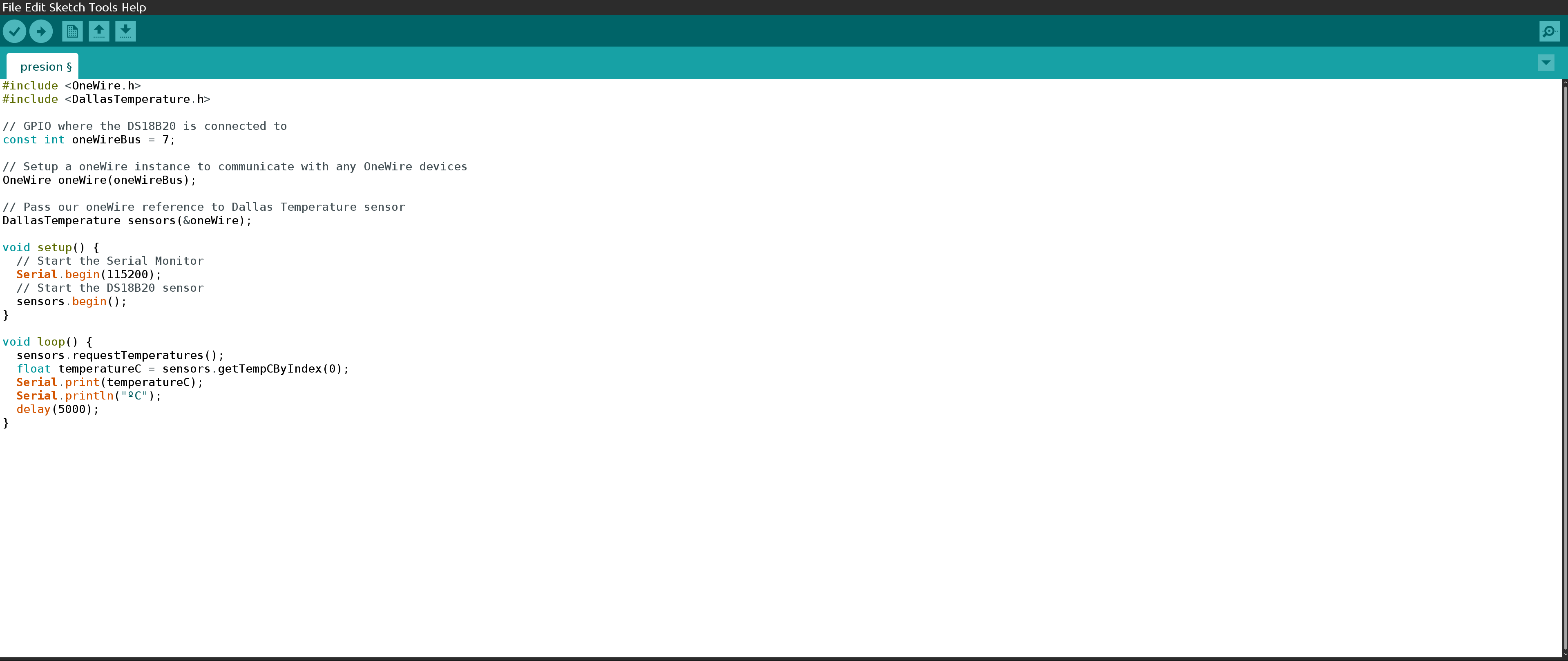
All sensors that have built-in communication protocols have their own library in Arduino, made by the manufacturer or by the community itself. In this case, it is necessary to install, in the Arduino library manager, the two libraries that we are using because they are not native to Arduino:
OneWire.h
DallasTemperature.h
As we can see, the use of the specific library for the sensor saves us a lot of work, just by calling a function I already have the temperature value.
Be careful
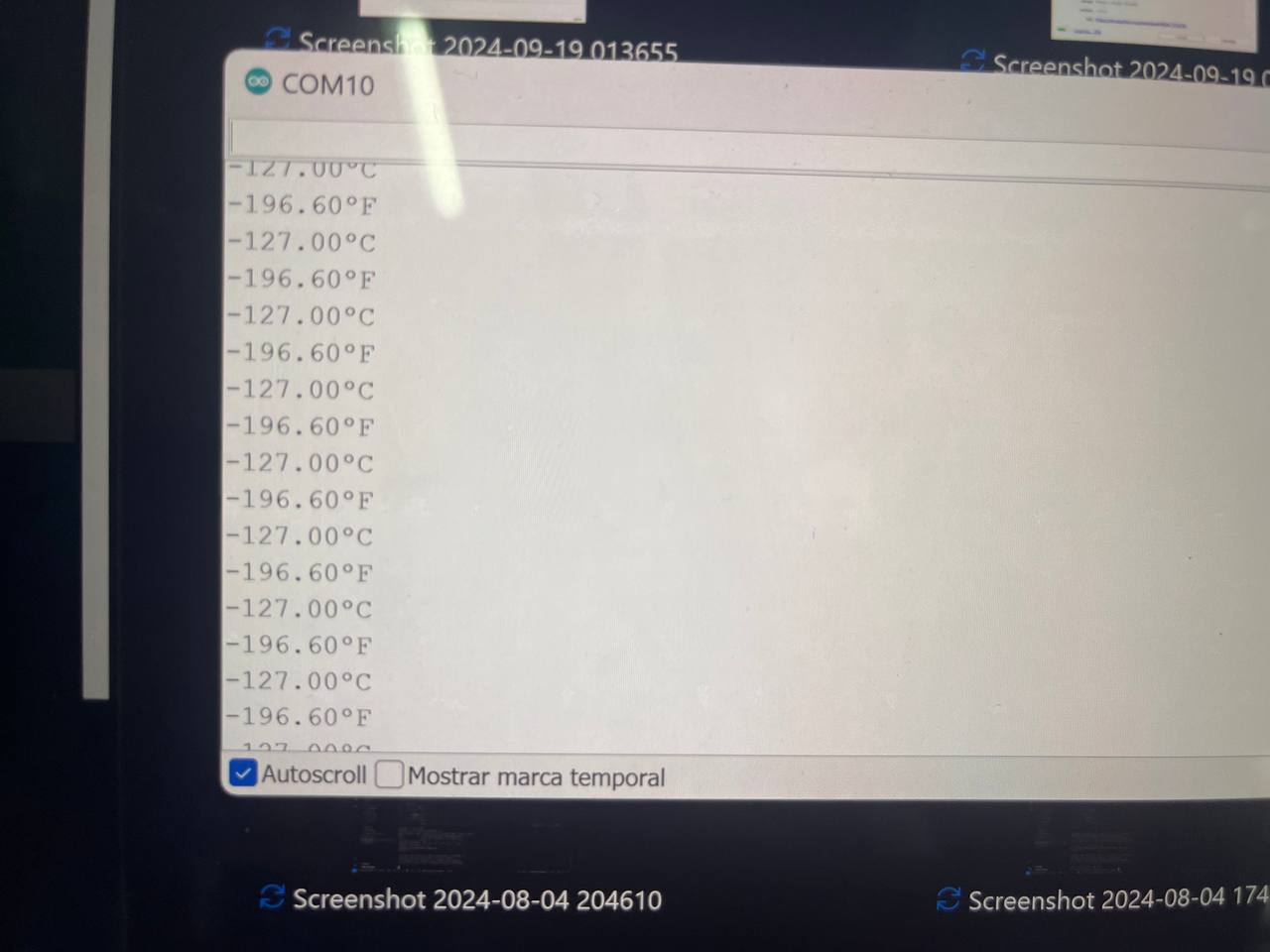
As soon as I ran the program, these are the values that the sensor gave me, and I think I'm not at the north pole😅😅...the issue is that 1-Wire sensors must be connected with a pull-up resistor (a concept that we already saw).
Result
Once the pull-up resistor was connected, the value was read without any problem. I had this meter in the laboratory and used it to check. As you can see, the readings are quite precise.
Conclusions
Each type of sensor with its respective technology has its advantages and disadvantages, it will depend greatly on the objectives of the project as well as the rest of the system components.All the files used this week are in this Link
