9. Output devices
Welcome to this week’s exploration of output devices. We’ll delve into understanding power consumption, measuring electrical outputs, and analyzing the behavior of different components.
Learning Outcomes:
- Demonstrate workflows used in controlling an output device(s) with MCU board you have designed.
Group Assignment Summary
For this week’s group assignment, we focused on measuring the power consumption of various output devices. Our primary tool for this task was the Instek GPD-3303D bench power supply, which provided stable output power and allowed us to control voltage and current settings.
DC Power Supply Specifications
We utilized the Instek GPD-3303D bench power supply with the following specifications:
-
Power Supply: Instek GPD-3303D
-
Number of Output Channels: 3
-
Maximum Voltage: 30V
-
Maximum Current: 3A per channel, 5A total
-
Current Measurement Accuracy: ±(0.1% + 2 digits)
Output Device 1: DC Motor
Our first output device was a DC motor, which converts electrical energy into mechanical energy. We powered the motor at 12V and observed a current draw of 0.04A. Additionally, when the motor was stalled at 12 volts, it drew a higher current of 1.29A.
Output Device 2: White LED
The second output device measured was a white LED. This LED operates within a voltage range of 3-3.4V. When powered at 3.2V, it drew a current of 0.02A.
Individual Assignment
Introduction
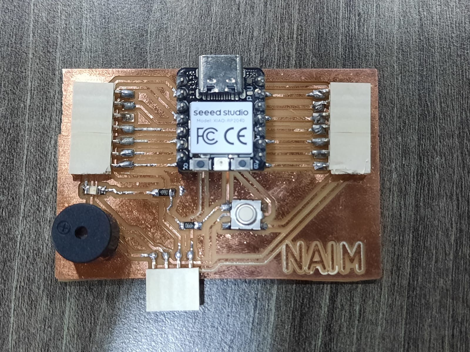
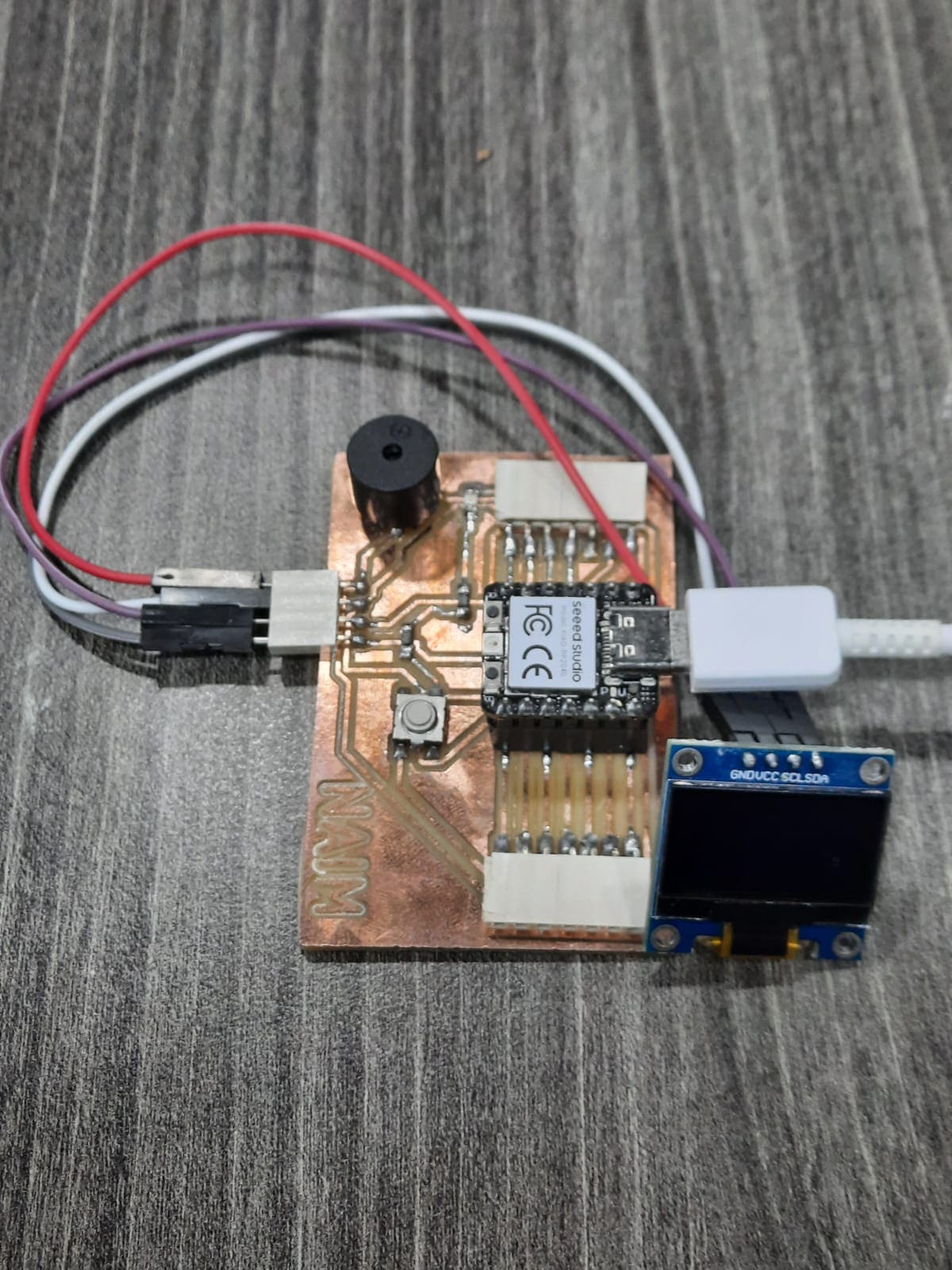
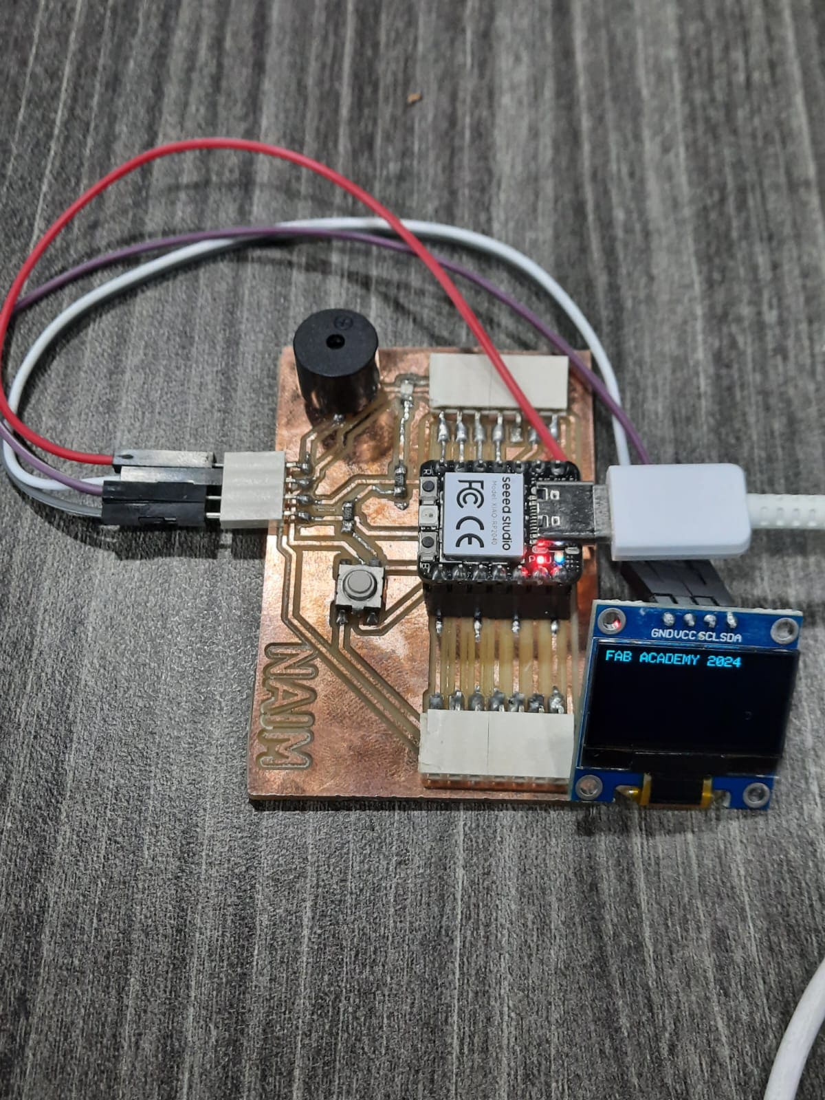
This week I explored various output devices using a the development board I designed, milled, and assembled in the electronics design week. This board is powered by a Xiao RP2040 microcontroller, offering a versatile platform for experimentation.
Setting Up Arduino IDE
- Connect the board to your computer using the USB cable.
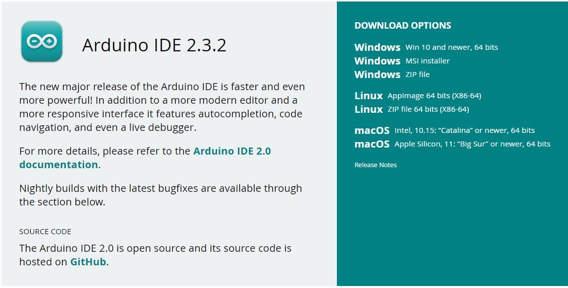
- Download and open the Arduino IDE.
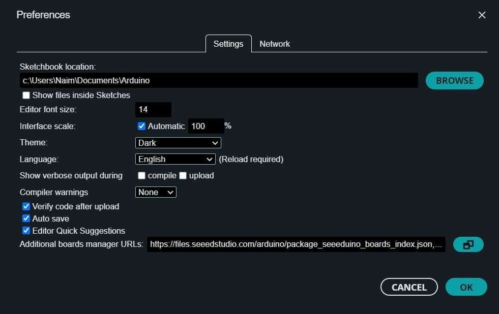
- Add Seeed Studio XIAO RP2040 board package to your Arduino IDE
Navigate to File > Preferences, and fill Additional Boards Manager URLs with the url below:
https://github.com/earlephilhower/arduino-pico/releases/download/global/package_rp2040_index.json
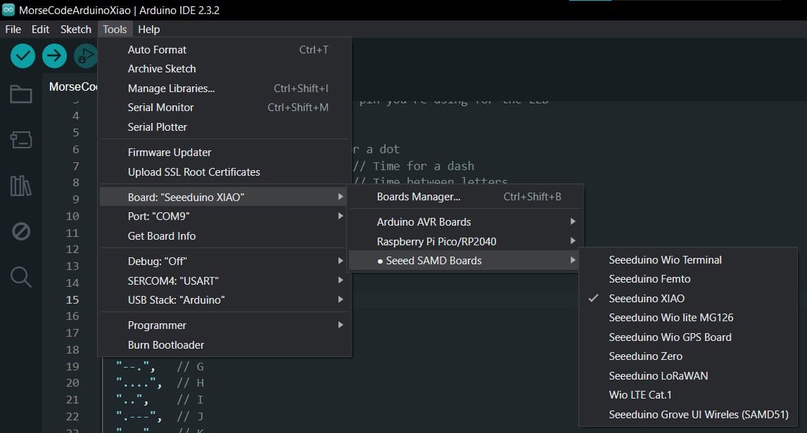
- Select your board and port.
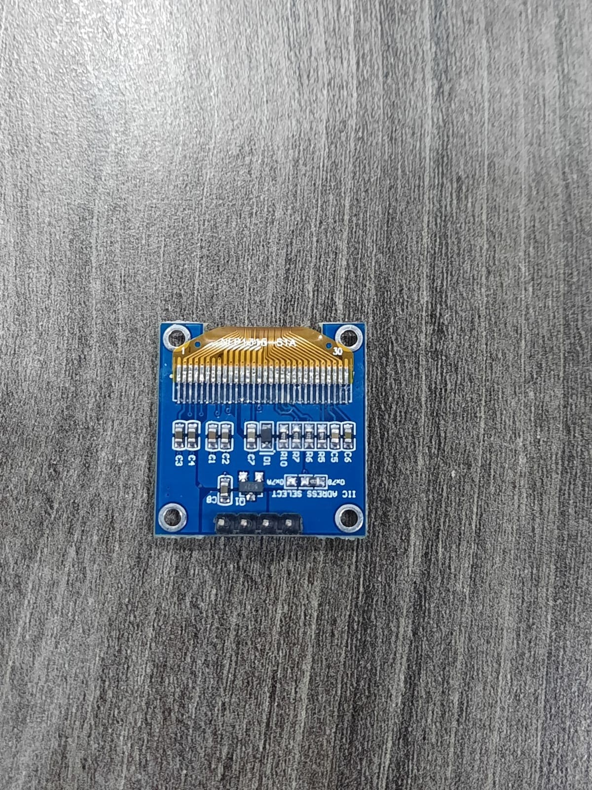
Output Device 1: NFP1315-51A OLED
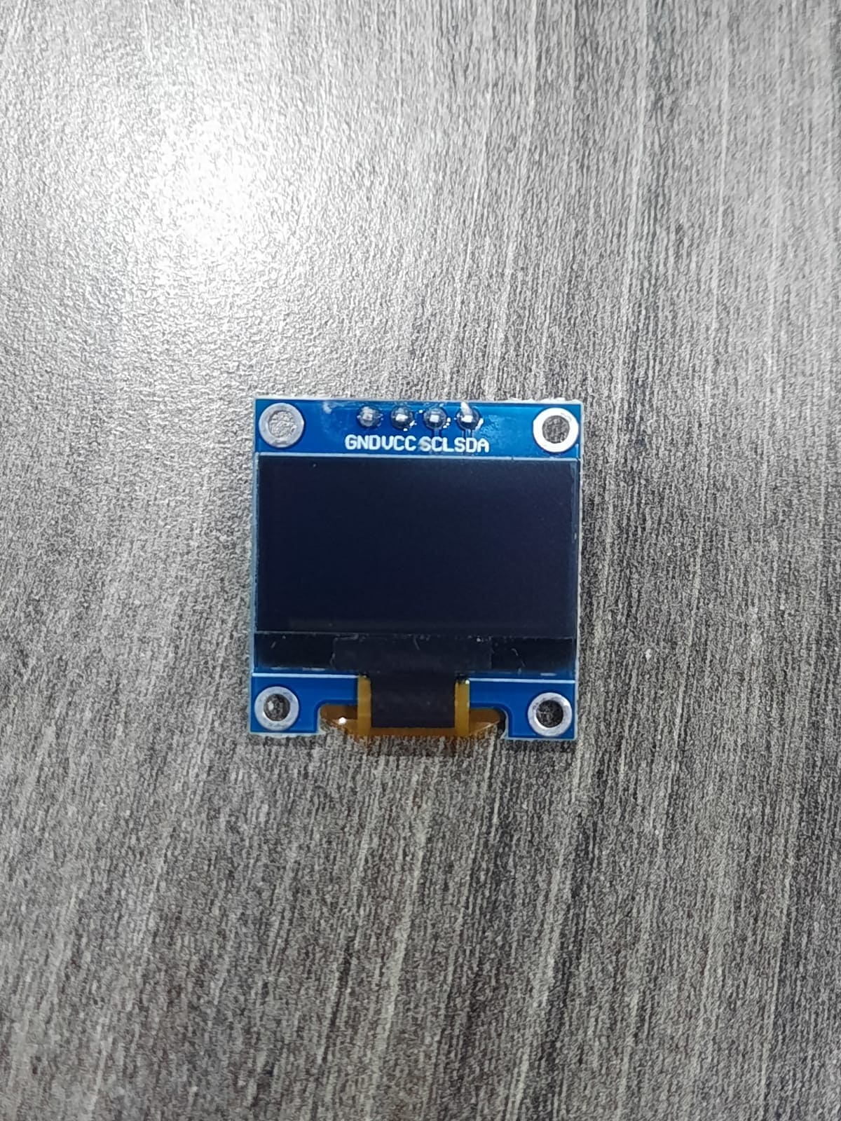
Setup and Initial Challenges
Setting up the NFP1315-51A OLED initially posed some challenges, particularly in obtaining the correct libraries required for interfacing with the microcontroller. However, with persistence and troubleshooting, I managed to overcome these hurdles and successfully activated the OLED display.
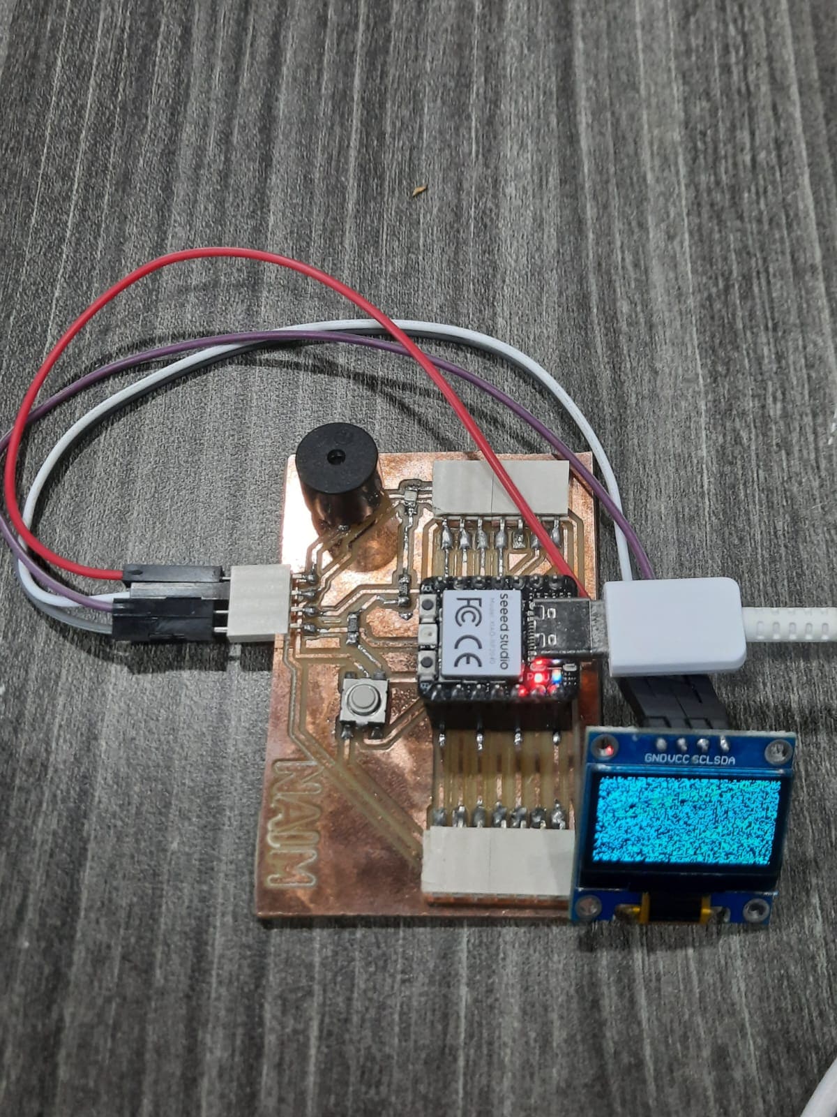
Initial Testing with Pre-programmed Message
I began by testing the OLED display with a pre-programmed message. Using Arduino IDE, I uploaded a simple code to the Xiao RP2040 microcontroller to display a predefined message on the OLED screen.
The Code:
#include <Wire.h>
#include <Adafruit_GFX.h>
#include <Adafruit_SSD1306.h>

#define SCREEN_WIDTH 128
#define SCREEN_HEIGHT 64
#define OLED_RESET    -1

Adafruit_SSD1306 display(SCREEN_WIDTH, SCREEN_HEIGHT, &Wire, OLED_RESET);

void setup() {
  Serial.begin(9600);

  if(!display.begin(SSD1306_SWITCHCAPVCC, 0x3C)) {
    Serial.println(F("SSD1306 allocation failed"));
    for(;;);
  }

  Serial.println(F("Display initialized successfully"));

  delay(2000);
  display.clearDisplay();
  display.setTextColor(WHITE);
}

void loop() {
  display.clearDisplay();

  // Display "Hello, World!" text
  display.setTextSize(2);
  display.setCursor(0,0);
  display.println("Hello,");
  display.println("World!");

  display.display();
  delay(1000); // Delay for 1 second before updating the display
}
Experimentation with Text Size and Cursor Position
During the testing phase, I experimented with adjusting the text size and setting the cursor position on the OLED display. This allowed me to customize the appearance of the displayed text and explore different layouts.
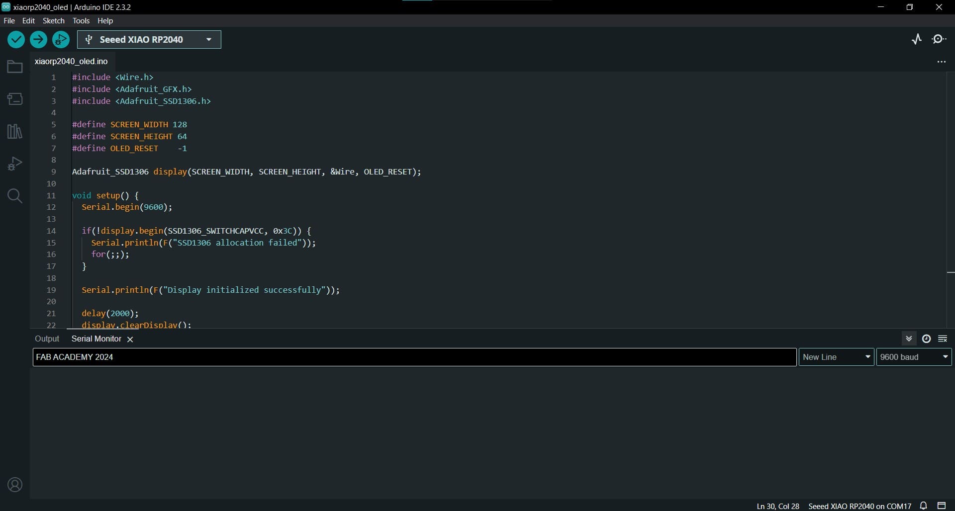
Enhancements: Dynamic Text Input
To make the OLED display more interactive, I modified the code to accept text input via the Serial Monitor in Arduino IDE. This allowed me to update the OLED display instantly with the entered text.
The Code:
#include <Wire.h>
#include <Adafruit_GFX.h>
#include <Adafruit_SSD1306.h>

#define SCREEN_WIDTH 128
#define SCREEN_HEIGHT 64
#define OLED_RESET    -1

Adafruit_SSD1306 display(SCREEN_WIDTH, SCREEN_HEIGHT, &Wire, OLED_RESET);

void setup() {
  Serial.begin(9600);

  if(!display.begin(SSD1306_SWITCHCAPVCC, 0x3C)) {
    Serial.println(F("SSD1306 allocation failed"));
    for(;;);
  }

  Serial.println(F("Display initialized successfully"));

  delay(2000);
  display.clearDisplay();
  display.setTextColor(WHITE);
}

void loop() {
  if (Serial.available() > 0) {
    String message = Serial.readStringUntil('\n');

    display.clearDisplay();
    display.setTextSize(1);
    display.setCursor(0, 0);
    display.println(message);
    display.display();
  }
}
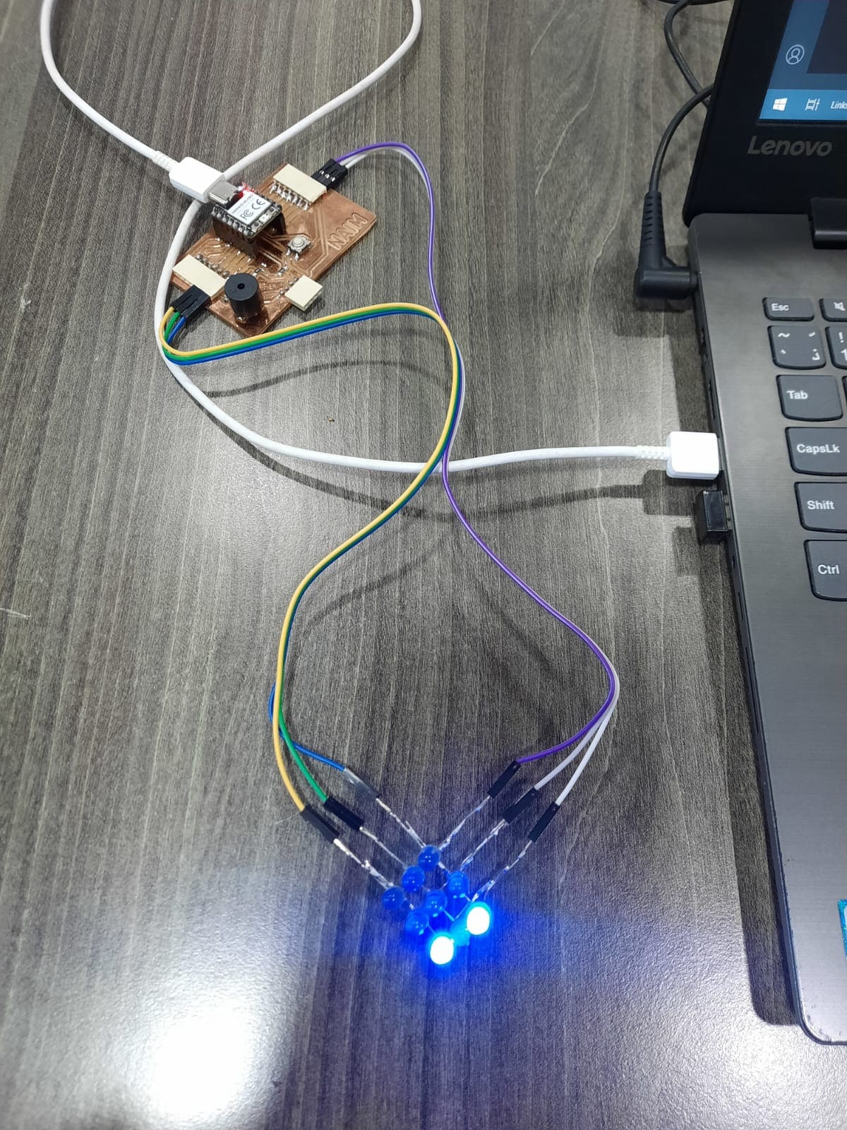
Output Device 2: LED Matrix and Charlieplexing
What is Charlieplexing?
Charlieplexing is a technique used to control multiple LEDs using fewer GPIO pins than the total number of LEDs. It relies on the principle of multiplexing, where LEDs are arranged in a matrix and illuminated selectively by quickly switching between rows and columns.
Charlieplexing allows for controlling multiple LEDs using a minimal number of GPIO pins. In a Charlieplexed LED matrix, each LED is connected between two GPIO pins in a matrix arrangement. By selectively turning on and off pairs of GPIO pins, individual LEDs can be illuminated without interference from others.
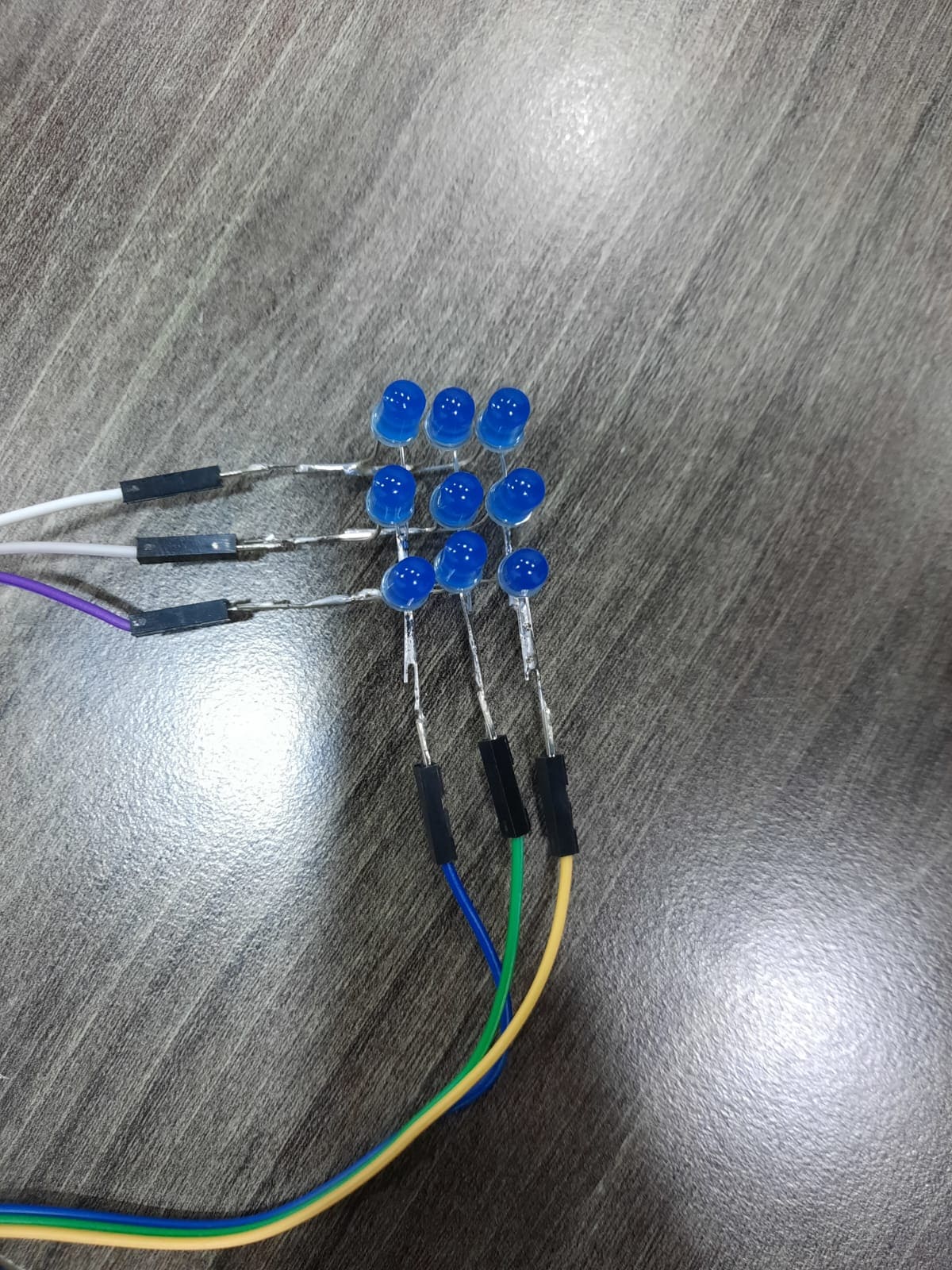
Constructing the LED Matrix
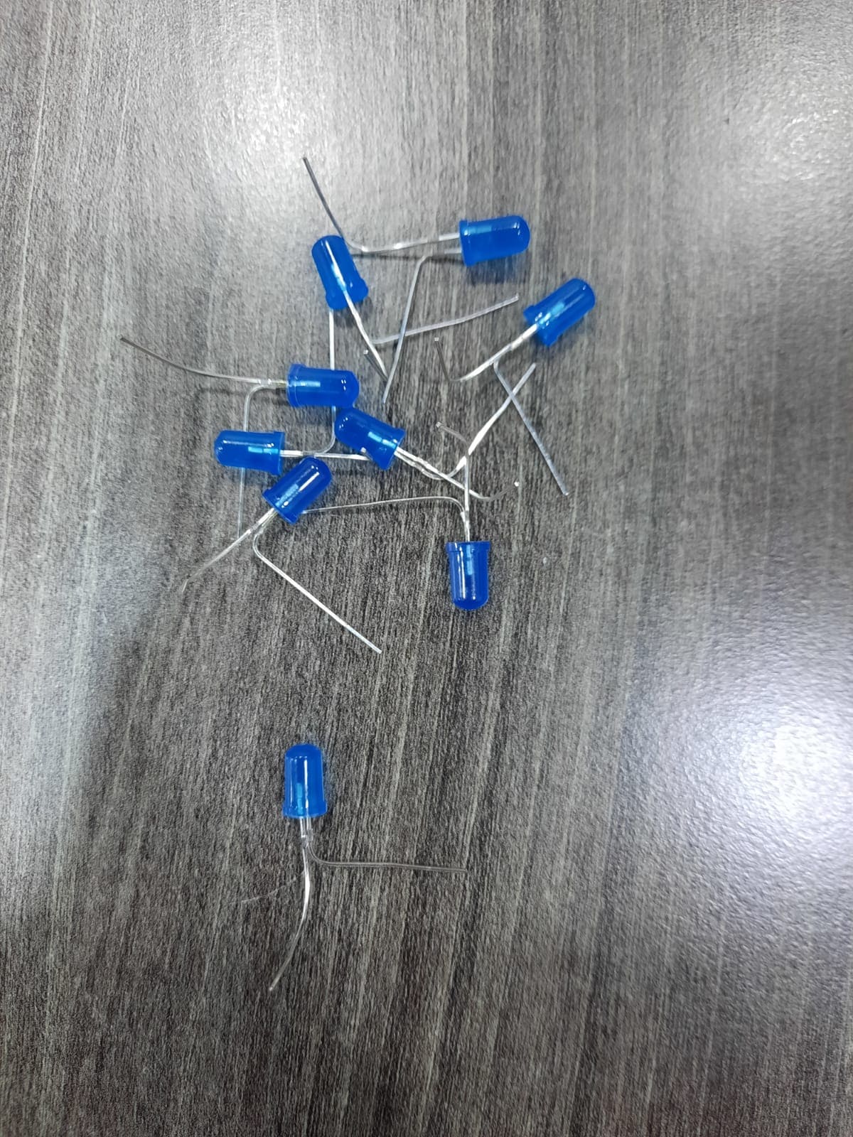
To construct the LED matrix, LEDs are arranged in rows and columns, typically with each LED’s anode connected to a row and cathode connected to a column. Here’s how I constructed the LED matrix:
- Bending LEDs: Initially, I bent all LED cathodes and anodes at 90 degrees and perpendicular to each other to facilitate matrix construction.
- Soldering Rows and Columns: I soldered the LEDs to create rows and columns in the matrix arrangement. Each LED’s anode was connected to a row, and cathode to a column.
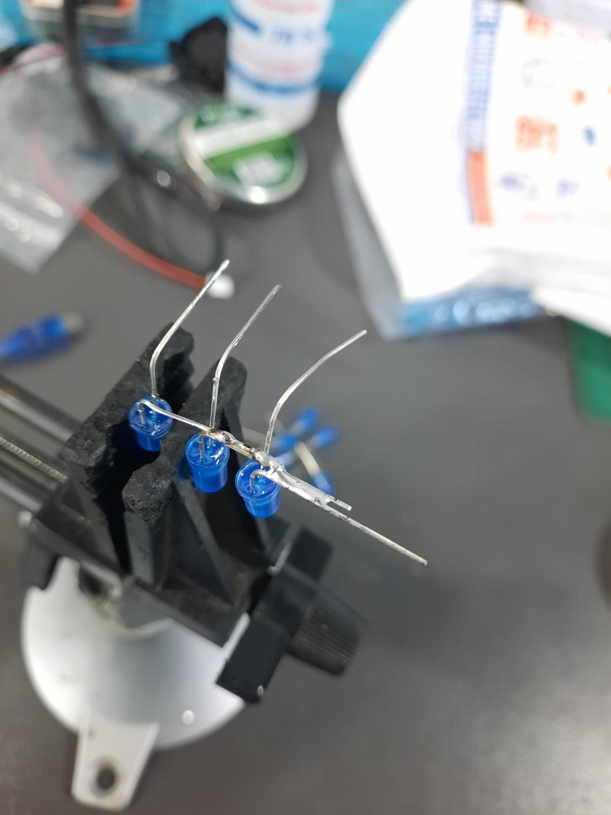
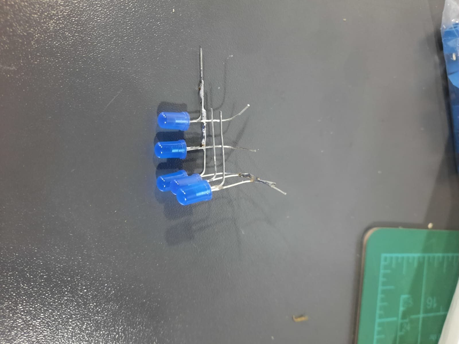
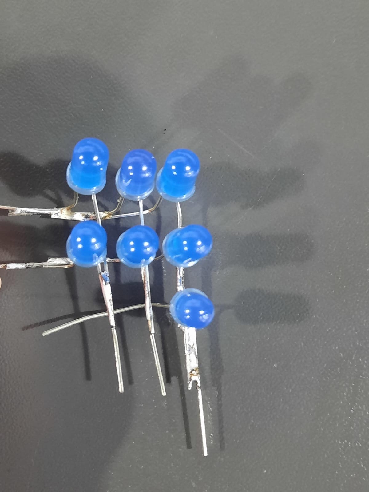
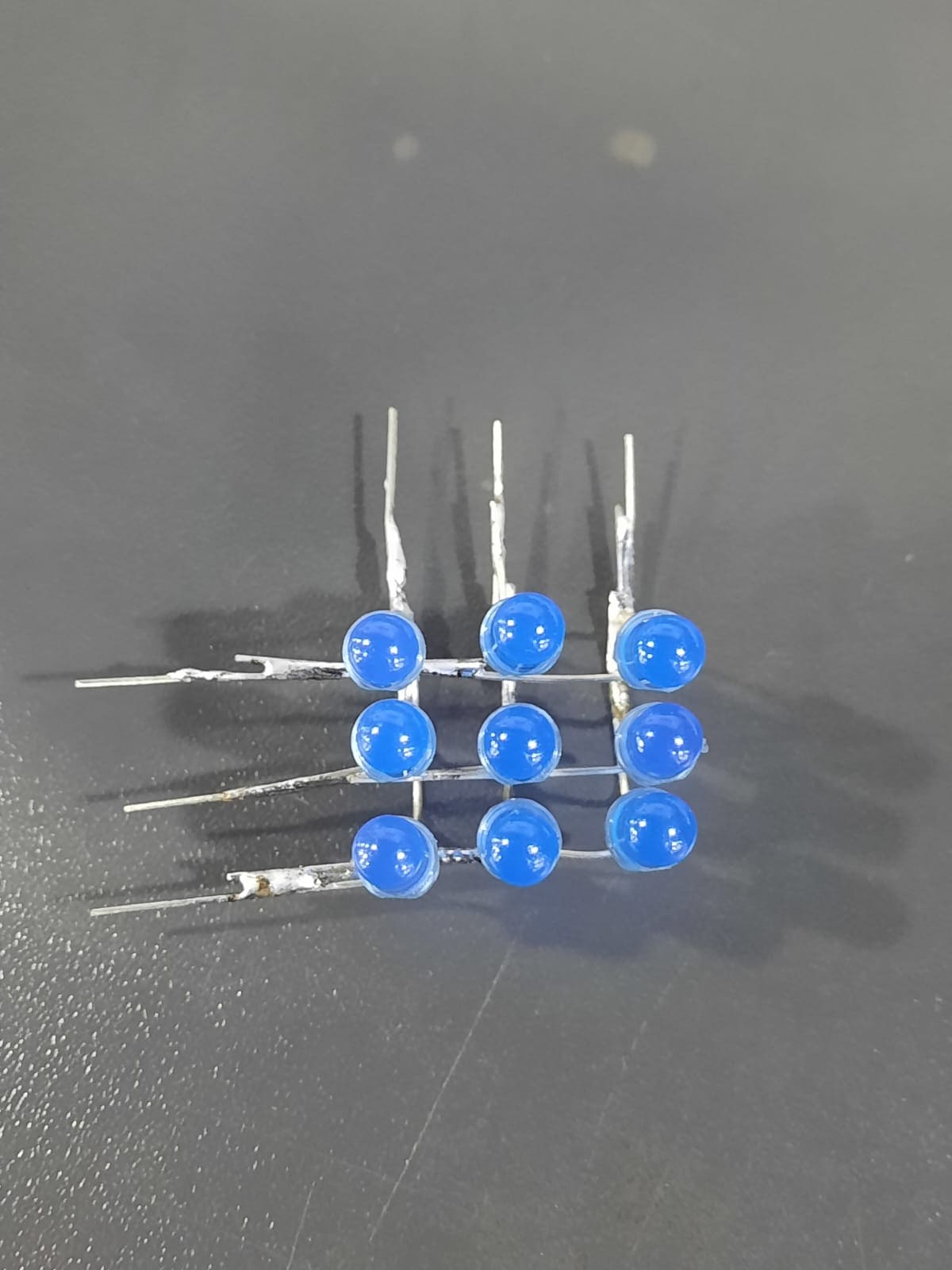
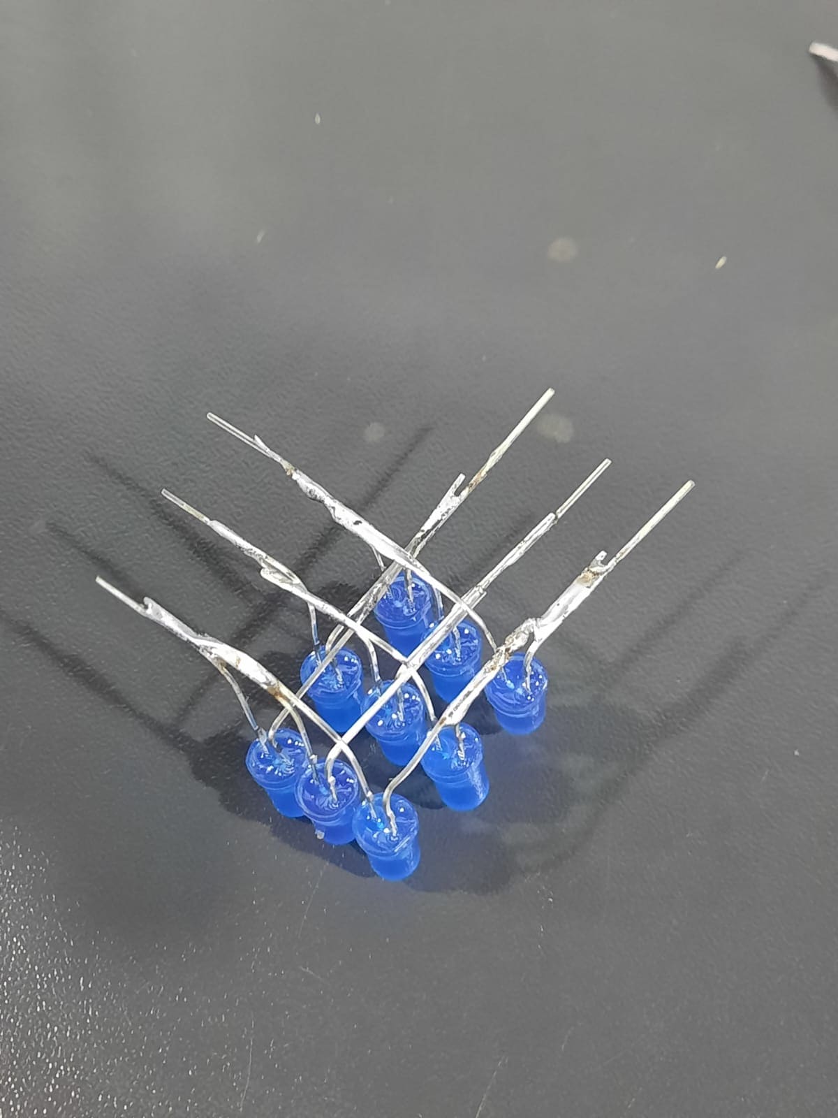
- Adding Wires: Three wires were added for columns and three for rows to connect them to the microcontroller board, allowing control of the LED matrix.
Programming the LED Matrix
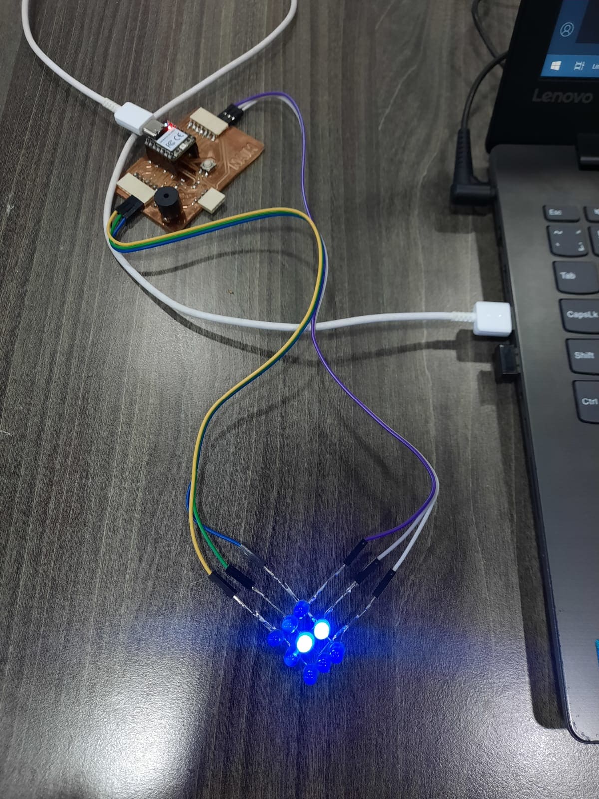
Initially, I programmed the LED matrix to test its functionality. By cycling through rows and columns, I verified that each LED could be turned on and off correctly.
The Code
#define ROW_1_PIN 1
#define ROW_2_PIN 2
#define ROW_3_PIN 4
#define COL_1_PIN 0
#define COL_2_PIN 7
#define COL_3_PIN 6

void setup() {
  // Set the row and column pins as outputs
  pinMode(ROW_1_PIN, OUTPUT);
  pinMode(ROW_2_PIN, OUTPUT);
  pinMode(ROW_3_PIN, OUTPUT);
  pinMode(COL_1_PIN, OUTPUT);
  pinMode(COL_2_PIN, OUTPUT);
  pinMode(COL_3_PIN, OUTPUT);
}

void loop() {
  // Turn on each LED in sequence
  turnOnLED(1, 1); // Turn on LED at row 1, column 1
  delay(500);
  turnOnLED(1, 2); // Turn on LED at row 1, column 2
  delay(500);
  turnOnLED(1, 3); // Turn on LED at row 1, column 3
  delay(500);
  turnOnLED(2, 1); // Turn on LED at row 2, column 1
  delay(500);
  turnOnLED(2, 2); // Turn on LED at row 2, column 2
  delay(500);
  turnOnLED(2, 3); // Turn on LED at row 2, column 3
  delay(500);
  turnOnLED(3, 1); // Turn on LED at row 3, column 1
  delay(500);
  turnOnLED(3, 2); // Turn on LED at row 3, column 2
  delay(500);
  turnOnLED(3, 3); // Turn on LED at row 3, column 3
  delay(500);
}

void turnOnLED(int row, int col) {
  // Turn off all rows and columns
  digitalWrite(ROW_1_PIN, LOW);
  digitalWrite(ROW_2_PIN, LOW);
  digitalWrite(ROW_3_PIN, LOW);
  digitalWrite(COL_1_PIN, LOW);
  digitalWrite(COL_2_PIN, LOW);
  digitalWrite(COL_3_PIN, LOW);

  // Turn on the specified LED
  switch (row) {
    case 1:
      digitalWrite(ROW_1_PIN, HIGH);
      break;
    case 2:
      digitalWrite(ROW_2_PIN, HIGH);
      break;
    case 3:
      digitalWrite(ROW_3_PIN, HIGH);
      break;
  }

  switch (col) {
    case 1:
      digitalWrite(COL_1_PIN, HIGH);
      break;
    case 2:
      digitalWrite(COL_2_PIN, HIGH);
      break;
    case 3:
      digitalWrite(COL_3_PIN, HIGH);
      break;
  }
}
Implementing Serial Control
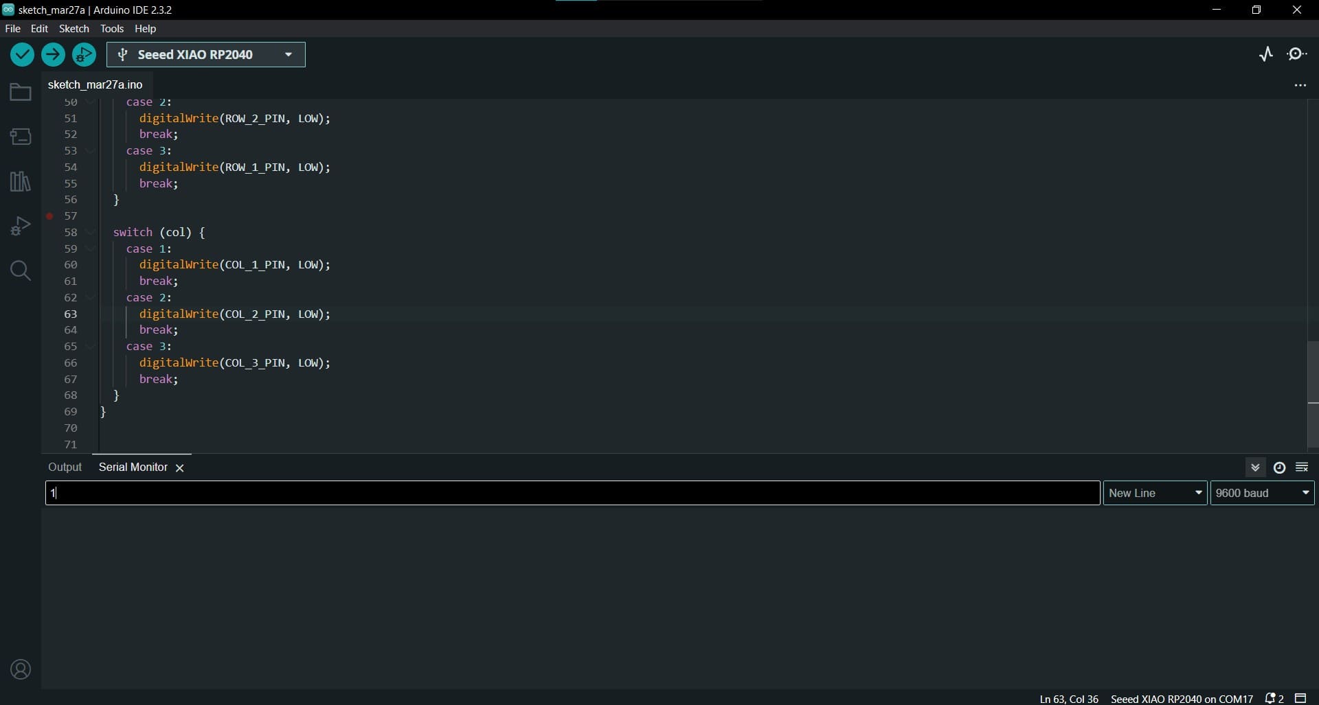
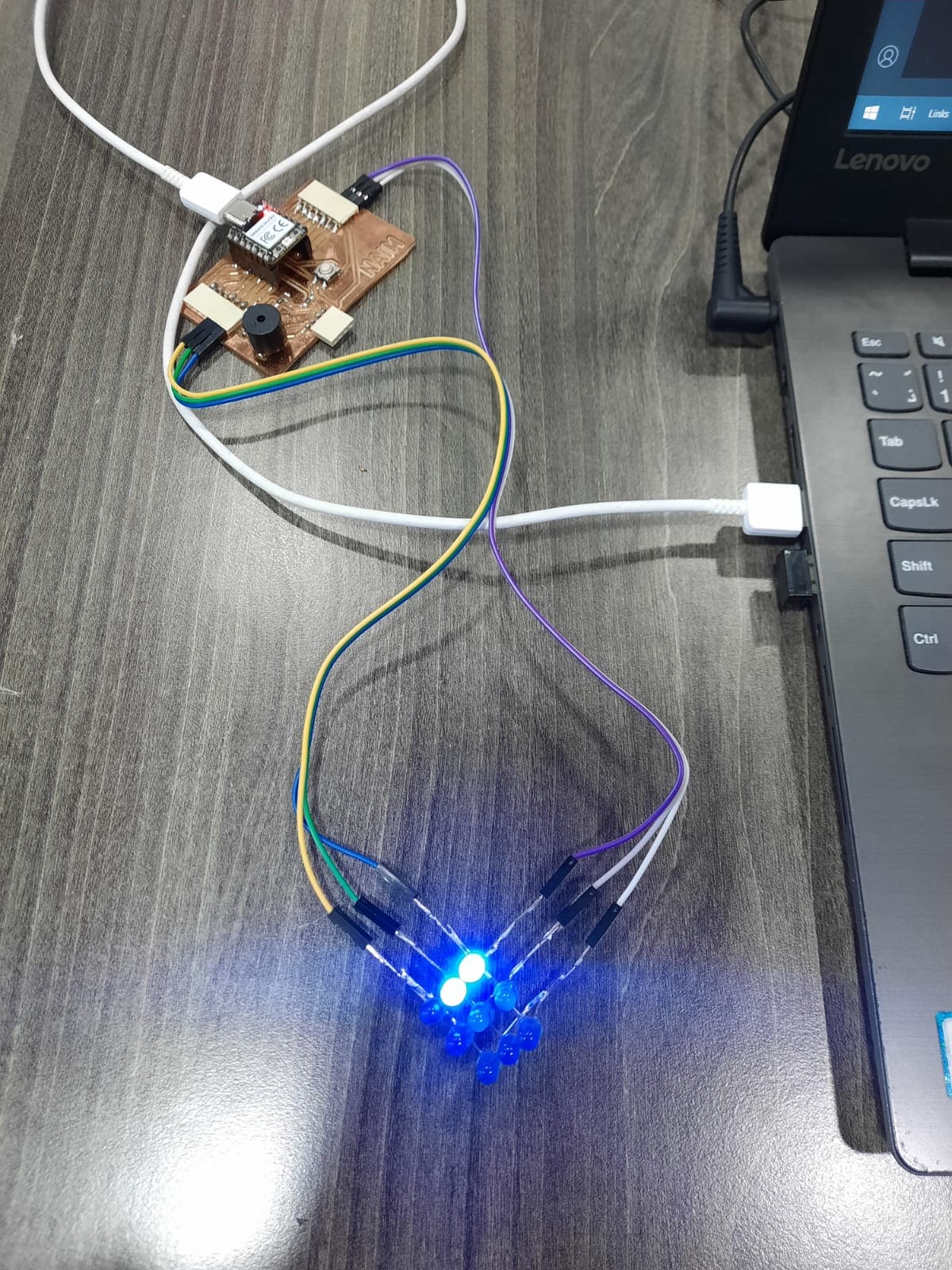
To enhance usability, I modified the code to allow selection of LEDs using the serial monitor. This involved updating the logic to interpret LED numbers entered through the serial monitor and selectively turning off the corresponding row and column pins to illuminate the desired LED.
Charlieplexing offers an efficient way to control large numbers of LEDs with minimal GPIO pins, making it ideal for projects where pin count is limited. Through experimentation and code modification, I successfully implemented Charlieplexing for my LED matrix project, enhancing its functionality and usability.
The Code
#define ROW_1_PIN 1
#define ROW_2_PIN 2
#define ROW_3_PIN 4
#define COL_1_PIN 0
#define COL_2_PIN 7
#define COL_3_PIN 6

void setup() {
  // Set the row and column pins as outputs
  pinMode(ROW_1_PIN, OUTPUT);
  pinMode(ROW_2_PIN, OUTPUT);
  pinMode(ROW_3_PIN, OUTPUT);
  pinMode(COL_1_PIN, OUTPUT);
  pinMode(COL_2_PIN, OUTPUT);
  pinMode(COL_3_PIN, OUTPUT);

  // Initialize serial communication
  Serial.begin(9600);
}

void loop() {
  // Check if data is available in the serial buffer
  if (Serial.available() > 0) {
    // Read the LED number from the serial buffer
    int ledNumber = Serial.parseInt();

    // Turn on the LED corresponding to the entered number
    turnOnLED(ledNumber);
  }
}

void turnOnLED(int ledNumber) {
  // Turn on all rows and columns
  digitalWrite(ROW_1_PIN, HIGH);
  digitalWrite(ROW_2_PIN, HIGH);
  digitalWrite(ROW_3_PIN, HIGH);
  digitalWrite(COL_1_PIN, HIGH);
  digitalWrite(COL_2_PIN, HIGH);
  digitalWrite(COL_3_PIN, HIGH);

  // Determine the row and column for the LED number
  int row = (ledNumber - 1) / 3 + 1; // Calculate row (1 to 3)
  int col = (ledNumber - 1) % 3 + 1; // Calculate column (1 to 3)

  // Turn off the specified LED
  switch (row) {
    case 1:
      digitalWrite(ROW_3_PIN, LOW);
      break;
    case 2:
      digitalWrite(ROW_2_PIN, LOW);
      break;
    case 3:
      digitalWrite(ROW_1_PIN, LOW);
      break;
  }

  switch (col) {
    case 1:
      digitalWrite(COL_1_PIN, LOW);
      break;
    case 2:
      digitalWrite(COL_2_PIN, LOW);
      break;
    case 3:
      digitalWrite(COL_3_PIN, LOW);
      break;
  }
}
Conclusion
In this week, I explored the functionality of two different output devices: an OLED display and an LED matrix using Charlieplexing. Through experimentation and coding, I gained valuable insights into their operation and implementation.
OLED Display
The OLED display provided a versatile means of visual output, allowing me to showcase messages and graphics with ease. By interfacing it with the microcontroller and utilizing the Arduino IDE, I could dynamically control its content and appearance. This experience enhanced my understanding of display technologies and their integration into electronic projects.
LED Matrix and Charlieplexing
The LED matrix, implemented with Charlieplexing, offered a compact solution for displaying multiple LEDs with minimal GPIO pins. By arranging LEDs in rows and columns and selectively controlling their illumination, I could create visually appealing patterns and animations. This project not only deepened my understanding of multiplexing techniques but also honed my coding skills in managing complex LED configurations.
Overall Reflection
Working with both the OLED display and LED matrix provided valuable hands-on experience in integrating output devices into electronic projects. From the simplicity of displaying text on the OLED to the intricacies of managing a matrix of LEDs, I encountered challenges that fostered problem-solving and innovation. This project showed the importance of adaptability and creativity in electronics design, reinforcing my passion for exploring new technologies and pushing the boundaries of what’s possible.
By combining the versatility of the OLED display with the efficiency of Charlieplexing in the LED matrix, I gained a comprehensive understanding of output device technologies and their practical applications. Moving forward, I’m excited to leverage these insights in future projects and continue my journey of exploration and discovery in electronics design.