5. 3D Scanning and Printing
This week, we’re exploring 3D scanning and printing, key aspects of digital fabrication. We’ll learn about scanning techniques, using 3D printers, and optimizing designs and materials. Through hands-on practice, we’ll understand the strengths and limitations of these technologies and improve our skills in creating detailed models. Join us as we delve into the world of 3D scanning and printing in digital fabrication.
Learning Outcomes:
- Identify the advantages and limitations of 3D printing
- Apply design methods and production processes to show your understanding of 3D printing.
- Demonstrate how scanning technology can be used to digitize object(s)
Summary of Group Assignment: Testing Ultimaker S5 3D Printers
The group assignment focused on testing the design rules for Ultimaker S5 3D printers and documenting the process. Here’s a summary of the key points:
-
Ultimaker S5 Specifications: The Ultimaker S5 boasts impressive specifications, including a large build volume, dual extrusion capability, heated print bed, and compatibility with various filament materials.
-
Safety Measures: Safety measures for using the Ultimaker S5 include ventilation, fire safety precautions, secure power supply, proper material handling, and regular maintenance.
-
Design Rule Testing: Design rule testing involved using a 3D design test to assess overhang, warping, size accuracy, bridge test, fine details, and general accuracy.
-
Ultimaker Cura Slicer: Ultimaker Cura slicer software was used for slicing, offering user-friendly controls, a powerful slicing engine, extensive material profiles, customization options, and integration with the Ultimaker ecosystem.
-
Printing Process: The printing process with the Ultimaker S5 was outlined, including preparing the printer, bed preparation, filament loading, selecting and loading the print file, calibrating the printer, starting the print, and post-processing.
-
Test Results: Test results showed good performance in overhang and bridge tests, but minor inconsistencies in fine details highlighted the importance of meticulous design preparation.
-
Overall Assessment: The Ultimaker S5 proved to be a reliable and versatile 3D printer capable of producing high-quality prints with careful adjustments and thoughtful design considerations.
This summary encapsulates the group’s experience with the Ultimaker S5 and provides insights into its capabilities and considerations for achieving optimal results.
Individual Assignemnt:
A. 3D Scanning Using Polycam
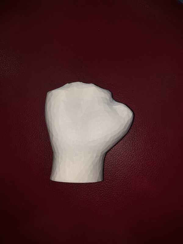
Description of the Hand Scanned with Polycam: For the individual assignment, I initiated the 3D scanning process by using Polycam, a mobile scanning application. With Polycam, I captured a detailed 3D scan of a hand. This process involved carefully positioning mthe hand within the camera frame of my mobile device and allowing Polycam to capture multiple angles to generate a comprehensive 3D model.
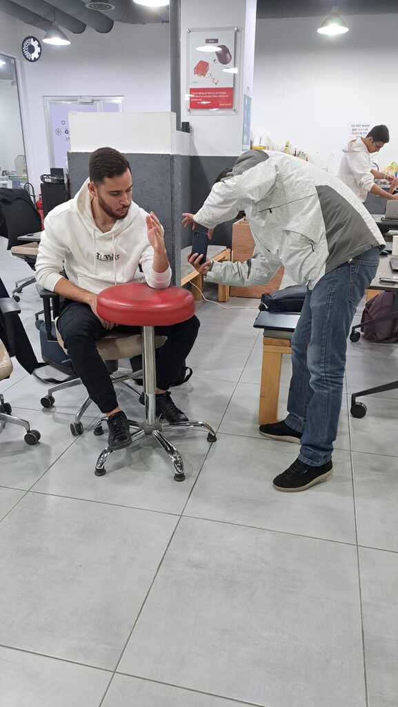
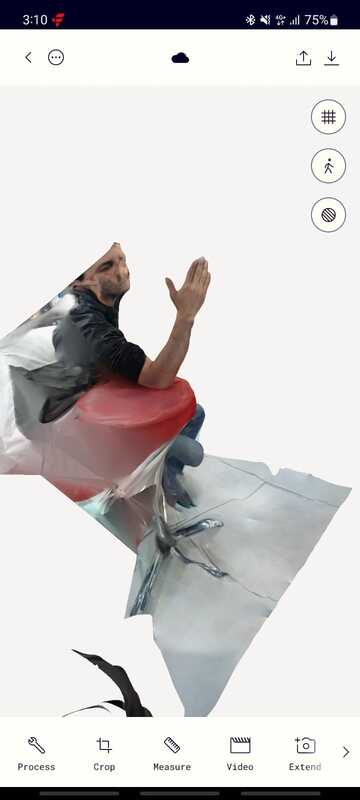
The Polycam scanning process yielded impressive results, showcasing both the ease of use and the quality of the scan. Polycam’s intuitive interface made the scanning process remarkably user-friendly, allowing for quick and efficient capture of detailed 3D models. Despite its simplicity, the scan quality remains remarkably high, capturing intricate details with clarity and precision. Overall, Polycam proves to be a valuable tool for 3D scanning, combining accessibility with excellent results.
B. Mesh Editing Using Meshmixer
- Explanation of the Import Process Using Meshmixer: After capturing the hand model with Polycam, I proceeded to import the resulting STL file into Meshmixer for further editing and refinement. Meshmixer served as a versatile tool for mesh editing, enabling me to enhance the quality and detail of the scanned model.
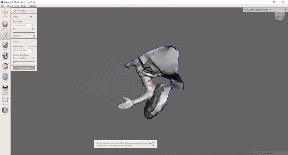
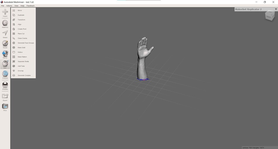
- Documentation of the Meshmixer Workflow: In Meshmixer, I embarked on a comprehensive workflow to edit and refine the scanned hand model. This involved a series of steps, including smoothing surfaces, and adjusting geometry to achieve a more accurate representation of my hand in the digital domain. Meshmixer’s intuitive interface and powerful editing tools facilitated the workflow, allowing me to iterate on the design and achieve the desired level of detail and precision.

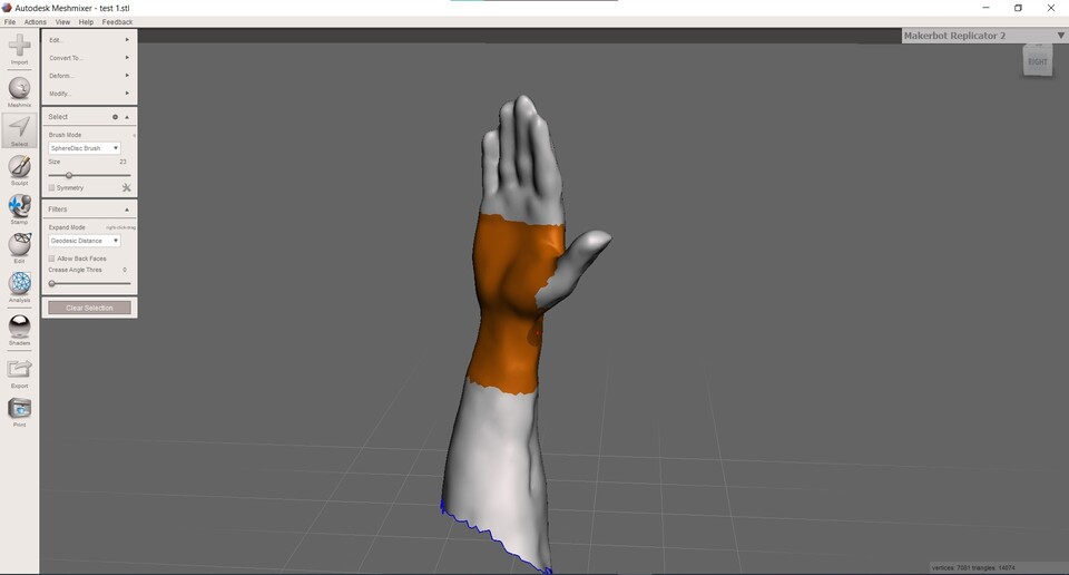
-
Remove Extraneous Geometry: Identify and delete any unnecessary geometry that is not relevant to the splint design, using the lasso selection tool for precise removal.
-
Scale the Model: Adjust the scale of the hand model to the correct dimensions, ensuring a snug fit for the splint.
-
Define Splinting Area: Highlight and select the specific region of the hand that requires splinting, using precise selection tools.
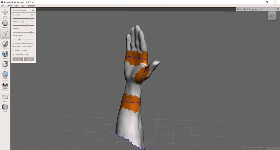
-
Smooth Boundary: Smooth the boundary of the selected area to ensure a comfortable fit and a seamless transition between the hand and the splint.
-
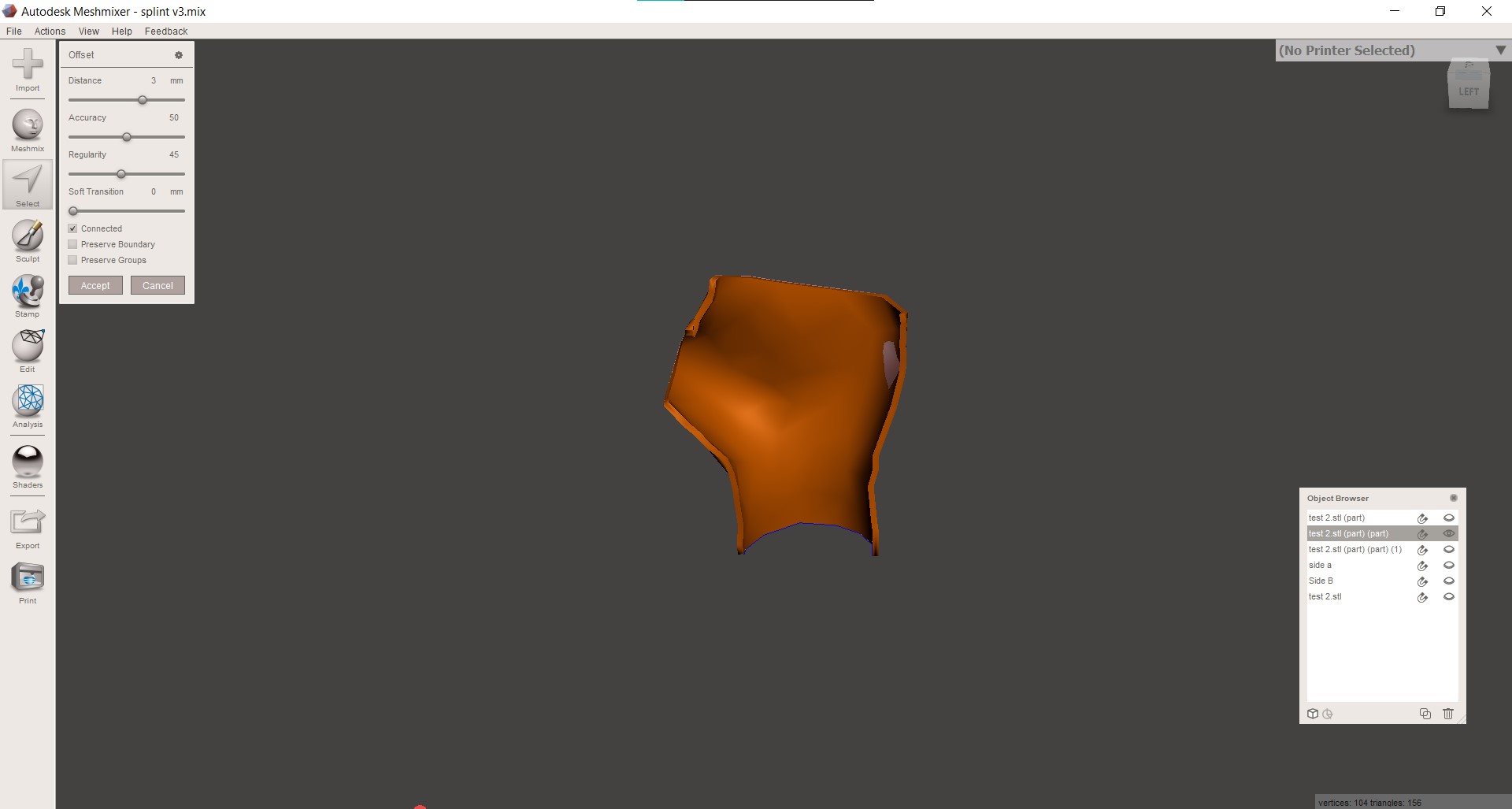
Apply Offset for Surface: Use the offset function to create a surface with a 1mm offset, providing adequate spacing between the hand and the interior surface of the splint.
-
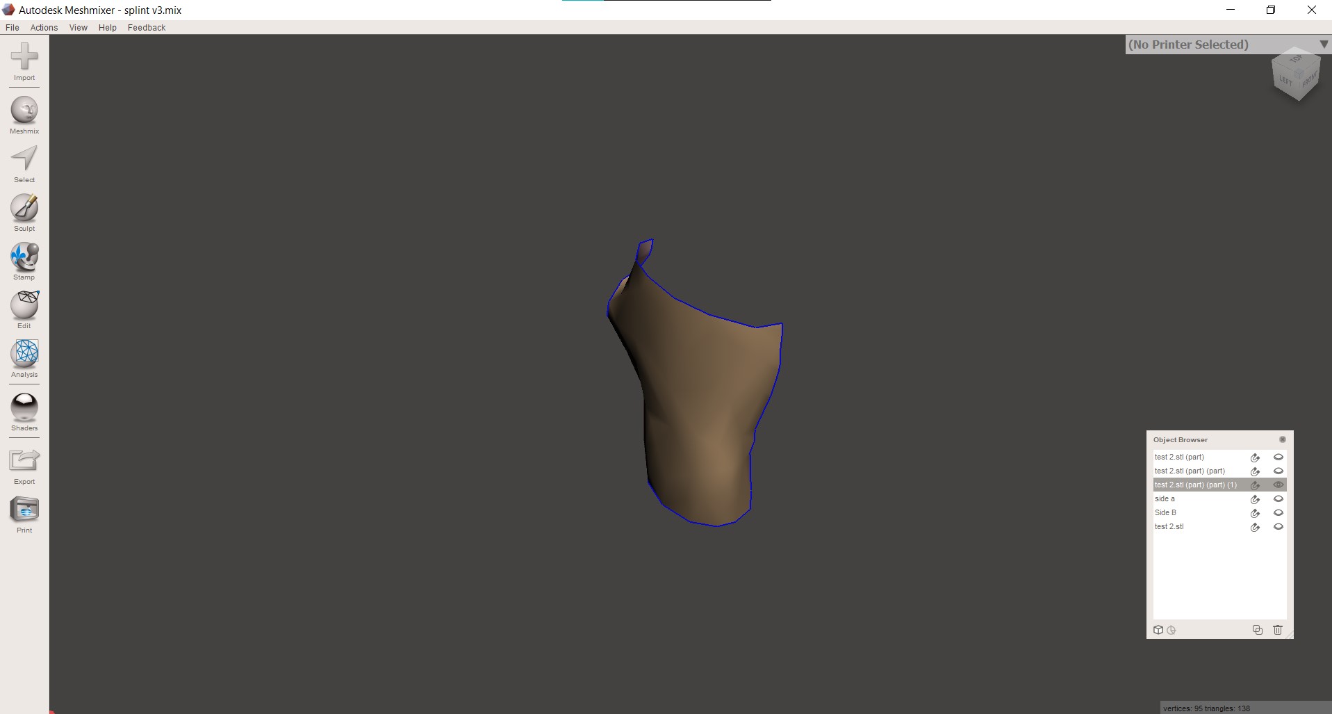
Isolate the Splinting Area: Isolate the selected splinting area to focus exclusively on the design of the splint.
-
Apply Outward Offset: Apply an outward offset of 3mm to the isolated splinting surface to achieve the desired thickness of the splint.
-
Smooth Edges: Select and smooth the edges of the splinting surface to enhance the aesthetic and comfort of the splint.
-
Mesh Reduction: Apply a mesh reduction technique to optimize the mesh, reducing unnecessary complexity while maintaining structural integrity.
Through the 3D scanning and mesh editing process, I gained valuable insights into the capabilities and limitations of mobile scanning applications and mesh editing software. These experiences equipped me with the skills and knowledge necessary to effectively capture and manipulate 3D models for various applications and projects.
C. Printing using Ultimaker S5
To proceed with printing the splint designed in Meshmixer on the Ultimaker S5, the following steps were taken:
-
Exporting the STL File: The designed splint model was exported as an STL file from Meshmixer. This involved ensuring the correct file format and export settings to maintain accuracy and compatibility.
-
Importing into Cura: The exported STL file was imported into Cura, the slicing software compatible with the Ultimaker S5. Within Cura, print settings such as layer height, infill density, and support structures were adjusted according to the requirements of the splint design.
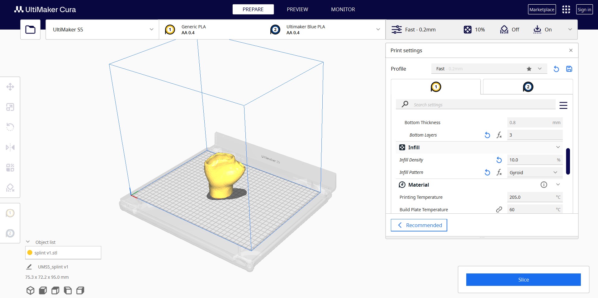
- Slicing the Model: After configuring the print settings , the STL model was sliced to generate G-code instructions for the Ultimaker S5 printer. This involved previewing the print layers and ensuring the accuracy of the slicing process.
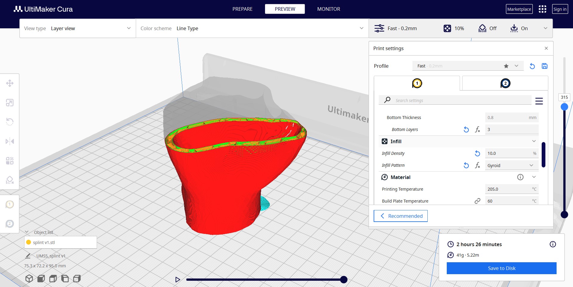
Print Settings Used: - Layer Height: 0.2mm - Infill Density: 10% - Support Structures: None (As the splint design did not require supports) - Print Temperature: 200°C (for PLA filament) - Print Speed: 60 mm/s - Build Plate Adhesion Type: Brim - Build Plate Temperature: 60°C
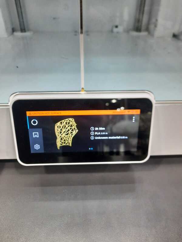
- Transferring G-code to Printer: Once the G-code file was generated, it was transferred to the Ultimaker S5 printer for printing. The printer was prepared by loading PLA filament and ensuring proper calibration.
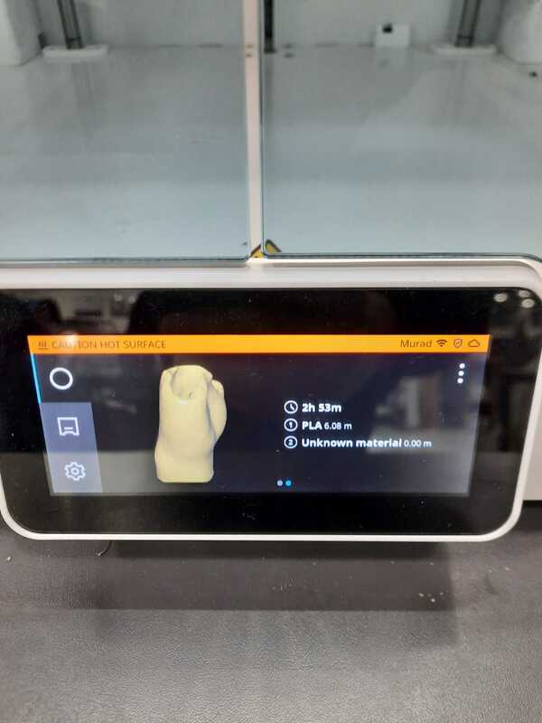
- Initiating Printing: With the G-code file loaded, the printing process was initiated through the printer’s interface. The progress of the print job was monitored closely to address any issues or errors that may arise during printing.
- Post-Processing: After the printing was completed, the splint was carefully removed from the print bed. It did not need any post processing as it was printed with no supports, only the brim was removed easily.
By following these steps, the process of exporting, slicing, and printing the splint on the Ultimaker S5 was successfully completed, utilizing PLA filament for the printing material.
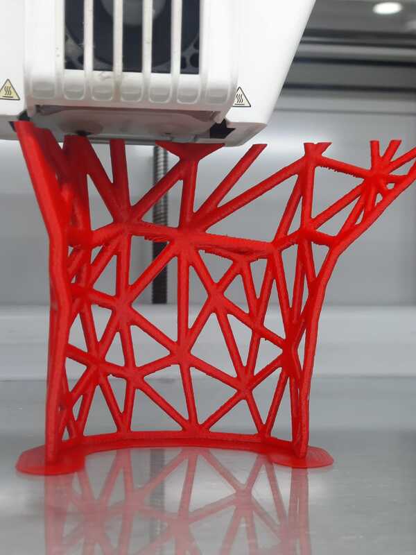
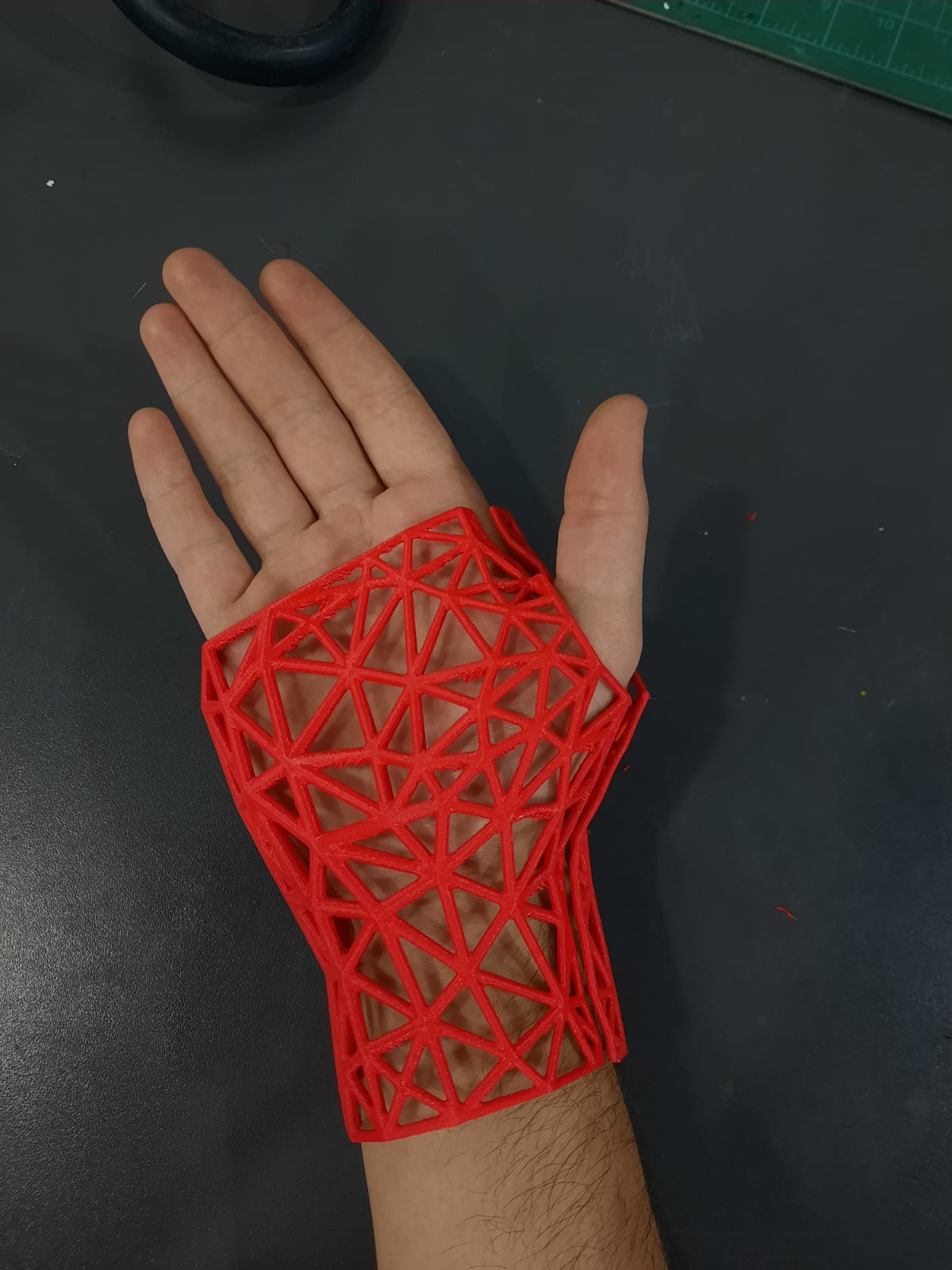
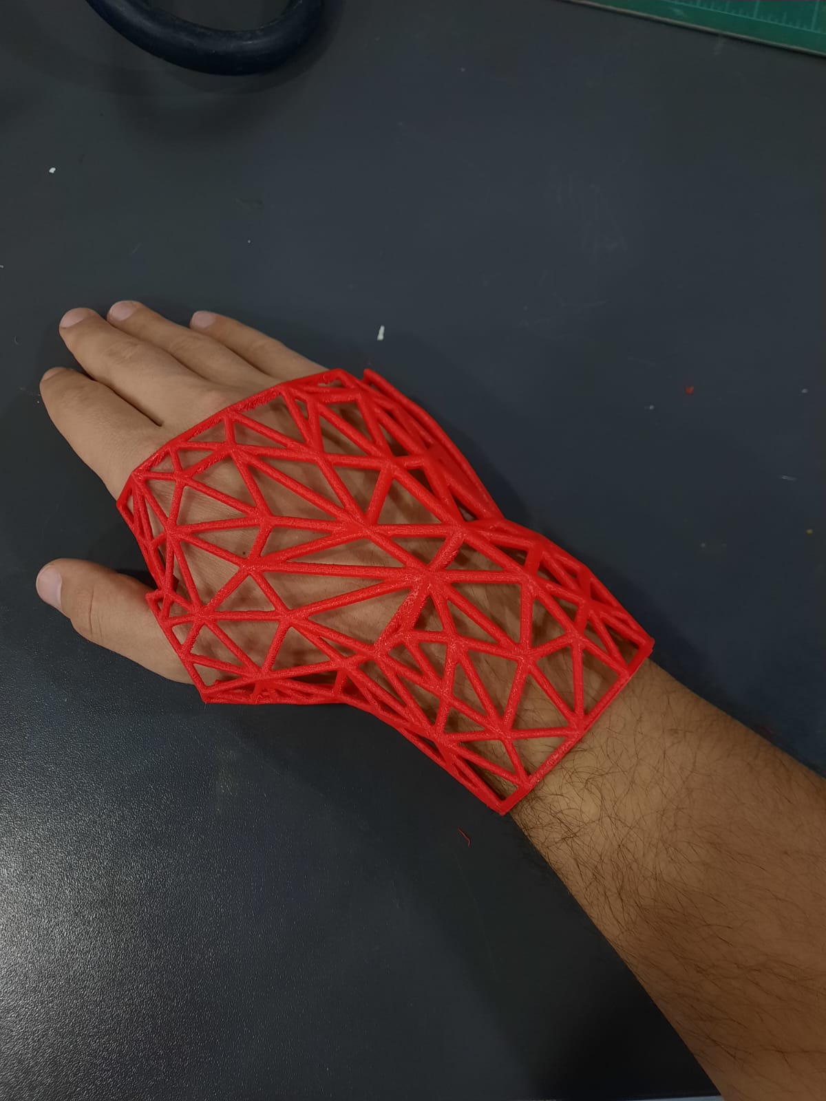
D. Redesigning and Iterating
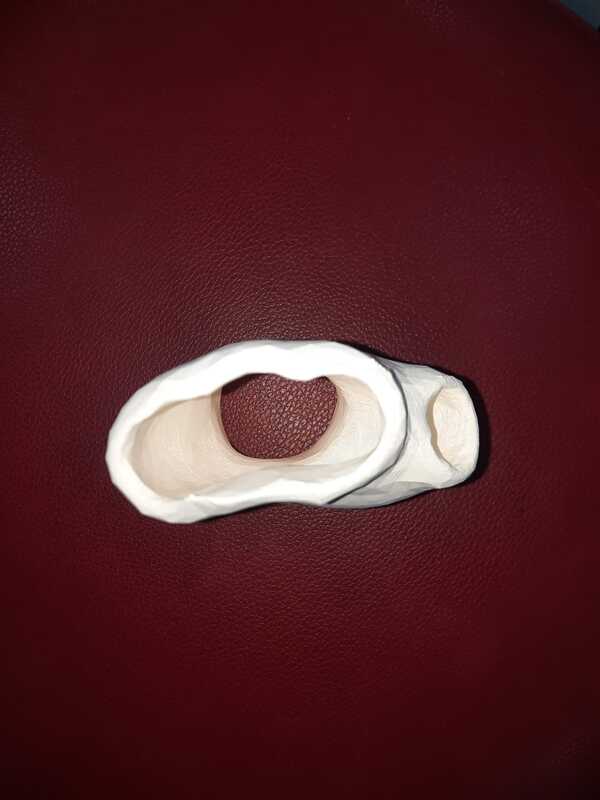
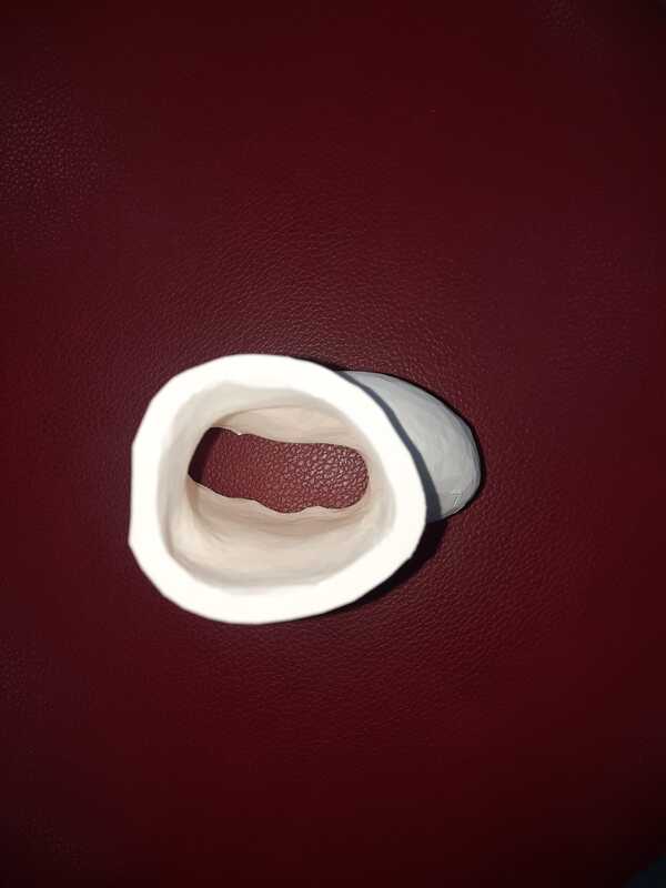
In Meshmixer, I embarked on creating an alternative design for the splint, incorporating a breathable pattern while splitting the splint into two halves for enhanced flexibility and comfort. Here’s a detailed breakdown of the design process:
- Plane Cut for Splint Shape: I Utilized the plane cut tool to achieve the required shape for the splint, ensuring proper fit and coverage over the affected area of the hand.
- Offset from Surface: I applied an offset from the surface to create a small gap between the splint and the hand, allowing for comfortable wear and accommodating any swelling or movement.
- Splitting the Splint into Two Halves: I opted to split the splint design into two halves to enhance adaptability and ease of application, facilitating adjustments without compromising effectiveness.
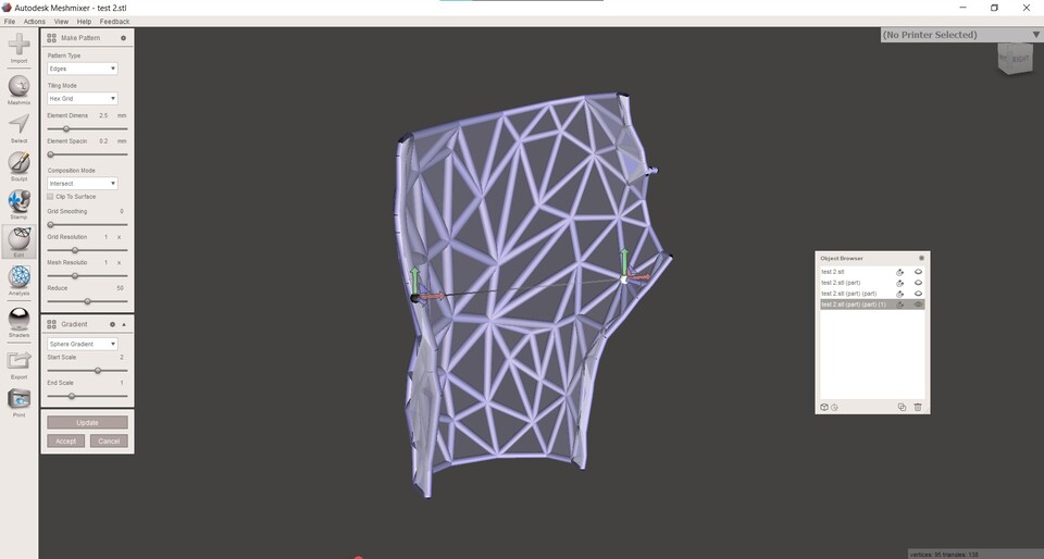
- Remeshing for Proper Mesh Density: I remeshed the two halves of the splint to achieve proper mesh density, ensuring structural integrity and optimal printing results.
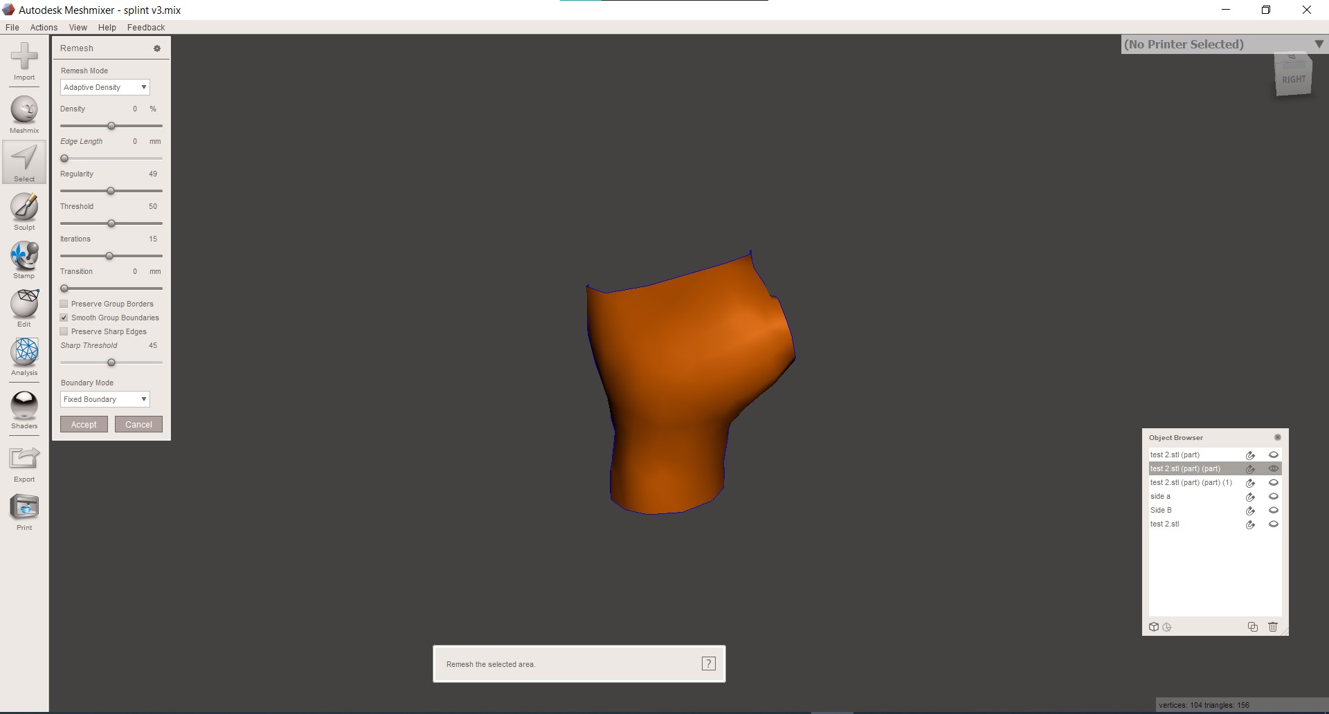
- Editing Pattern for Breathability: i utilized Meshmixer’s edit pattern feature to adjust settings and create a breathable pattern that promotes airflow while maintaining strength and support.
- Exporting as STL Files: I exported the two halves of the splint as STL files, ensuring compatibility with slicing software and 3D printing.
This innovative approach to splint design prioritized functionality and comfort, showcasing the versatility of Meshmixer in creating intricate and customizable 3D models for additive manufacturing applications.
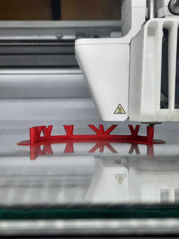
- Slicing and Printing the Design: With the STL file ready, I proceeded to slice the design using Cura Ultimaker slicing software. After configuring the print settings, such as layer height and infill density, I initiated the printing process using PLA filament on the Ultimaker S5 printer.
Print Settings Used: - Layer Height: 0.2mm - Infill Density: 10% - Support Structures: None - Print Temperature: 200°C (for PLA filament) - Print Speed: 60 mm/s - Build Plate Adhesion Type: Brim - Build Plate Temperature: 60°C
E. Importance of Utilizing 3D Printing for Splint Creation
Utilizing 3D printing technology for creating splints offers several significant advantages over traditional subtractive manufacturing methods. Here’s why 3D printing is crucial for splint production and why it cannot be easily achieved subtractively:
-
Customization and Personalization: Every individual’s anatomy is unique, and splints often need to be tailored to fit specific shapes and sizes. 3D printing allows for the creation of highly customized splints that precisely conform to the patient’s anatomy, providing optimal support and comfort. Traditional subtractive methods lack the precision and flexibility required to produce such customized solutions efficiently.
-
Complex Geometries: Splints may require intricate designs and complex geometries to address specific medical needs or conditions. 3D printing enables the fabrication of splints with intricate structures, patterns, and internal supports that cannot be easily achieved through subtractive manufacturing processes. This capability allows designers to incorporate features such as breathable patterns, ergonomic contours, and lightweight structures to enhance patient comfort and usability.
-
Rapid Prototyping and Iterative Design: 3D printing facilitates rapid prototyping and iterative design processes, allowing designers and medical professionals to quickly iterate and refine splint designs based on patient feedback and clinical requirements. This iterative approach to design optimization is essential for developing effective and patient-centric splint solutions. In contrast, subtractive manufacturing methods may require time-consuming and costly rework to implement design modifications.
-
Material Efficiency: 3D printing minimizes material waste by only depositing material where it is needed, optimizing material usage and reducing overall production costs. This efficiency is particularly advantageous for producing custom splints, where material waste must be minimized to ensure cost-effectiveness and sustainability. Subtractive manufacturing processes, on the other hand, often generate significant material waste during the machining process.
-
Integration of Functional Features: 3D printing allows for the integration of functional features directly into the splint design, such as adjustable straps, ventilation channels, and patient-specific orthotic inserts. These integrated features enhance the functionality and usability of the splint, providing patients with a more comfortable and tailored therapeutic solution.
In summary, 3D printing offers many capabilities for the design and production of customized splints that meet the unique needs of individual patients. Its ability to create complex geometries, facilitate rapid prototyping, optimize material usage, and integrate functional features makes 3D printing indispensable for modern orthotic and prosthetic applications.
F. Using the Spider Handheld 3D Scanner:
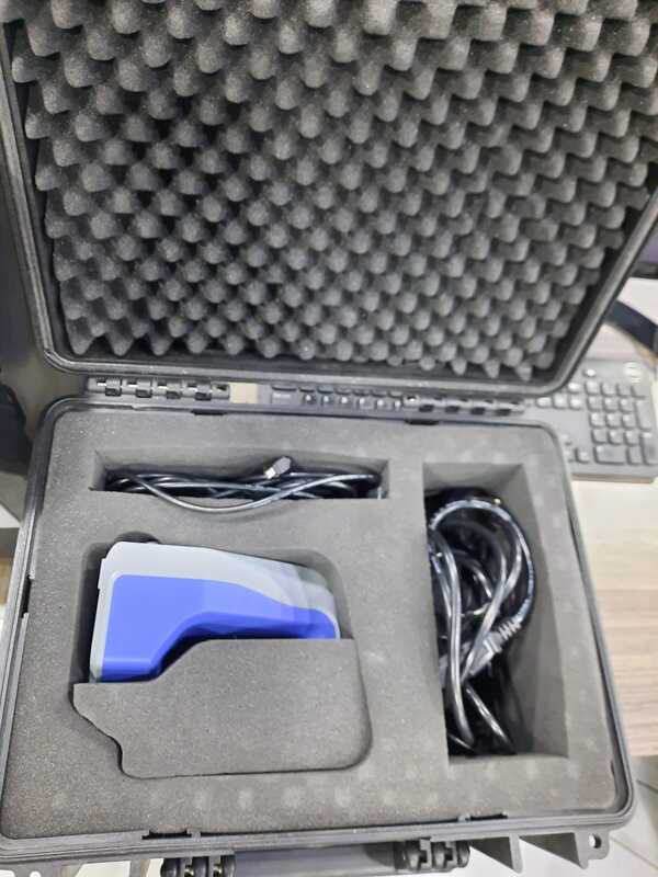
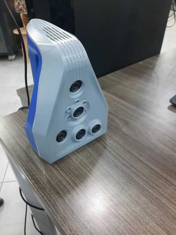
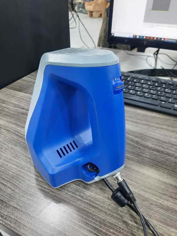
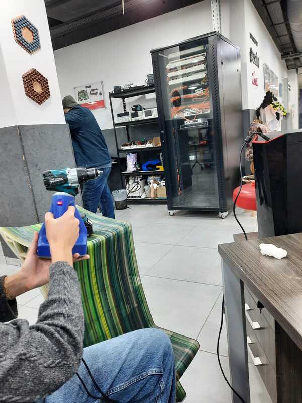
I was introduced to the Spider Handheld 3D scanner by Lina. She demonstrated how to operate the scanner and provided guidance on its usage. As part of the demonstration, Lina created a test scan and successfully scanned a cordless drill, showcasing the scanner’s capabilities.
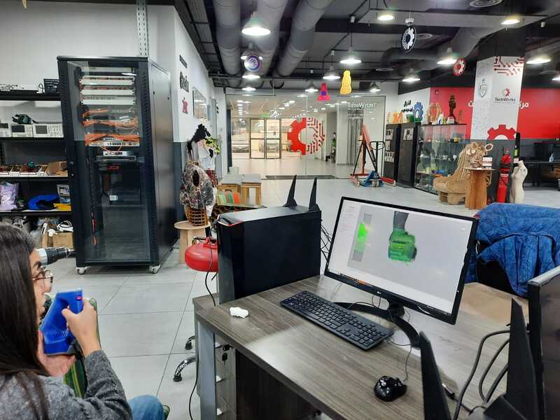
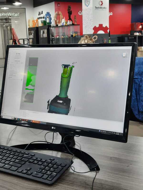
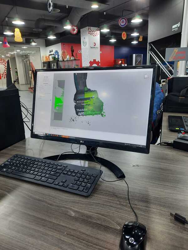
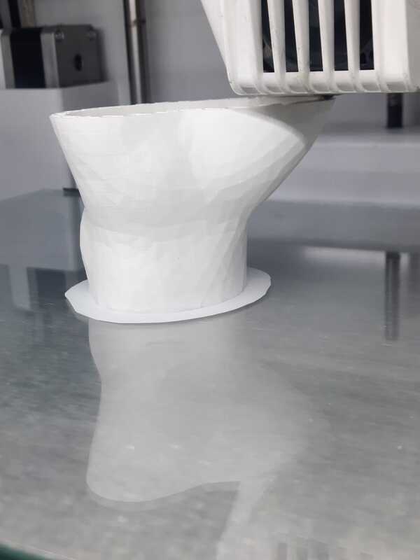
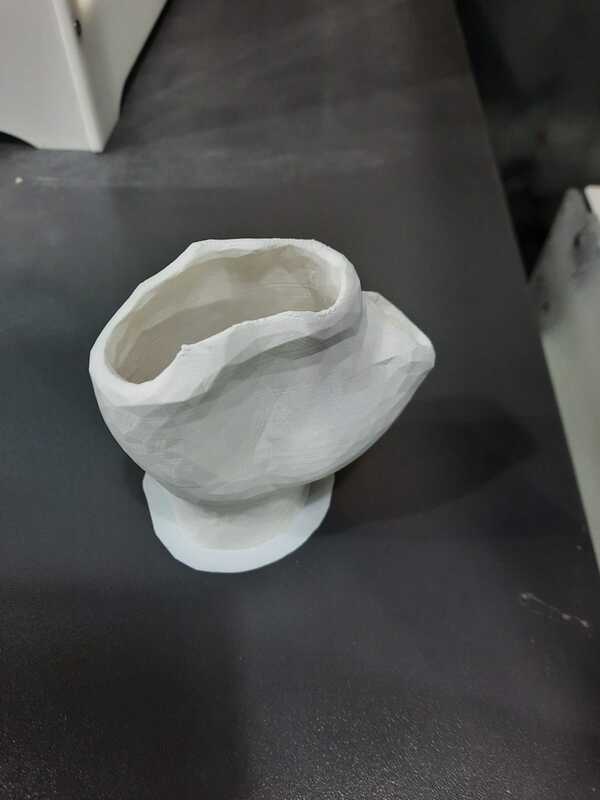
After familiarizing myself with the scanner, I decided to use it to scan a vase that was created using the clay 3D printer. I carefully scanned the vase from various angles to capture its intricate details and contours. Once the scanning process was complete, I obtained multiple scans of the vase from different perspectives.
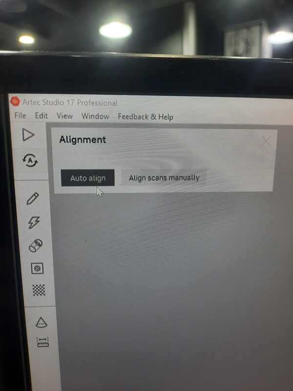
Next, I used the scanning software and proceeded to clean and refine the scans. This involved removing any unwanted artifacts or noise present in the scans to ensure accuracy and clarity. Additionally, I utilized the auto-align feature within the software to align the different scans seamlessly, ensuring proper registration and alignment of the scanned data.
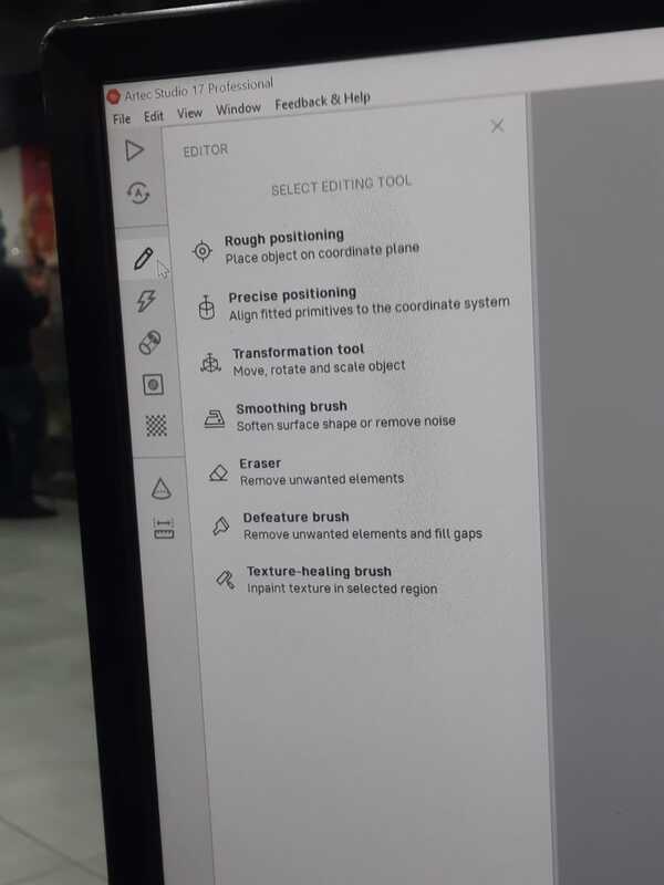
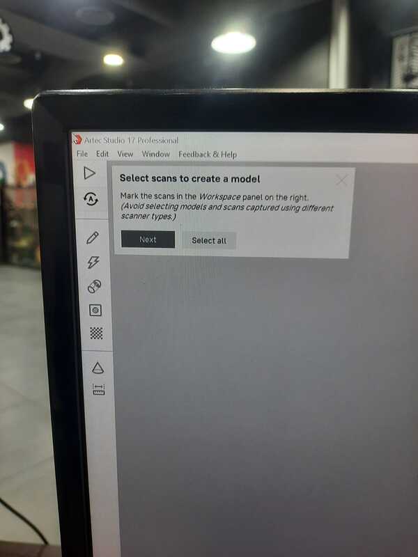
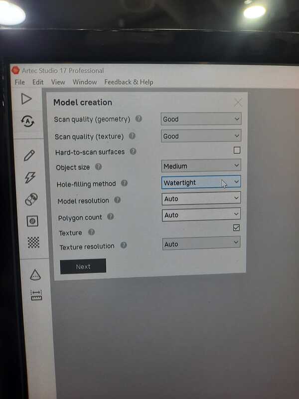
Upon successful alignment, the scanning software generated a watertight mesh representing the scanned object. This mesh accurately captured the geometry and surface details of the vase. Finally, I exported the mesh as an STL file, making it compatible with 3D printing software for further processing and printing.
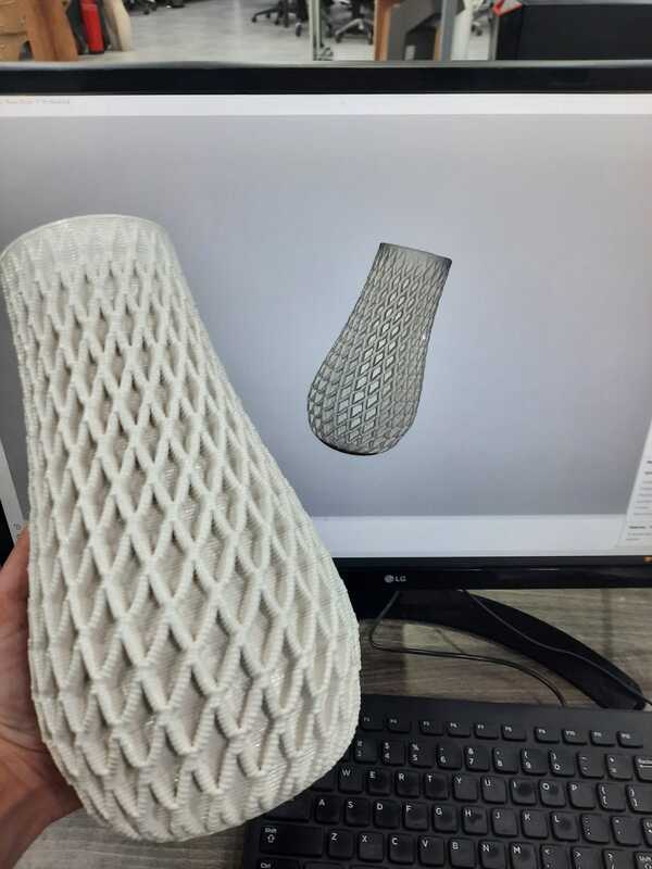
Using the Artec Spider scanner presented a more intricate and challenging process compared to the Polycam. The Artec Spider scanner requires a deeper understanding of scanning techniques and settings, resulting in a steeper learning curve. Its advanced features and capabilities offer a wide range of customization options, allowing for precise control over the scanning process. However, mastering these features may require additional time and practice. Despite the initial complexity, the Artec Spider scanner excels in capturing fine details and intricate surfaces, making it a powerful tool for high-resolution 3D scanning tasks.
Conclusion
Reflection on 3D Scanning:
In contrast to the simplicity and user-friendliness of Polycam, I also experimented with the Artic Spider 3D scanner. While the Artic Spider offers advanced capabilities, it comes with a steeper learning curve and requires more expertise to operate effectively. Here are some observations from my experience:
-
Complex Operation: The Artic Spider 3D scanner involves a more intricate setup and calibration process compared to Polycam. It requires a deeper understanding of scanning principles and techniques to achieve accurate results.
-
Advanced Features: The Artic Spider offers advanced features such as higher precision and resolution, making it suitable for capturing detailed scans of complex objects. However, mastering these features requires time and practice.
-
Learning Curve: Due to its complexity, using the Artic Spider involves a steeper learning curve. Users may need to invest additional time in training and experimentation to become proficient in operating the scanner effectively.
-
Technical Challenges: The Artic Spider may encounter technical challenges such as alignment errors, calibration issues, and data processing complexities. Addressing these challenges requires troubleshooting skills and technical knowledge.
-
Specialized Applications: While Polycam is suitable for quick and simple scans, the Artic Spider is better suited for specialized applications that demand high precision and detailed scanning, such as industrial design, engineering, and research.
Overall, while the Artic Spider 3D scanner offers advanced capabilities for capturing detailed scans, its complexity and learning curve make it better suited for experienced users or specialized applications.
Reflection on 3D Printing
Throughout the completion of this week’s assignment on 3D scanning and printing, I’ve gained valuable insights into the capabilities and limitations of this transformative technology. Here are some reflections on the advantages and limitations of 3D printing:
Advantages:
-
Design Flexibility: 3D printing allows for the creation of complex geometries and intricate designs that are challenging or impossible to achieve with traditional manufacturing methods. This flexibility enables the production of highly customized and optimized parts tailored to specific applications.
-
Rapid Prototyping: With 3D printing, prototypes can be quickly produced from digital designs, accelerating the product development cycle. This rapid prototyping capability allows designers and engineers to iterate on designs rapidly, test concepts, and validate functionality before committing to full-scale production.
-
Customization and Personalization: 3D printing facilitates the customization and personalization of products, enabling individualized solutions tailored to end-users’ unique needs and preferences. From personalized medical implants to consumer goods, 3D printing offers new and unique opportunities for customization.
Limitations:
-
Limited Material Properties: While 3D printing supports a wide range of materials, each material has inherent limitations in terms of mechanical properties, surface finish, and durability. For example, some 3D printed plastics may lack the strength or heat resistance required for certain applications compared to traditional engineering plastics.
-
Print Speed and Production Volume: 3D printing can be relatively slow compared to traditional manufacturing methods, especially for large or complex parts. Print speed depends on factors such as layer height, infill density, and part geometry. Additionally, the production volume of 3D printers may be limited compared to mass production techniques, making it less suitable for high-volume manufacturing.
In conclusion, while 3D printing offers numerous advantages such as design flexibility, rapid prototyping, and customization, it also presents challenges such as material limitations, print speed, and dimensional accuracy. By understanding these advantages and limitations, I am better equipped to leverage 3D printing technology effectively in future projects and endeavors.