My Final Project example
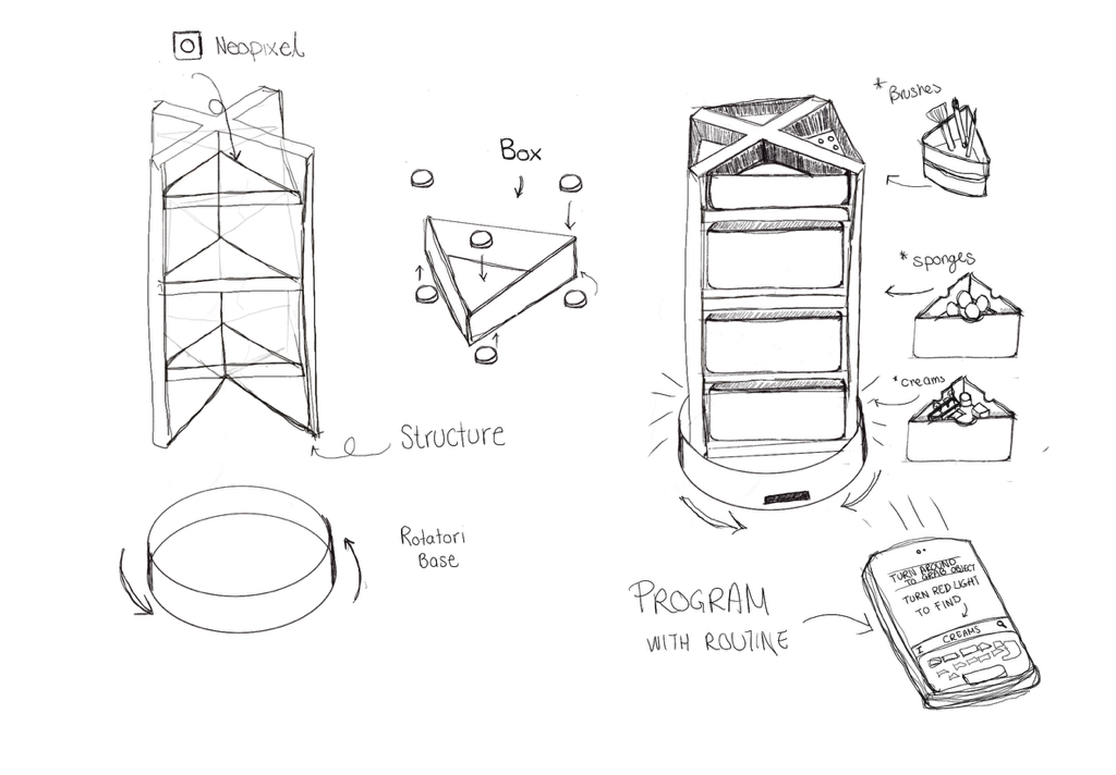
Description
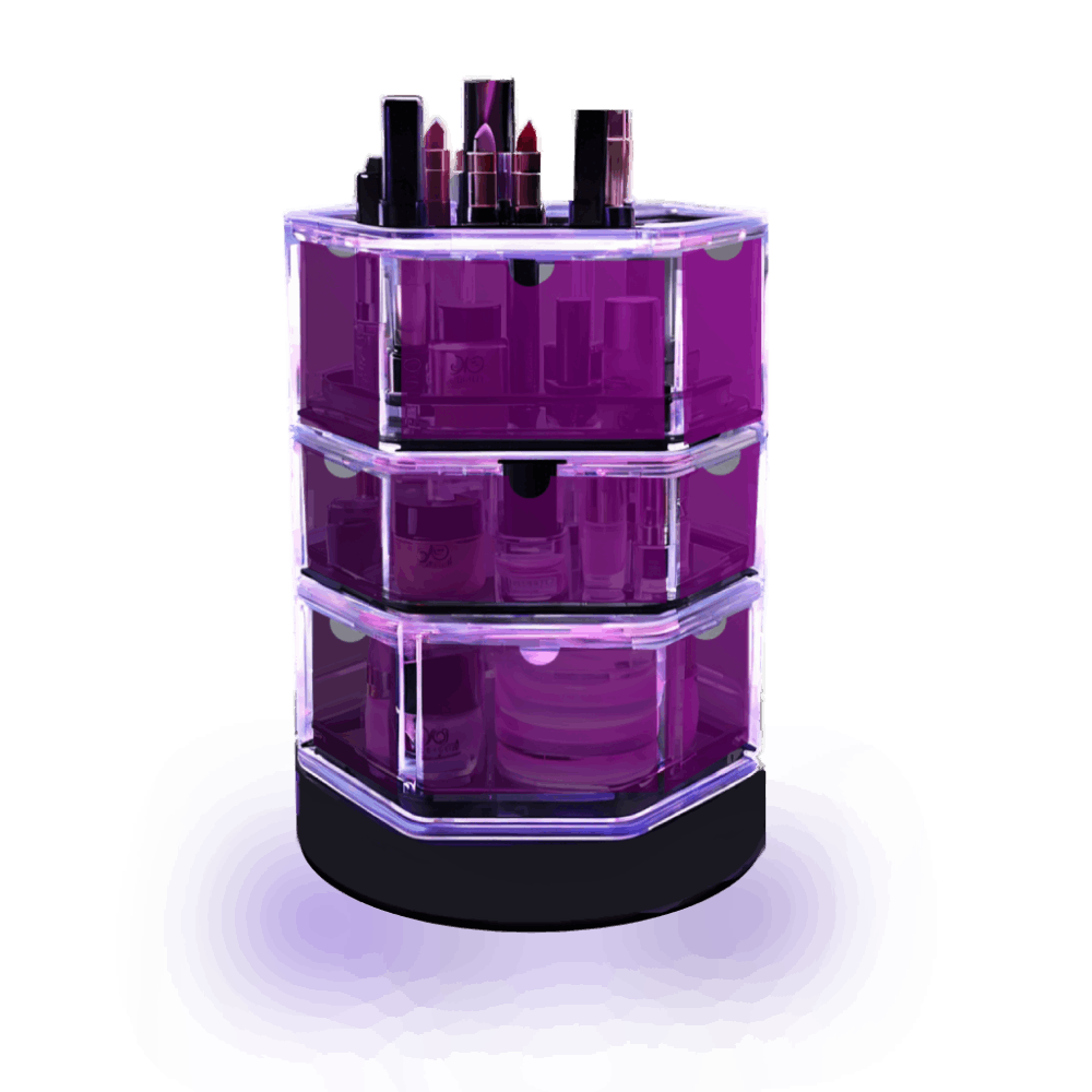
The Automated Rotatory Organizer is an innovative device designed to revolutionize how objects are stored, accessed, and organized. It employs advanced automation technology to enhance convenience and efficiency in home and office environments.
Key Features:
- Rotatory Functionality: Automatically rotates to allow easy access to stored items.
- Object Selection: Users can select items using an interface which they can personalize
- Modular Design: Allows for customization and easy replacement of components.
- User-friendly: Designed with intuitive controls and ergonomic considerations.
Applications:
The Automated Rotatory Organizer is suitable for various applications:
- Home Organization: Efficiently stores and retrieves small and medium items, tools, and personal belongings.
- Office Use: Organizes office supplies, files, and documents for quick access.
- Retail Displays: Showcases products in a retail environment, providing easy customer access.
- Industrial Storage: Manages parts and components in manufacturing and assembly settings.
Technological Advancements:
Powered by state-of-the-art technology, the Automated Rotatory Organizer includes:
- Advanced Detection: Detects user interaction and object positions accurately.
- Control System: Ensures precise and smooth operation to grab objects.
- Connectivity Options: Integrates with USB cable to any computer device
- Energy Efficiency: Designed with a power generator that gets the exact energy necesary t work.
Future Development:
In the future, the Automated Rotatory Organizer will be enhanced with:
- Mobile App Interface: Allows users to manage and control the organizer from their smartphones.
- Expanded Storage Options: Offers larger capacities and customizable compartments.
- Enhanced Security: Includes features such as biometric access or secure locking mechanisms.
- Environmental Sustainability: Incorporates eco-friendly materials and energy-efficient technologies.
PREVIOS INVESTIGATION
Whast I find intresting about this proyect is the diferent ways to track move and translate that info to a screen heres id some examples of posible convinations to start this proyect


- LED Mouse Blueprint
- Snowl Wireless Finger Mouse with 9DoF Technology
- Sensorized Glove
- Hand gesture recognition with Leap Motion
ToolFInder by Ximena Mendieta is licensed under CC BY-NC-SA 4.0
Schedule
Gantt Chart
| Activity | Status | Start Date | Due Date | Duration |
|---|---|---|---|---|
| Research | Done | 01/01/2024 | 28/01/2024 | 6 days |
| Previous Works | Done | 01/01/2024 | 28/01/2024 | 6 days |
| Sketch | Done | 01/01/2024 | 28/01/2024 | 3 days |
| Define materials | Done | 29/01/2024 | 17/02/2024 | 5 days |
| Proto | Done | 18/02/2024 | 01/03/2024 | 5 days |
| Make PCB | Done | 02/03/2024 | 15/04/2024 | 4 days |
| Design Interface | Done | 16/04/2024 | 20/04/2024 | 7 days |
| Program | Done | 21/04/2024 | 30/04/2024 | 10 days |
| Print and Cut pieces | Done | 21/04/2024 | 30/04/2024 | 8 days |
| Slide | Done | 02/03/2024 | 15/04/2024 | 2 days |
| Test | Done | 01/05/2024 | 05/05/2024 | 2 days |
| Assemble | Done | 01/05/2024 | 13/05/2024 | 4 days |
| Final Touches | Done | 01/05/2024 | 13/05/2024 | 5 days |
| Video | Done | 14/05/2024 | 19/05/2024 | 2 days |
| Presentation | Done | 20/05/2024 | 10/06/2024 | 1 day |
Weeks Used in the Final Project
3. Computer Controlled Cutting …
13. Networking and Communication …
14. Interface and application programming …
17. Applications and Implications …
18. Invention, Intellectual Property and Income …
Materials and Components approximate price
- Xiao ESP32C3 - $200.00 MXN
- NEMA 17 Motor - $300.00 MXN
- Neopixels - $250.00 MXN
- Acrylic Sheets - $150.00 MXN
- PLA Filament - $500.00 MXN
- 12V Power Supply - $400.00 MXN
- Resistors - $25.00 MXN
- Pin Headers - $30.00 MXN
- Connectors and Cables - $65.00 MXN
- Miscellaneous Hardware - $45.00 MXN
- Total - $1965.00 MXN
Parts and Systems
- PCB Design and Fabrication: Design and fabricate the PCB to house the Xiao ESP32C3 and other electronic components.
- 3D Printed Components: Print the base, shelves, and mounts for the motor and PCB using PLA filament.
- Assembly: Assemble the acrylic walls, Neopixels, motor, and other components into the final organizer.
- Programming: Develop the software to control the motor and lights, and to handle user inputs for selecting and retrieving items.
Processes
- PCB Fabrication
- 3D Printing
- Laser Cutting
- Vinil Cutting
- Programming (Microcontroller and Neopixels)
- System Integration
- Testing and Calibration
System Integration Diagram
-
PCB Design and Fabrication
- Xiao ESP32C3
- Pin Headers
- Resistors
- Connectors and Cables
-
3D Printed Components
- PLA Filament
-
Assembly
- Acrylic Sheets
- NEMA 17 Motor
- Connectors and Cables
- Neopixels
- Miscellaneous Hardware
-
Programming
- Xiao ESP32C3
- Motor
- Neopixels
-
Processes
- PCB Fabrication
- 3D Printing
- Laser Cutting
- Vinil Cutting
- Programming
- System Integration
- Testing and Calibration
Automated Rotary Organizer Project
This document outlines the steps I took to create my final project, an automated rotary organizer. Below is a detailed description of each phase of the project.
1. Project Management
In the initial phase, I planned and managed the entire project. This included setting milestones, creating a timeline, and ensuring all necessary resources and tools were available.
2. Computer Aided Design (CAD)
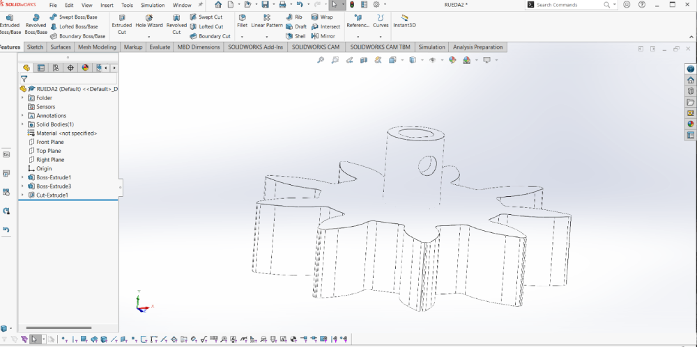
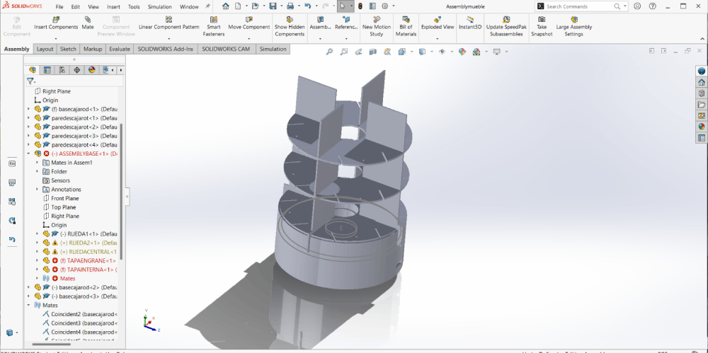
I used SolidWorks for 2D design to create all the printed pieces. This allowed me to visualize the components and ensure they would fit together correctly before printing.
3. Computer Controlled Cutting
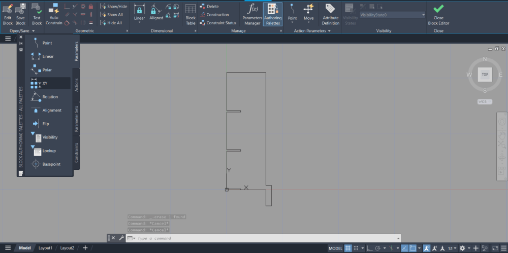
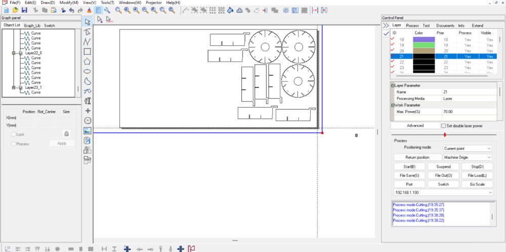
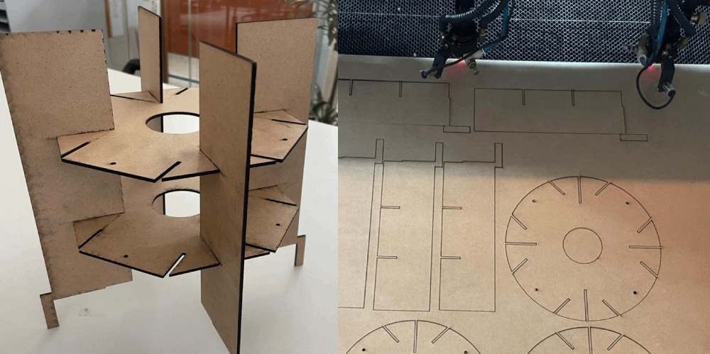
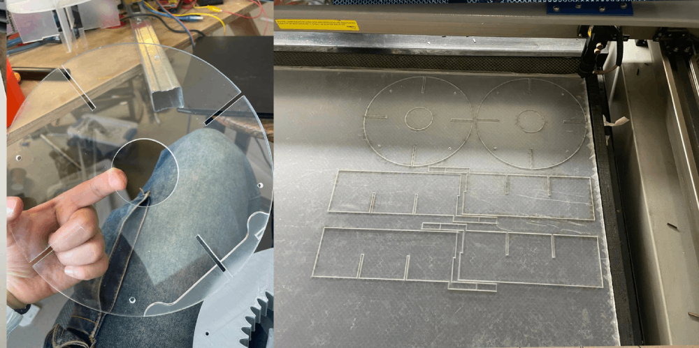
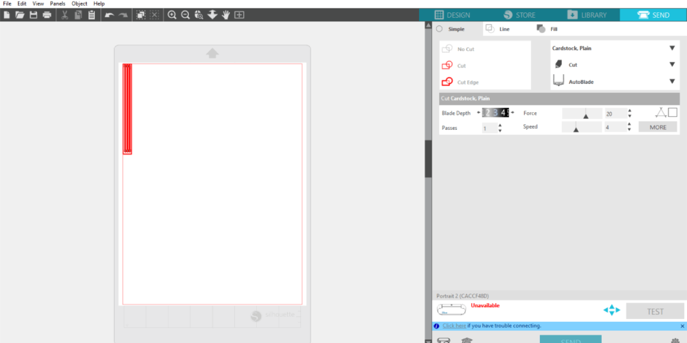
Next, I performed laser cutting. I started with several test cuts to ensure precision and accuracy. This step was crucial for creating the base and structural components of the organizer.
4. 3D Printing
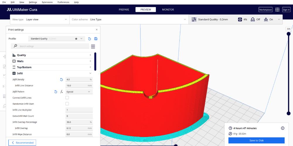
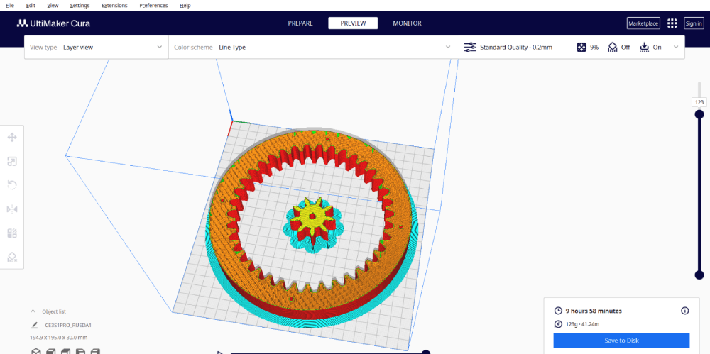
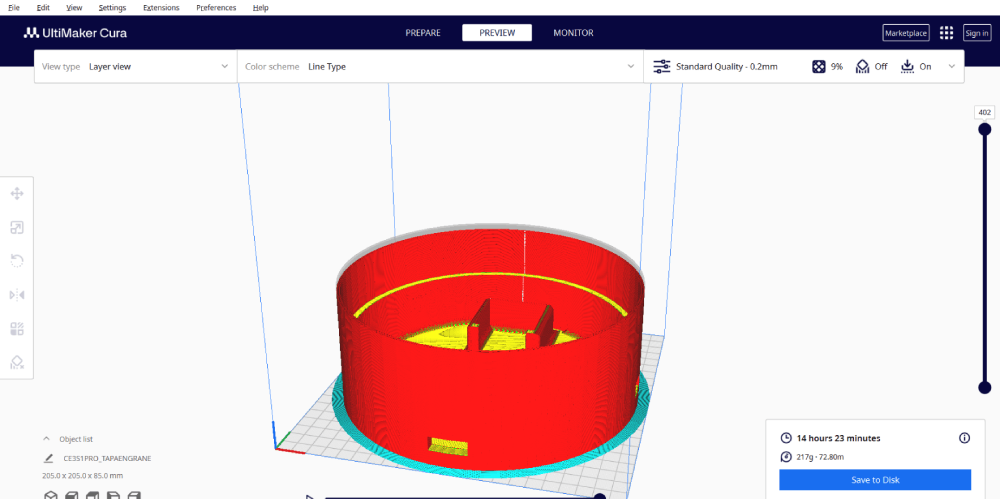
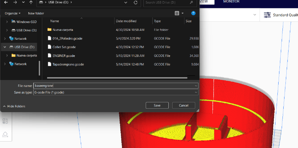
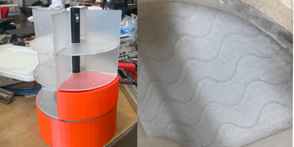
I used 3D printers to print various parts of the organizer, such as the base, the rotary mechanism, and the boxes. These printed pieces were essential for the assembly of the organizer.
5.Electronics Design
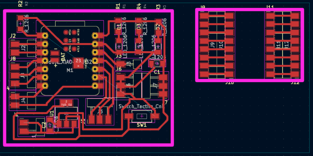
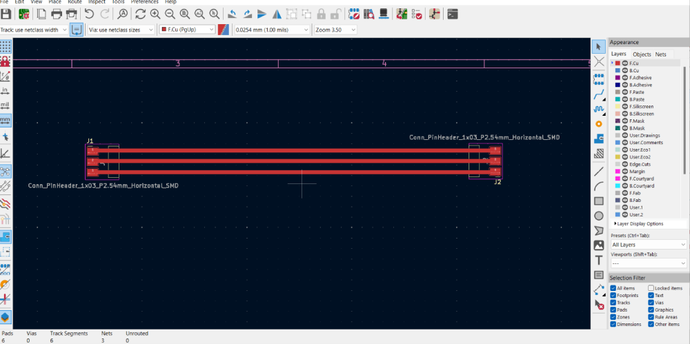
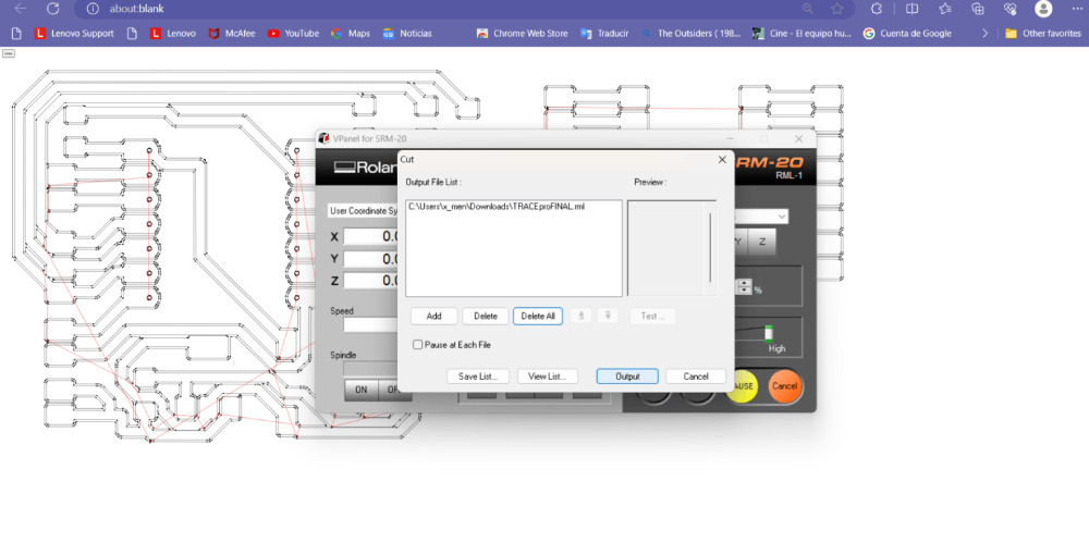
I designed the PCB for the project, using the Roland SMR 20 for CNC cutting. After manufacturing the PCB, I tested its functionality to ensure all components worked together seamlessly.
6. Electronics Production
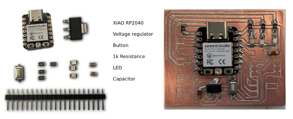
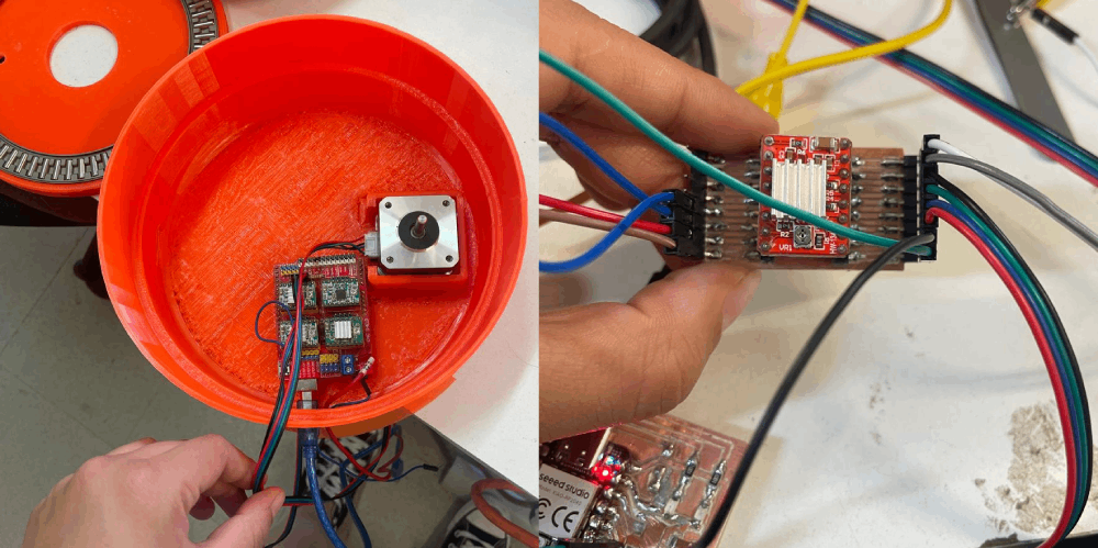
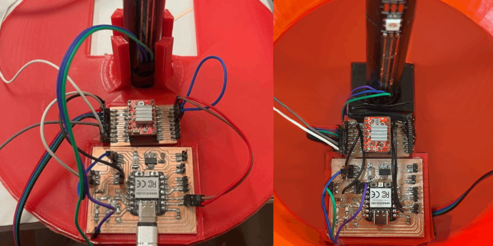
I began the electronics production by designing the circuit and selecting components. This involved welding all necessary parts and connecting a Nema 17 stepper motor with a driver A4988 and a string of 12 Neopixels.
7. Embedded Programming
I programmed the Nema 17 motor and the Neopixels sequence to ensure the organizer rotates and lights up as intended. This step involved writing and debugging code to control the electronics.
8. Networking and Communication
In this phase, I explored ways to enable communication between different parts of the system. This included setting up protocols like I2C for data exchange and ensuring reliable connectivity.
9. Interface and Application Programming
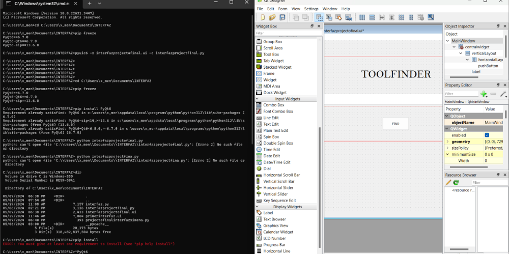
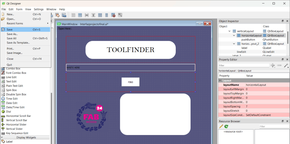
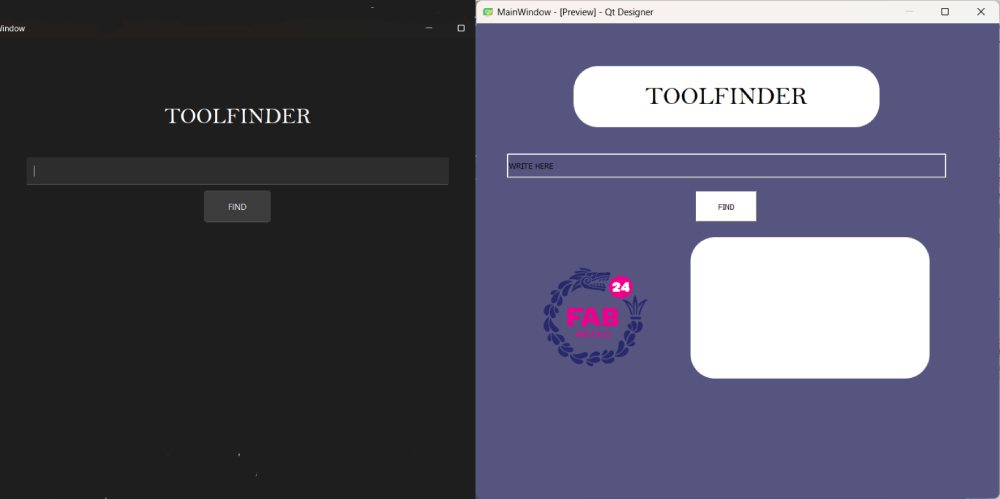
I developed an interface to control the organizer, allowing users to interact with the system easily. This involved programming user-friendly controls and integrating them with the organizer’s electronics.
10. Wildcard Week
During Wildcard Week, I explored additional features and improvements for the organizer. This included experimenting with different materials and design modifications to enhance functionality.
11. System Integration
I integrated all the components and subsystems into a cohesive unit. This step ensured that the mechanical, electronic, and software parts of the organizer worked together as intended.
12. Applications and Implications
I evaluated the practical applications and implications of the automated rotary organizer. This involved assessing its usability, potential market, and the impact it could have in relevant fields.
13. Invention, Intellectual Property, and Income
Finally, I considered the invention's intellectual property aspects and potential income. This included researching patents, licenses, and strategies for monetizing the product.

ToolFInder by Ximena Mendieta is licensed under CC BY-NC-SA 4.0
Files
Assembly and Solutions
This document outlines the steps I took to create my final project, an automated rotary organizer. Below is a detailed description of each phase of the project, including assembly, mistakes encountered, and solutions implemented.
1. Assembly
The assembly phase involved putting together all the 3D printed parts, laser-cut components, and electronics. This step was crucial for ensuring that all parts fit together correctly and functioned as intended.
During assembly, I encountered several challenges such as aligning the motor with the second layer to prevent vibrations. I also had to ensure that all cables were securely connected to avoid disconnections due to pressure.
2. Mistakes Encountered
Several mistakes were encountered during the design and assembly process:
- Kerf of the Acrylic: The laser cutting process introduced a kerf in the acrylic, which affected the dimensions and fit of the parts. I had to adjust the design to account for this kerf.
- PCB and Motor Spacing: There was an issue with the space between the PCB and the motor. Initially, the spacing was too tight, causing connectivity problems. I had to redesign the layout to provide adequate space.
- Cable Disconnections: The cables got disconnected due to the pressure from the motor. I addressed this by using stronger connectors and securing the cables more effectively.
- Motor Vibrations: The motor caused vibrations which affected the stability of the organizer. To mitigate this, I scrolled and mounted the motor to the second layer, providing better stability.
3. PCB Cutting with CNC Router
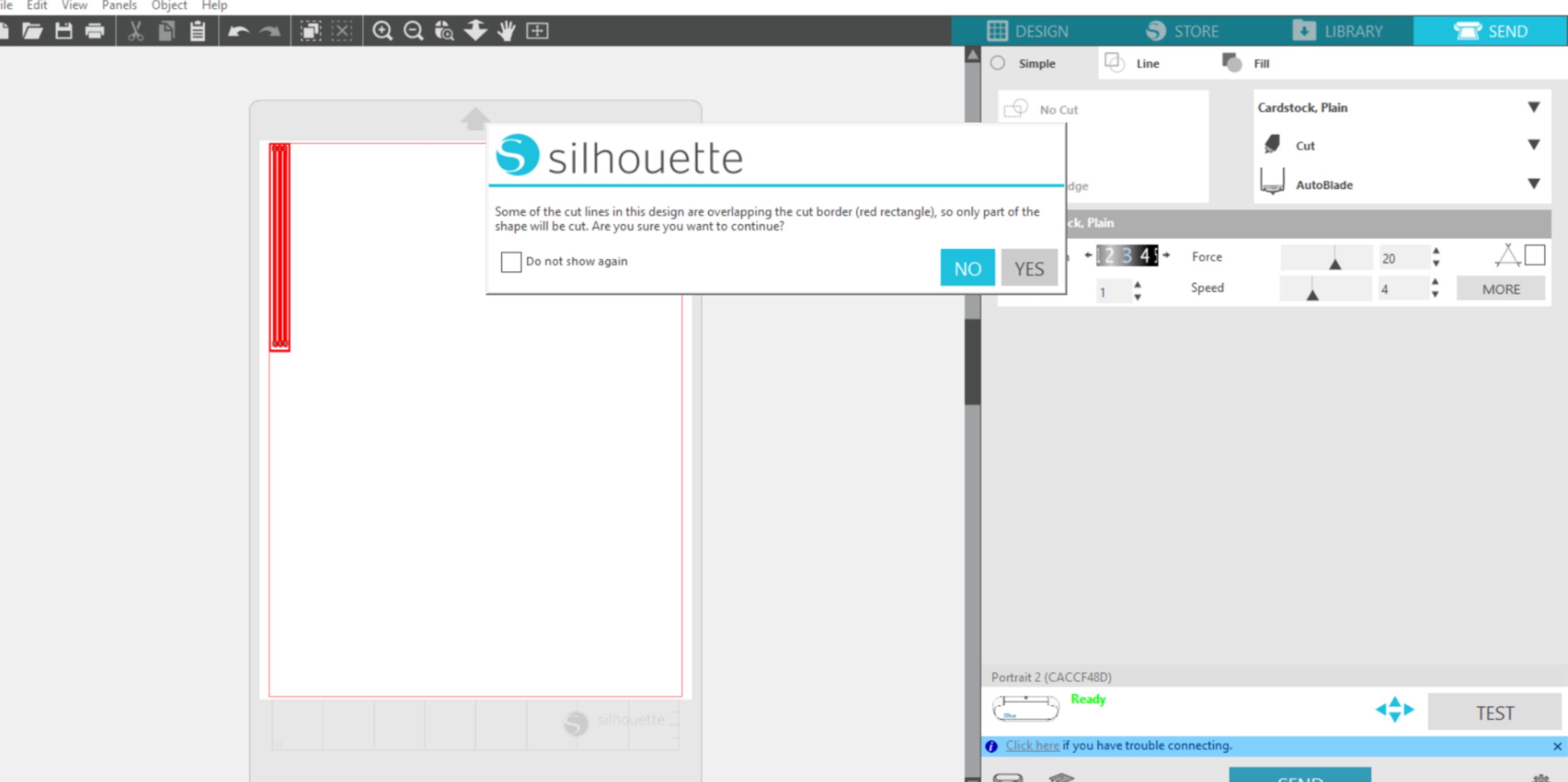
The PCB cutting was done using a CNC router, specifically the Roland SMR 20. This step involved designing the PCB layout, setting up the CNC router, and cutting the board to the precise dimensions required.
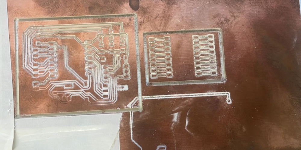
After cutting the PCB, I tested the connections and functionality to ensure that all components were properly connected and the circuit was working as intended.
4. Kerf of the Acrylic
The laser cutting process introduced a kerf in the acrylic material, which affected the precision of the cuts. I performed several test cuts to measure the kerf and adjusted the design files to compensate for it.
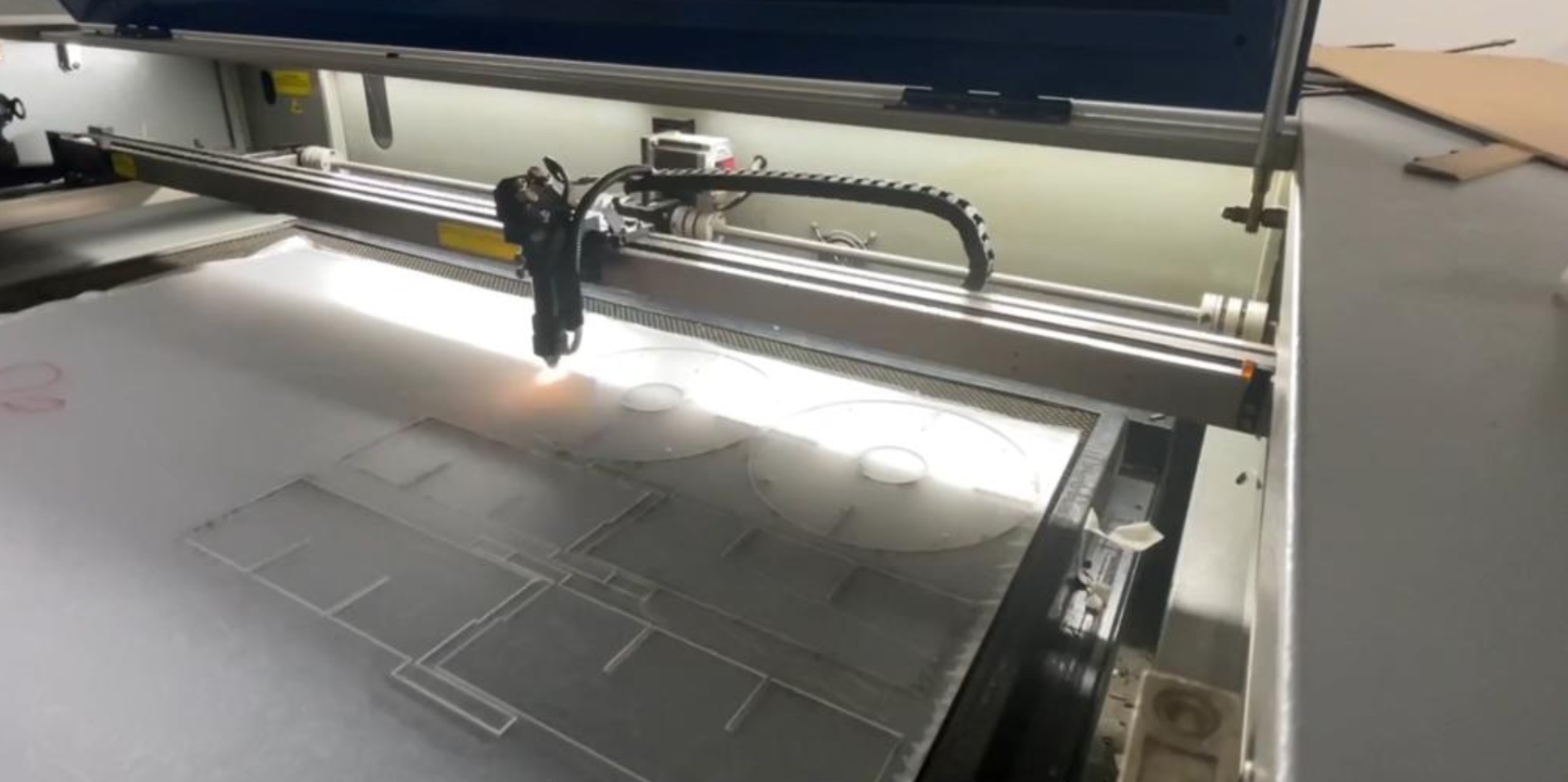
This adjustment ensured that the laser-cut parts fit together accurately without any gaps or misalignments.
5. Spacing Between PCB and Motor
The initial design had inadequate space between the PCB and the motor, leading to connectivity issues. I redesigned the layout to increase the spacing, ensuring that there was enough room for the components and connectors.

This redesign resolved the connectivity problems and allowed for easier assembly and maintenance.
6. Assembly Issues and Solutions
During the assembly, I encountered issues with cable disconnections due to pressure. To solve this, I used stronger connectors and secured the cables more effectively. Additionally, I addressed motor vibrations by mounting the motor to the second layer, providing better stability.
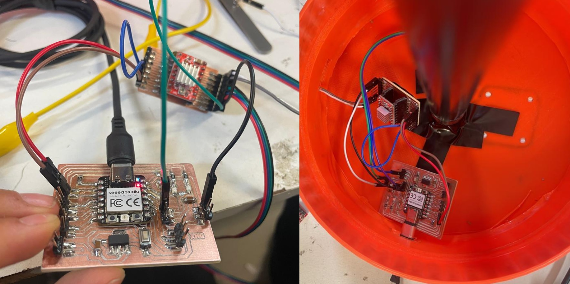
These solutions ensured that the organizer operated smoothly without any interruptions or mechanical issues.
ToolFInder by Ximena Mendieta is licensed under CC BY-NC-SA 4.0
My Final Project
Slide / Video
If you want to see the future plans for the project you can Click Here.
In case of the final cost, what will be done, designed parts and processed used, Click Here.
All the components, comunication and system integration can be found if you Click Here.
ToolFInder by Ximena Mendieta is licensed under CC BY-NC-SA 4.0
