Week 2: Computer Aided Design
To start this week I tried designing with diferent platforms to prove how they could be use. Analizing their pros and the limitations
List of Softwares
2D design
First we need to go to figma as an online designing platform we can create digital designs and save them in the same page with your profile. you can create the profile with an email adress

This will be some of the tools that we are going to use to design our engine system
- Trace Figures
- Measure objects
- Trace and curve lines
- Join lines
- Edit Layers
- Copy/ Paste
- Erase lines
- Fill objects
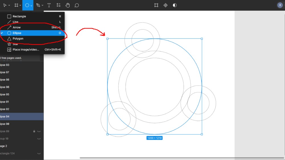
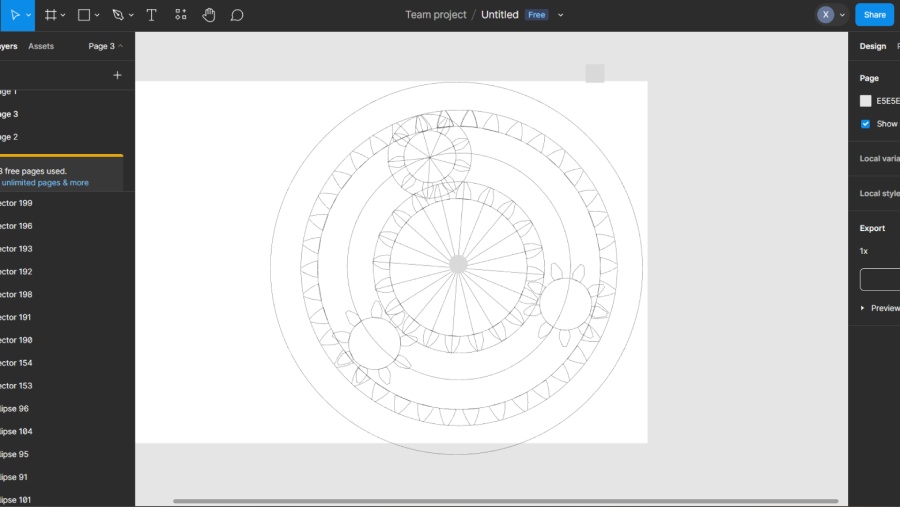
First, let's talk about shapes. At the top of the page, there's a toolbar.To draw a shape, you need to click on the circle icon and drag the control from the top to the bottom in the drawing space
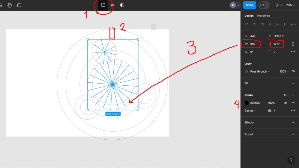
To modify this shape, you can select the image or click on the top toolbar. The rectangle icon represents shapes and their vectors. In the panel on the right, you can adjust the height and width, as well as the coordinates of the image's placement.
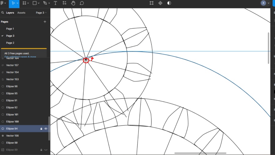
To edit a vector, click on the line. At the top, you can change whether you want the line to be sharp or curved.
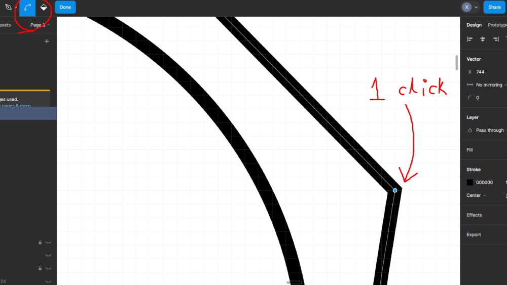
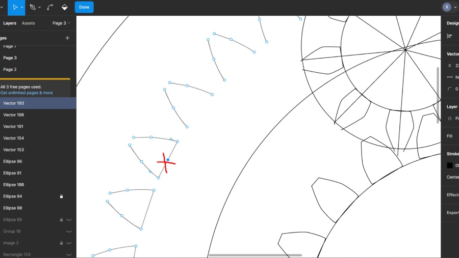
In the toolbar, there's a pen or pencil icon that allows you to trace lines. If one of the lines, as shown in the image below, is not touching the other, it will not create a shape. To solve this, you can drag the line to close the gap.
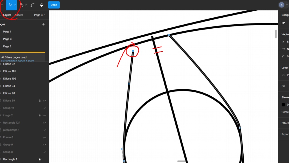
Once you do so, you can check the shapes, groups, and all your pages in the display at the side of the drawing space.
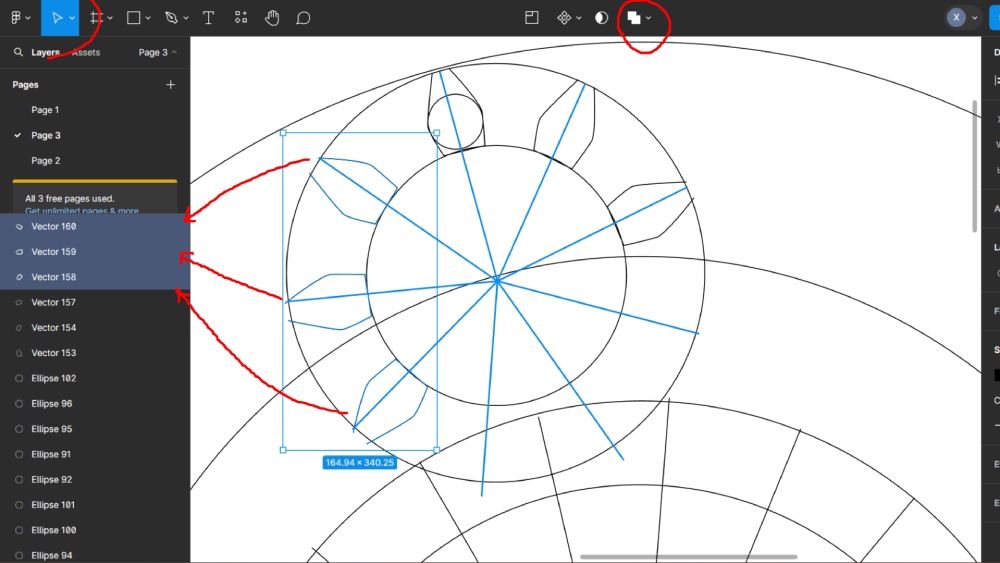
You can also toggle the visibility of the layer or hide it as needed.
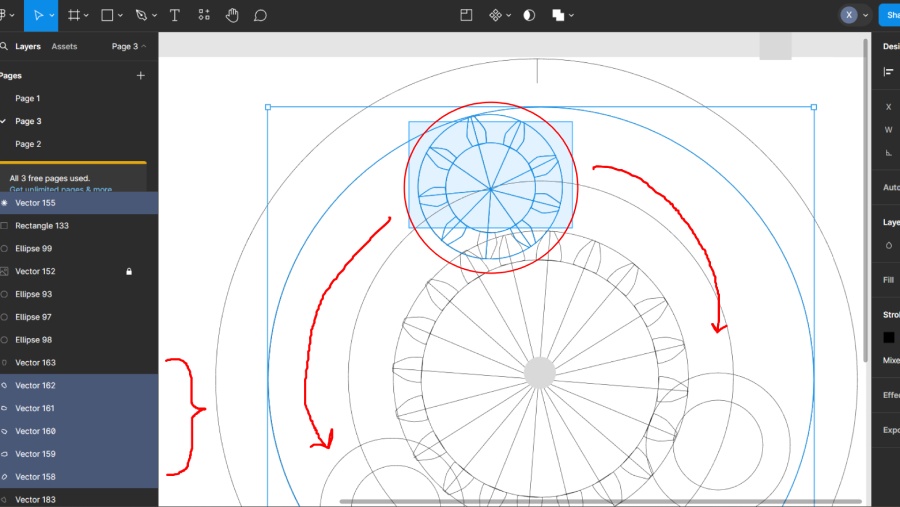
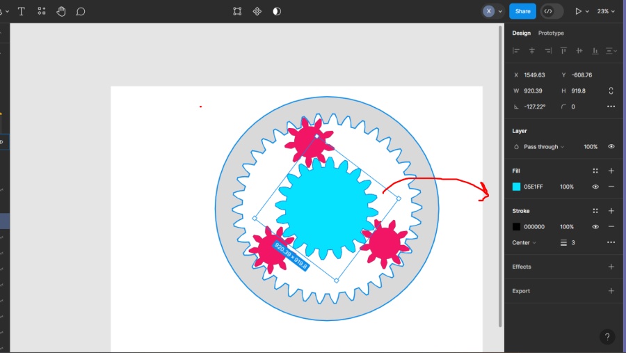
Then you can select objects draging the cursor and copy and paste the objects that you need, some tips may be group your selection and draw exacly a line were you want the object to be then paste it rigth in the middle.
If you want to delete an object but use some of the lines you can ider delete it and close vectors or select the shape,
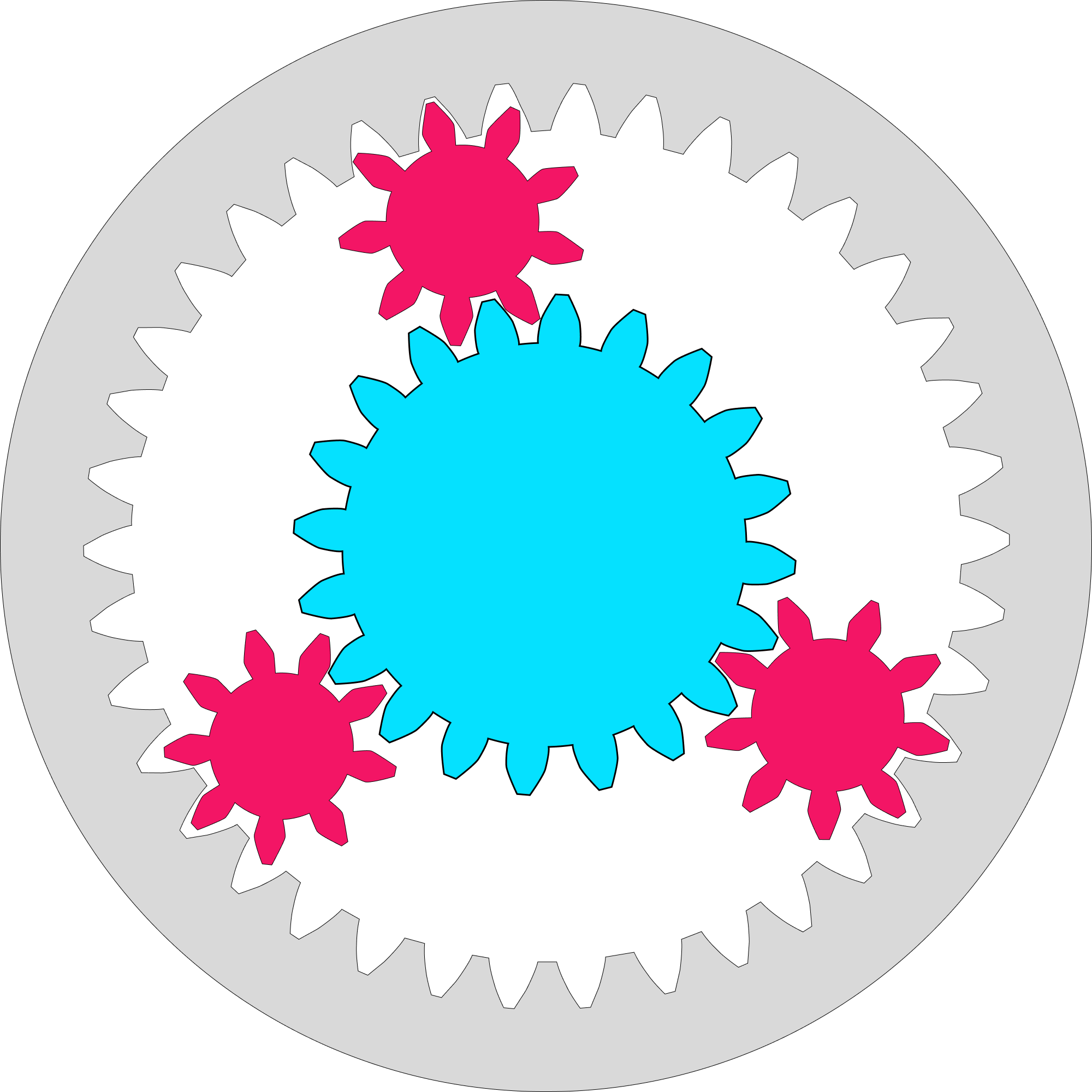
This is how the image should like like in orther to create the engine
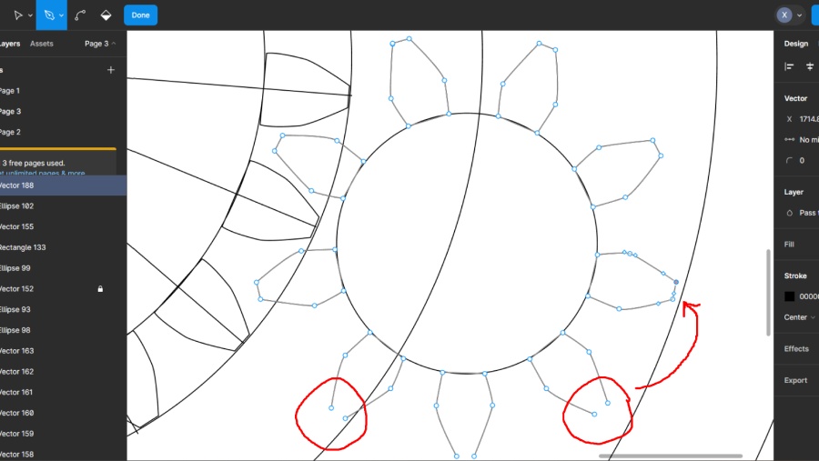
Doble click and grite vectors and delete just delete the conections and leave the ones you made
Also, if you already have a shape and you want to unite them, you can select both shapes and click the two squares icon.
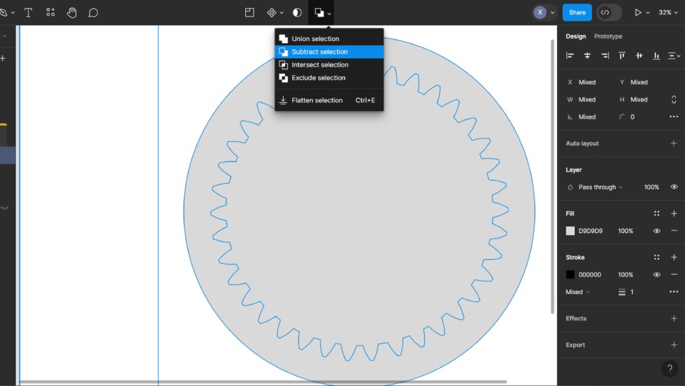
Depending on which shape you want to cut, you select the union option.
Final
- AUTOCAD
- Trace Figures
- Measure objects
- Trace and curve lines
- Join lines
- Edit Layers
- Copy/ Paste
- Erase lines
- Create canva
- Insert image
- Trace figures
- Distor objects
- Arange objects
- Add Color
- Cut objects
- Download images
First I install the software or use the online version at AUTOCAD WEB that allows you to save the documents with your profile or in drive

I personally desided to use AUTOCAD software and some of the tools that we are going to use to create the same engine will be:
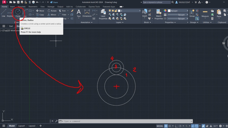
With AutoCAD, you have more advanced features and the ability to measure distances between traces. To create the exact same piece, I used the shapes at the beginning of the toolbar in the Home tab. I placed the first shape and then created smaller ones with a 1 cm offset.
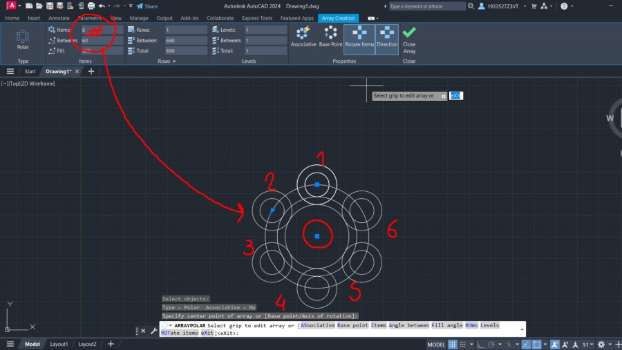
Then, I used the Array tool to create a pattern for drawing the smaller shapes. When you click Array, you have the option to select the distance between objects and the number of items.
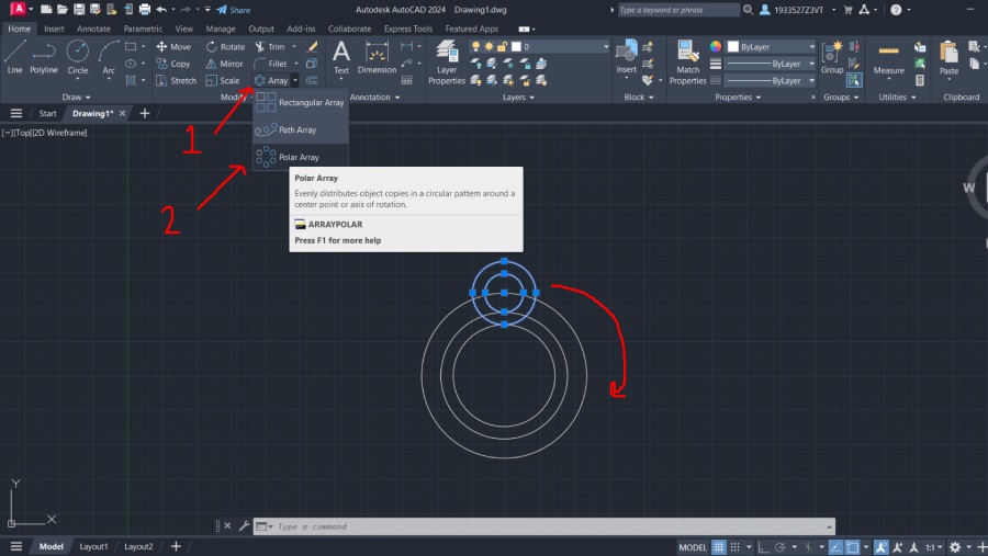
In this case, I used three shapes with the same space between each of them.
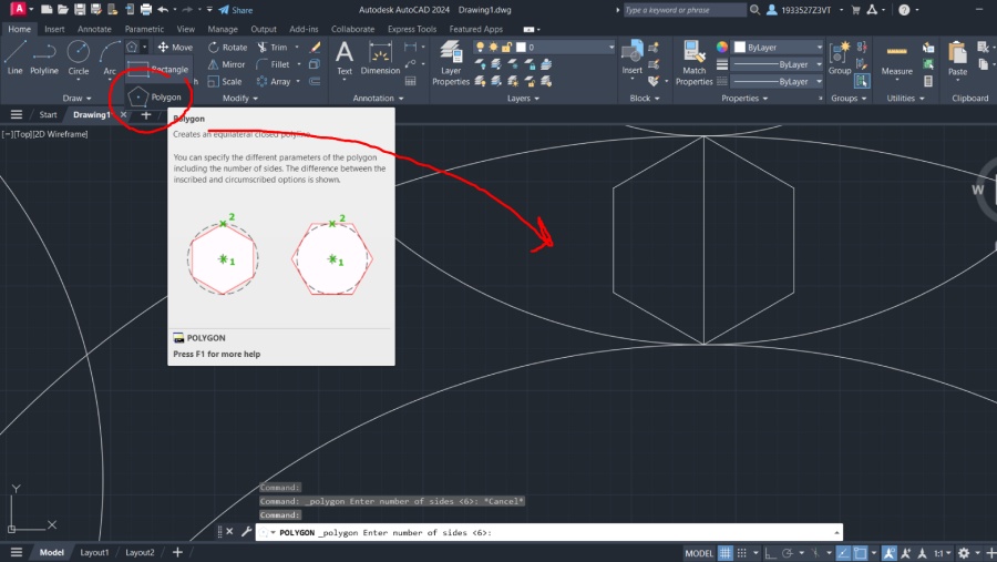
For the gear tooth, first I got the perimeter and calculated the number of teeth I needed. Then, I traced a polygon and trimmed the base to connect it with the center.
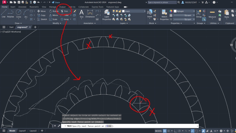
To compleate the figures I used trim and extend for them to close the teeth
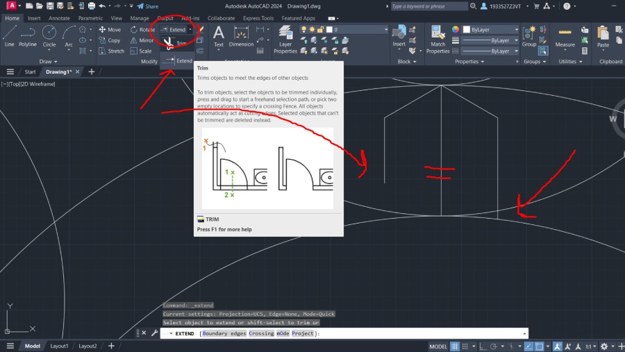
And finally I used the same Array tool to create the missing gears.
Then add measures in other layer with different colors so you dont forget the dimensions. First drawing basic rectangles and then added fillet and round corners to make it more dinamic.
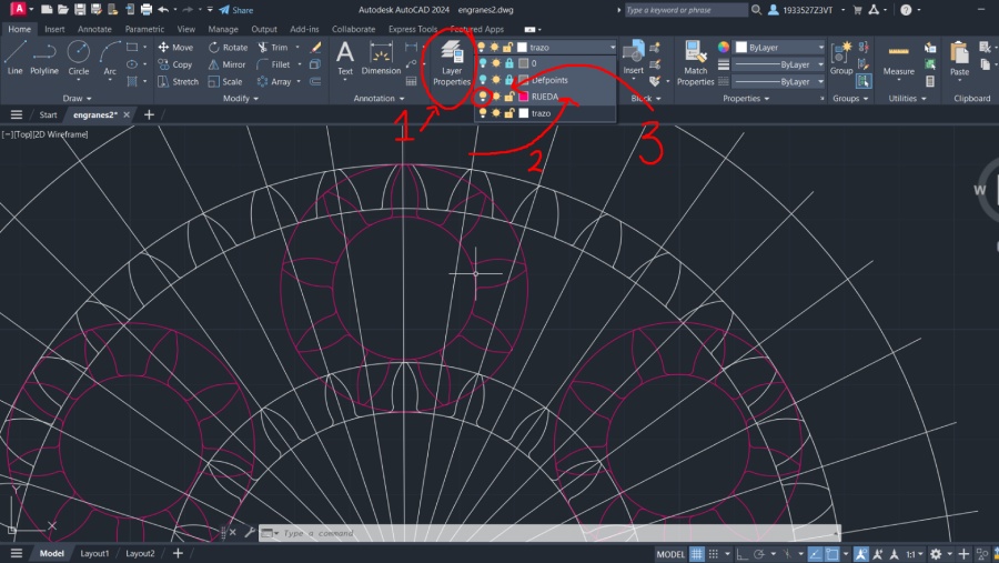
To erase the marks I made I used trim. The great thing about this tream is if you keep the finguer in the mouse once you click you can erase all the lines you need at the same time
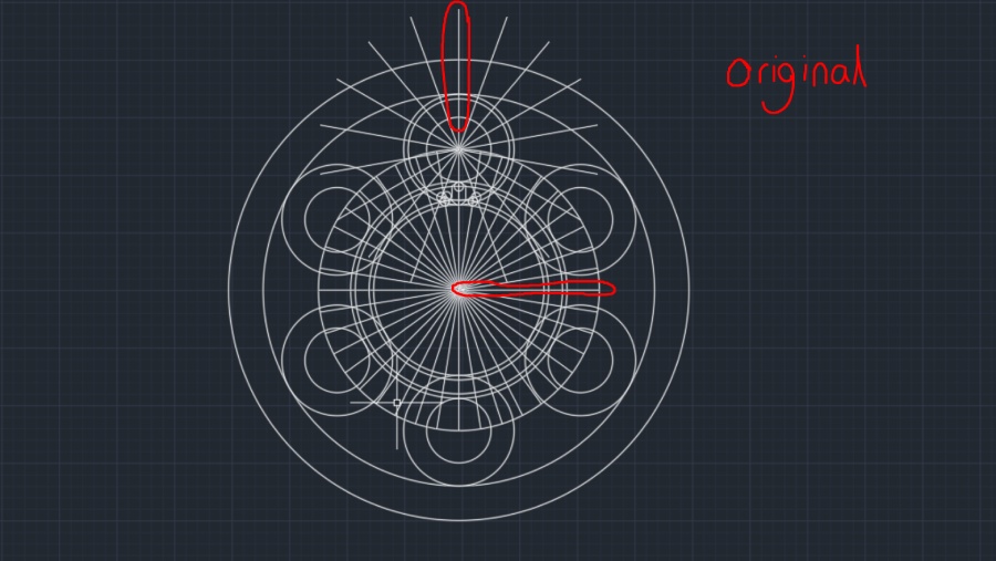
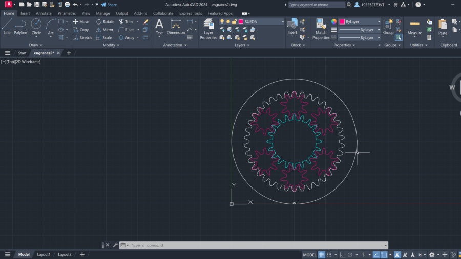
At last I turn all the layers To see the gears and this must be the finall result. You can export each layer or all togther or cut them and paste them all in the same layer but I recomend it this way for them to be able to be ajusted I you need them with out the risk of selecting other lines.
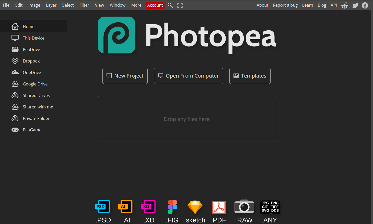
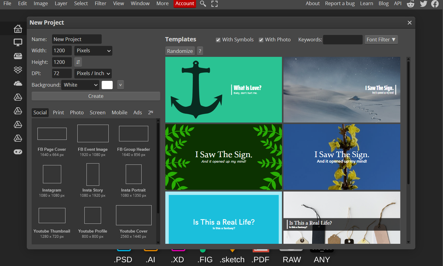
To use Photopea you need to enter any server and look for for the web site

In this page you need to clik in New Project to create a canvas
To insert an image in Photopea, you can click on the top menu and go to File > Open & Place, then select the document. Alternatively, you can drag the image you want from a folder to the canvas.
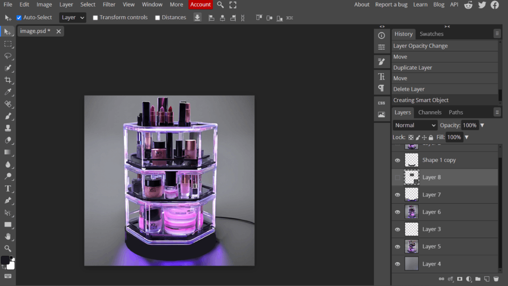
To change the color of the boxes in your images, select the rectangle tool and draw a simple rectangle. You can choose any color for the fill and stroke at the top of the canvas.
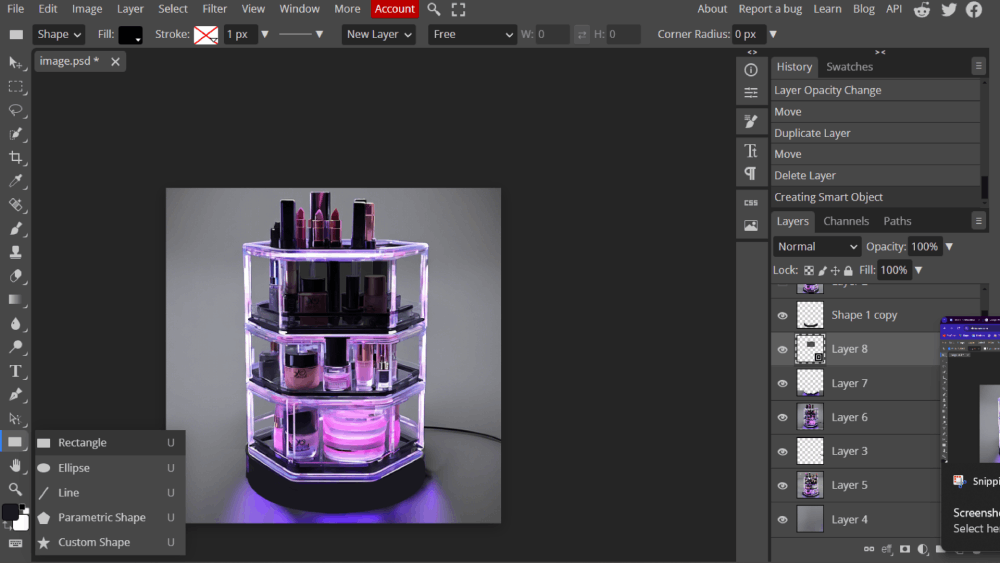
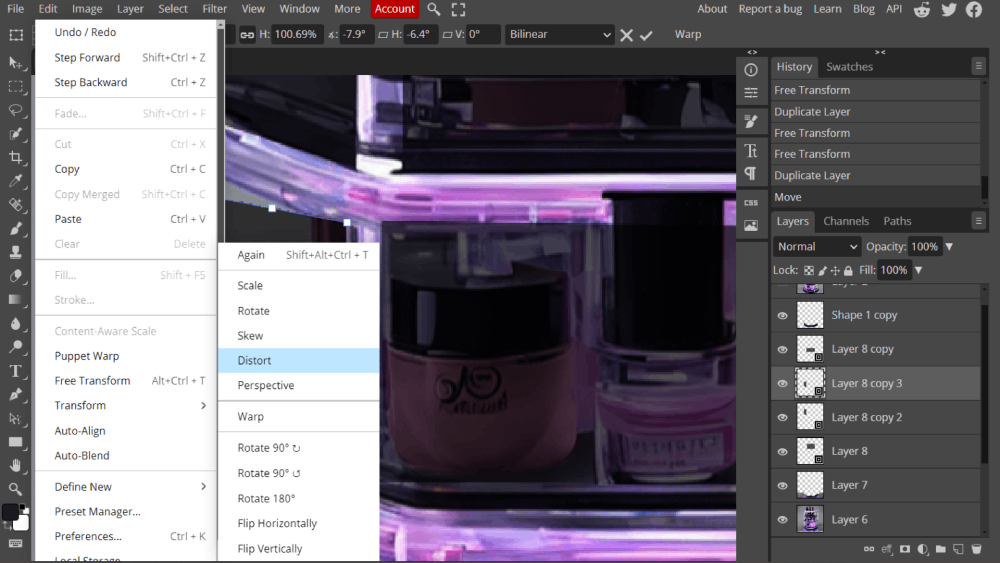
Once you are satisfied with the shape, you can distort it using the option at the top menu by going to Edit > Distort.

With the same tool, you can drag the vector to match the frame of the boxes.
If they all have the same shape, you can use Ctrl + C and Ctrl + V to copy and paste the shapes.
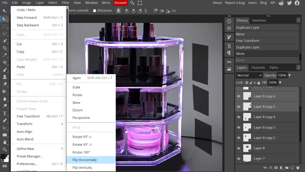
Select the shapes in the layers panel and do the same on the other side. To avoid repeating the distort process, you can select "Flip Horizontal" to mirror the objects.
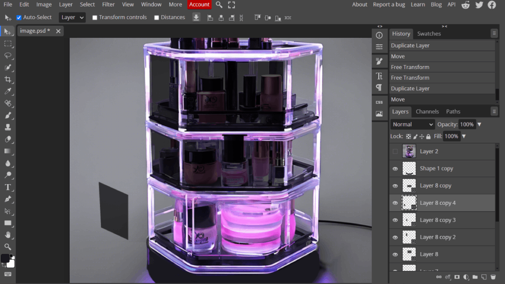
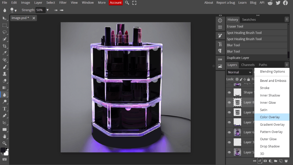
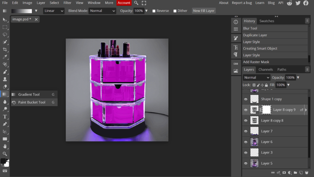
If we want to change the color of all the boxes at once, we can select the layers and use the "Color Overlay" option to paint them.
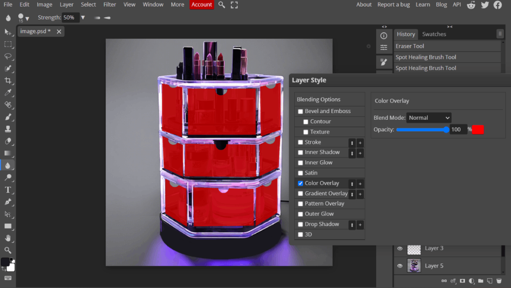
Once you click this option, you can select the color and the intensity you want them to have. To simulate the transparency of the object, we are going to use a gradient to show where the light hits the object and the shadow it creates.
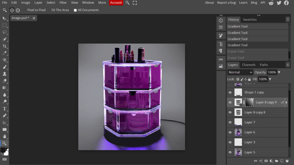
Open a small window using the tool next to "eff," and select the white rectangle. Then, with the gradient tool, drag the mouse from one side to the other, depending on which side you want the white or black color to appear.
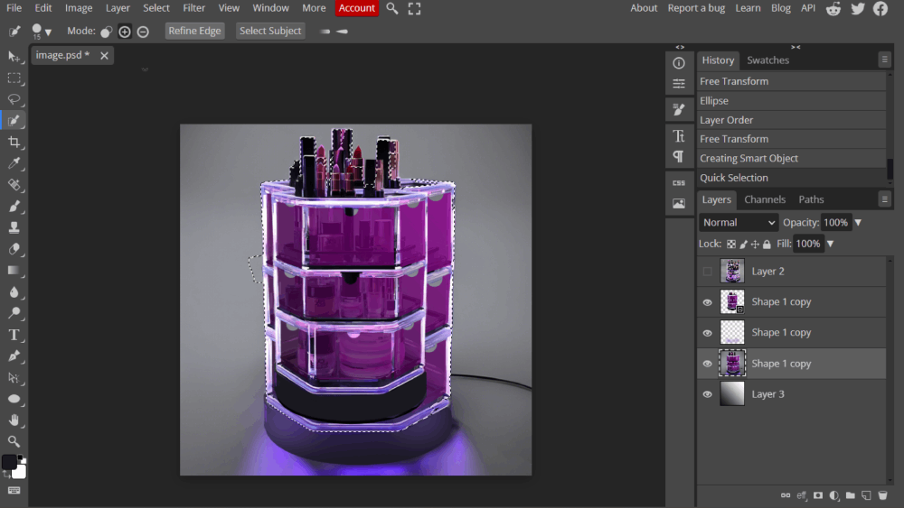
It will look something like this photo. To erase the background so that we only have the main object in the picture, we are going to use the object selector tool, which looks like a pencil with a circle behind it.
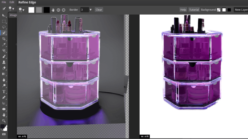
Then, click on "Refine Edge," and a window will pop up where you can refine the selection.
Use black to mark the areas you don't want to select, white for the object you want to keep, and gray for the border to soften the edges.
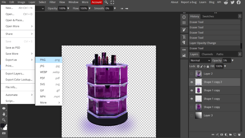
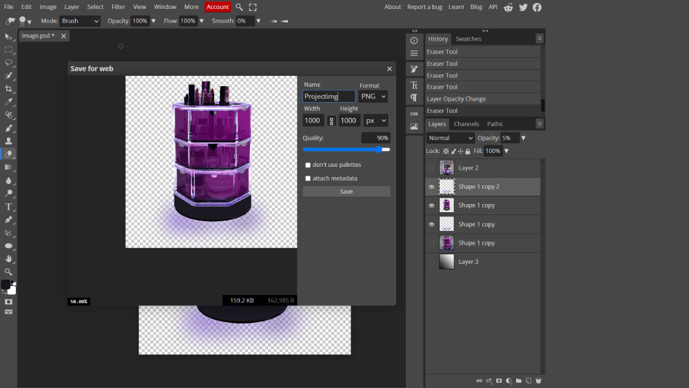
To save your work you need to clik File> Export as> PNG justo save the image without background, or JPG to save the hole image or save PSD to save all the editable layers
3D Modeling
With Fusion 360 I follow a simple tutorial to

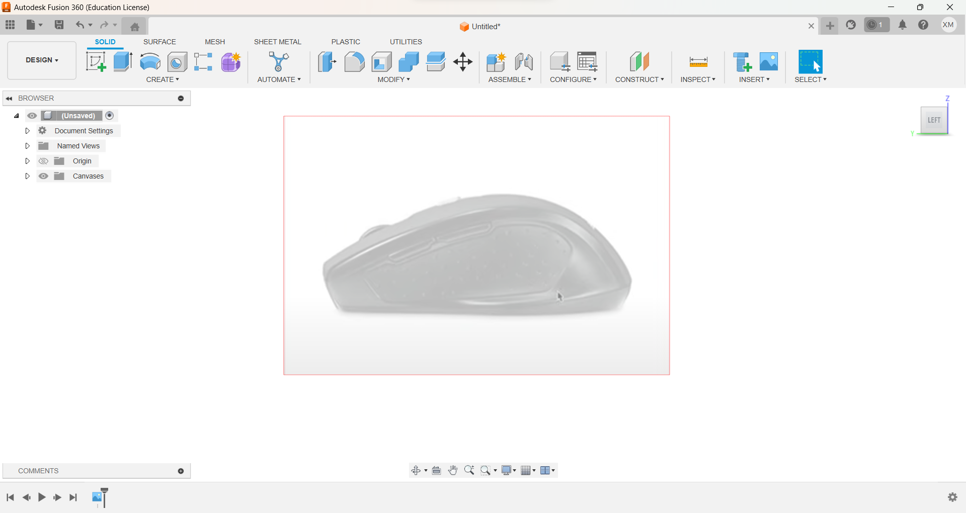
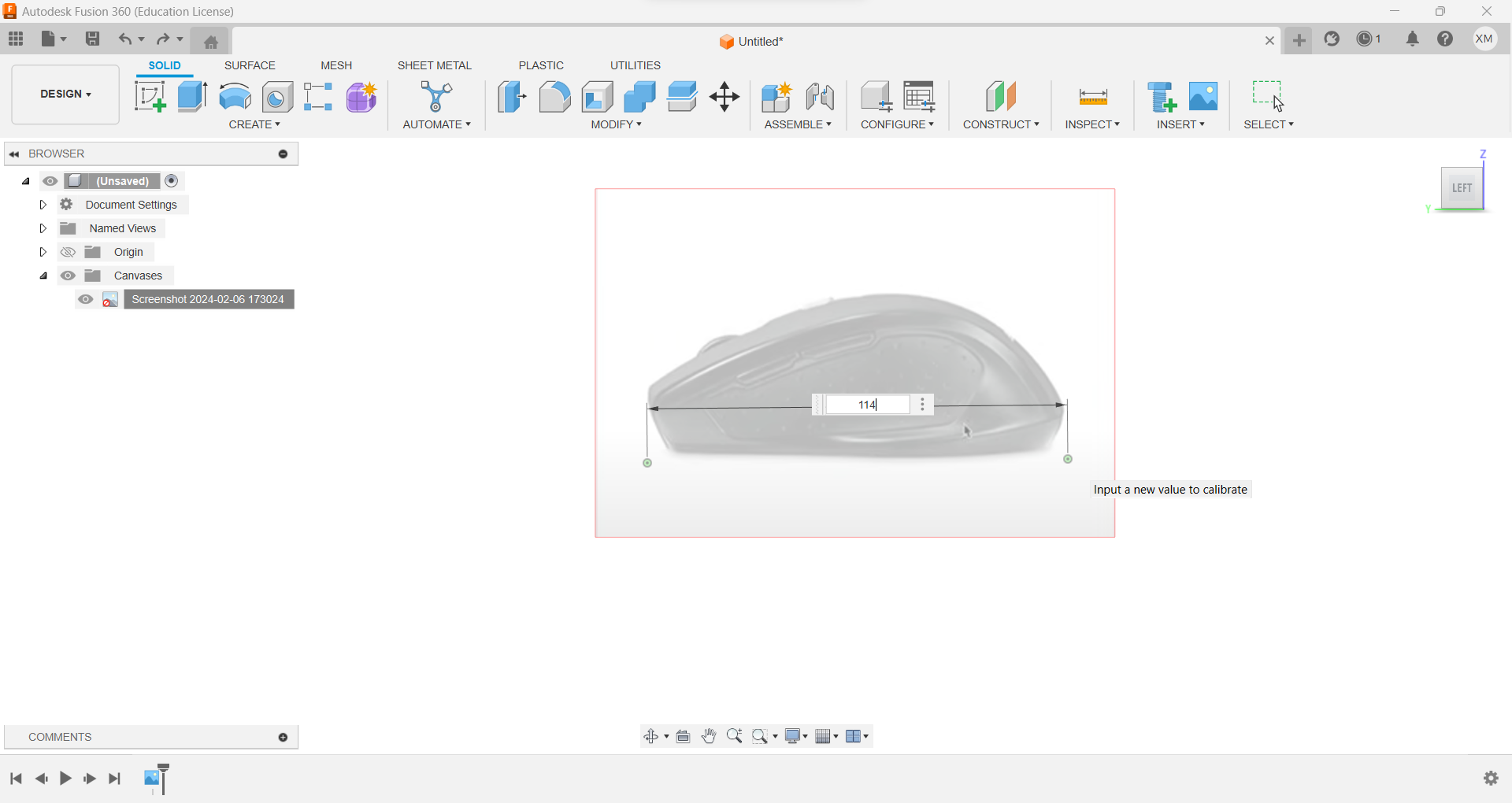
Insert reference image. To do so click insert in the toolbar and select the image
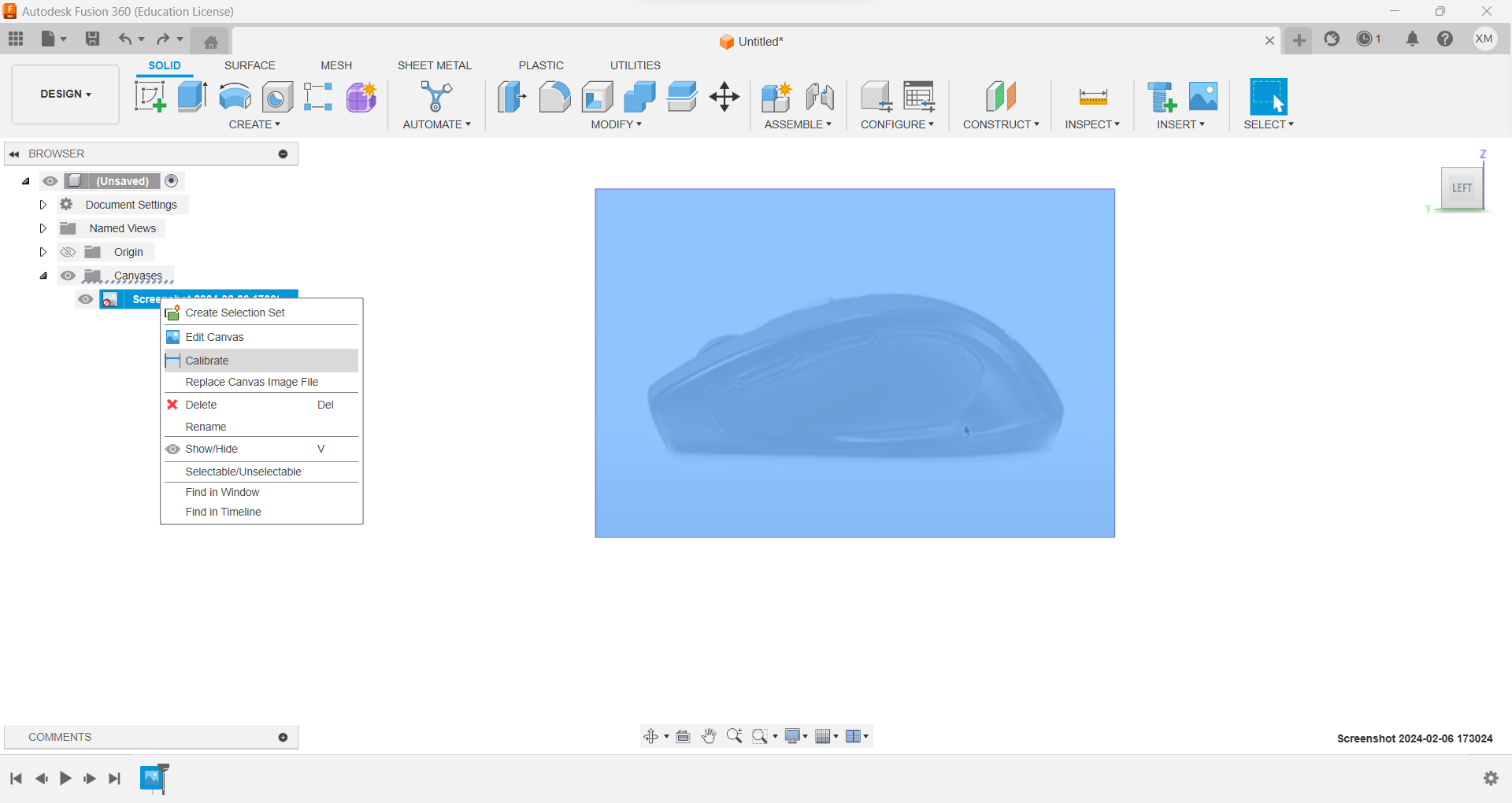
Calibrate the image using tools on the left With two reference points, place the approximate measurement of the object in the image.
Insert the proximate size of the object that you are modelating in order to have the same proportions, I recommend to use a bernier to get the measurements.
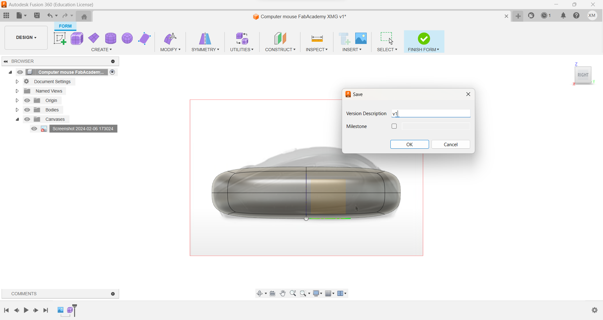
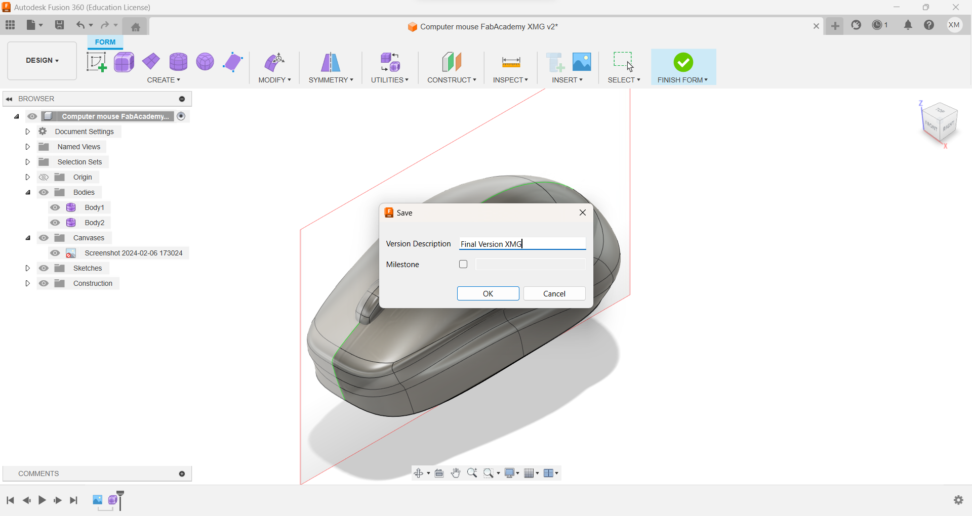
Then insert an object, in this case, the most similar was the cube, and save the versions.
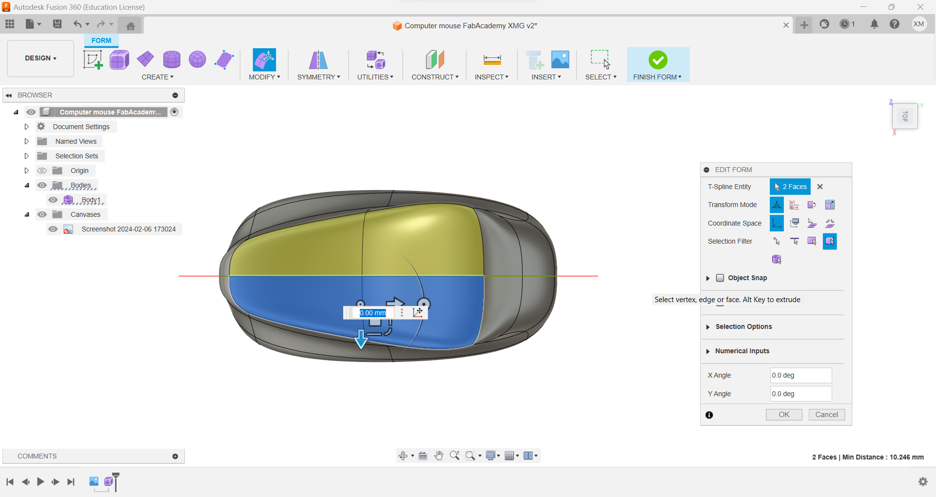
Click edit form to dislay the coursor with this options. Double click to select the "edit form" tool
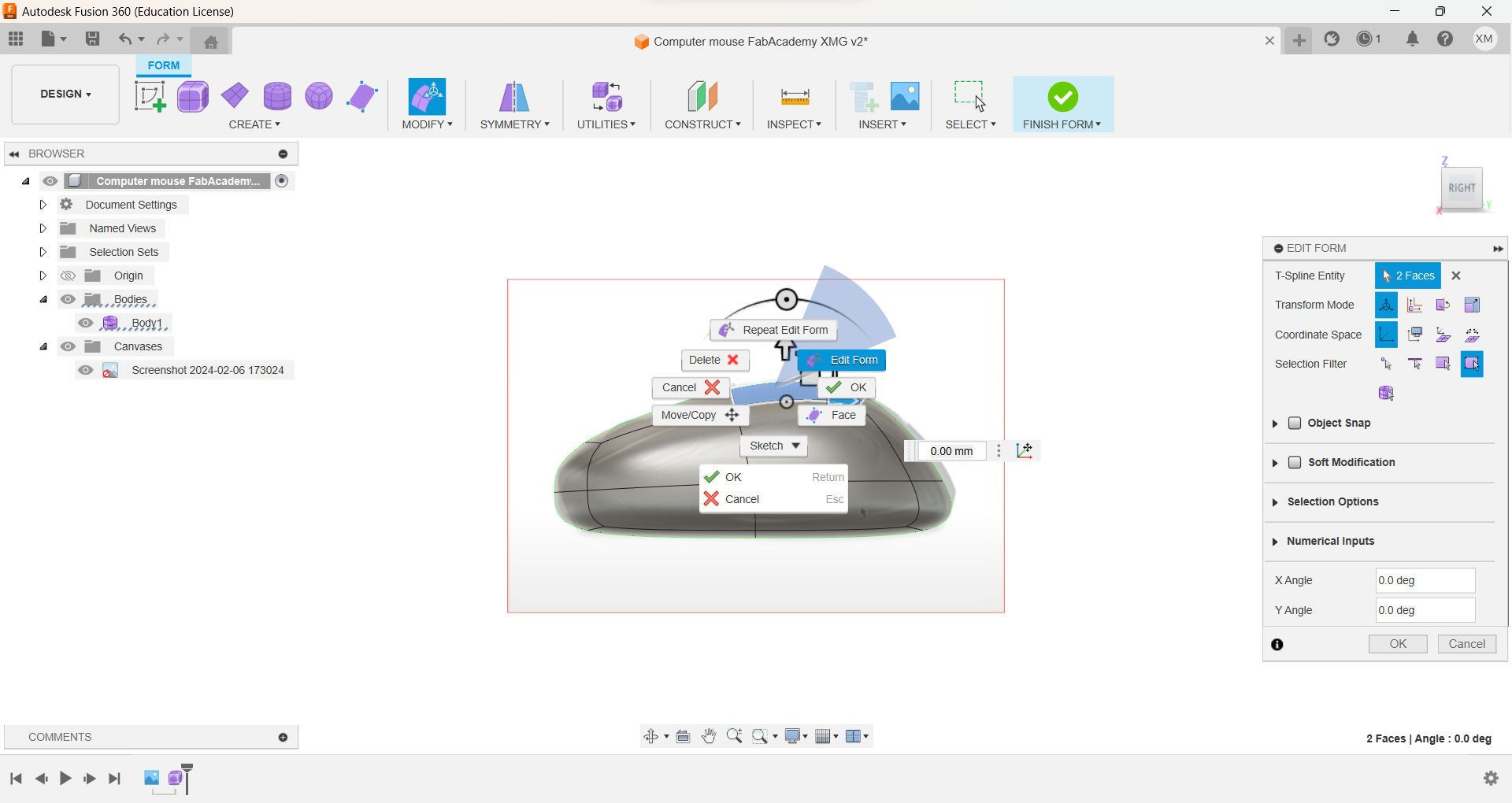
And in the tool bar select the action that you would like to do.I needed to add another line so I used "Insert Edge
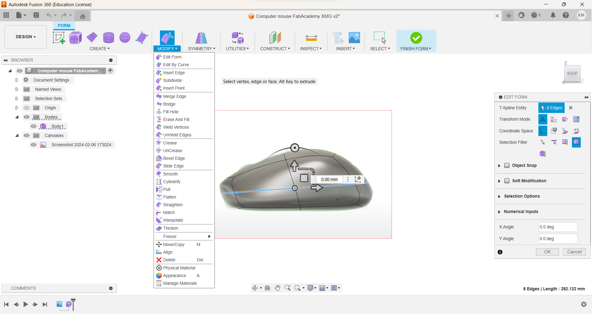
Change planes to give a similar to that of the mouse.
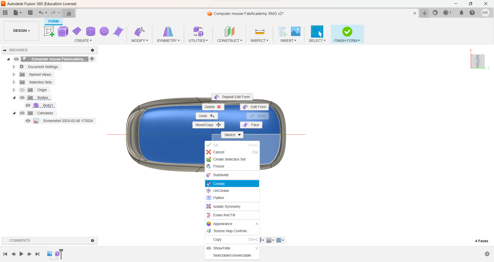
For the bottom part, align the base with "crease",
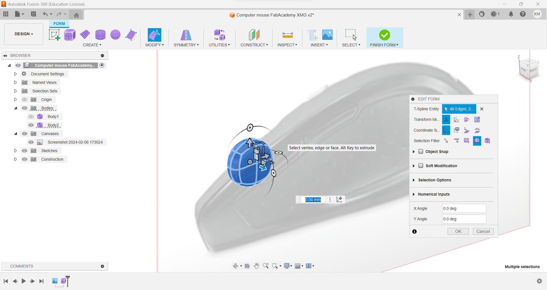
I add another square and round the edges to make the roller. I round them using the same tools and with the coursor I gave them aproximately 40.mm
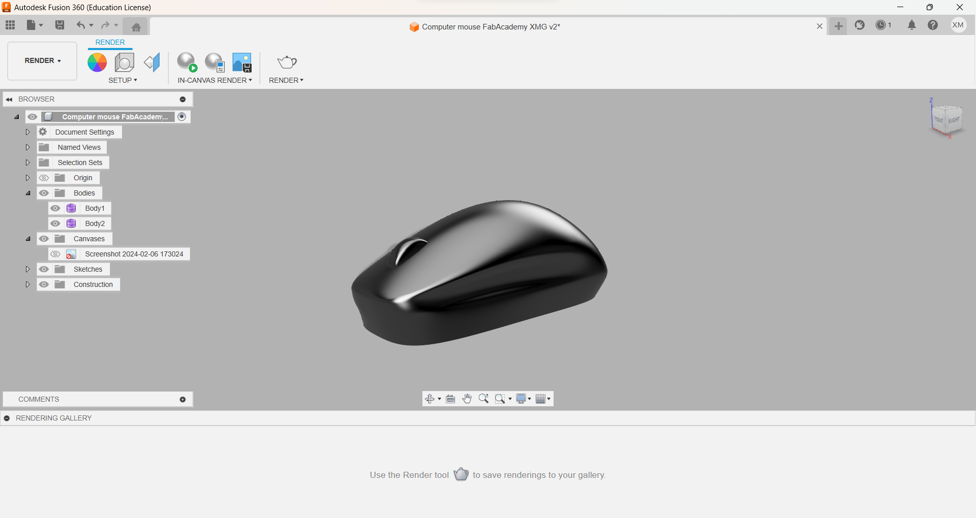
And adjust it to look as desired, At the end, add a material comparison between the plane and the render. You can select the materials changinf=g the mode where it says DESIGN desplay the options and select RENDERING
Save the document as .obj to be able to export it in Figma.
Go to vectary.com to create your account using google chrome and start creating your own renders

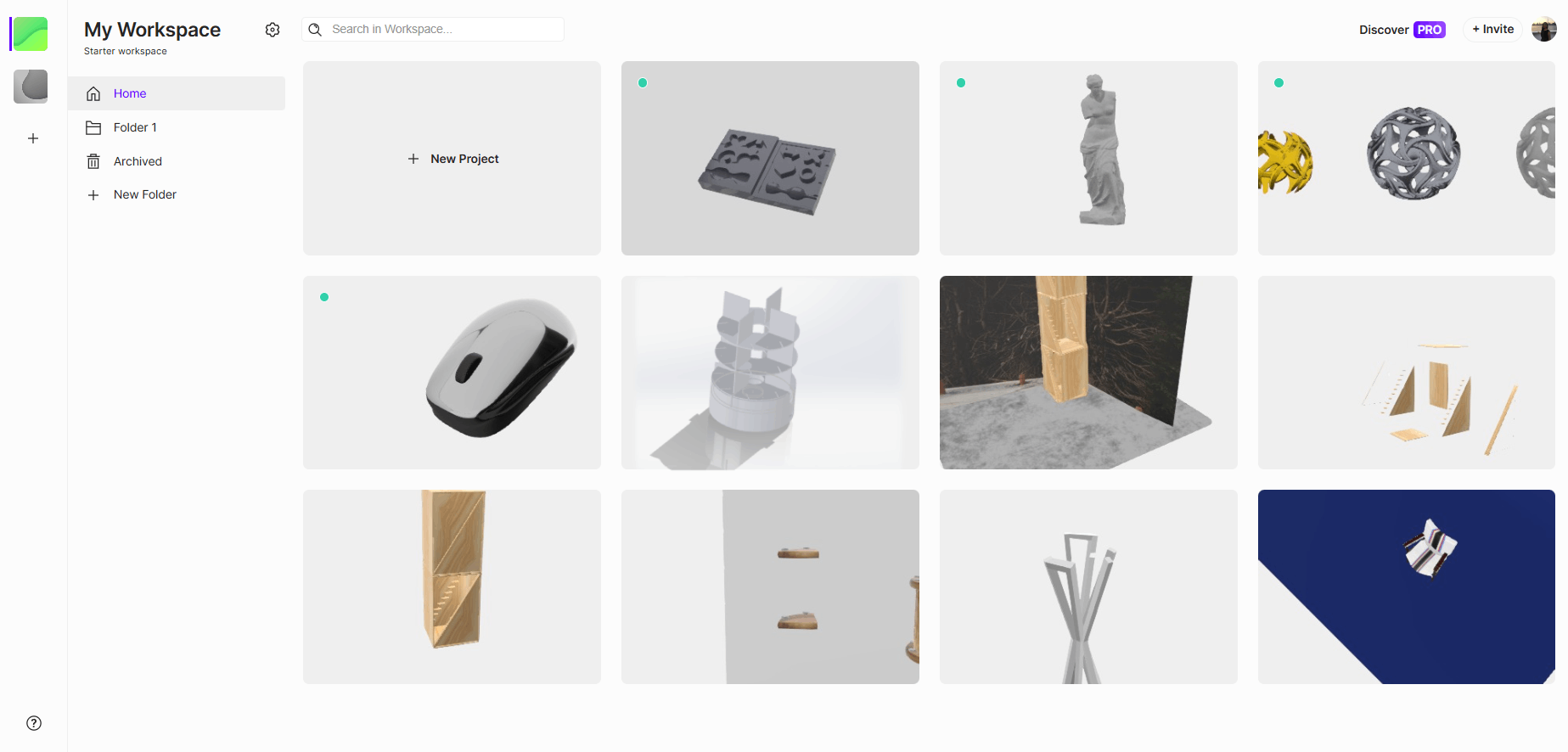
Once you have created your account this is going to be how your feed looks like, you need to click in new project to continue using
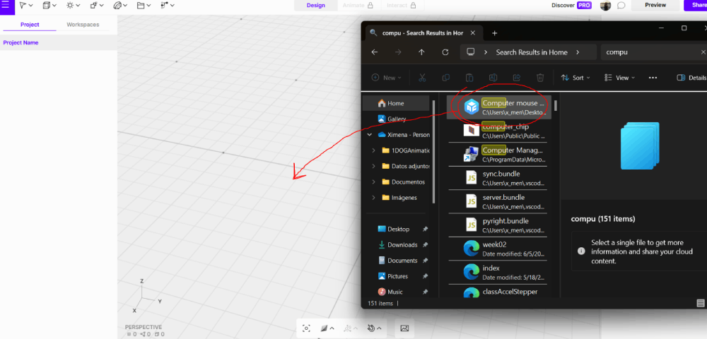
If you already have a model, you can go to your archive and drag the STL document into the blank space. You can check if it was installed correctly by going to the layer display and selecting "Effects" or "Advanced Adjustments."
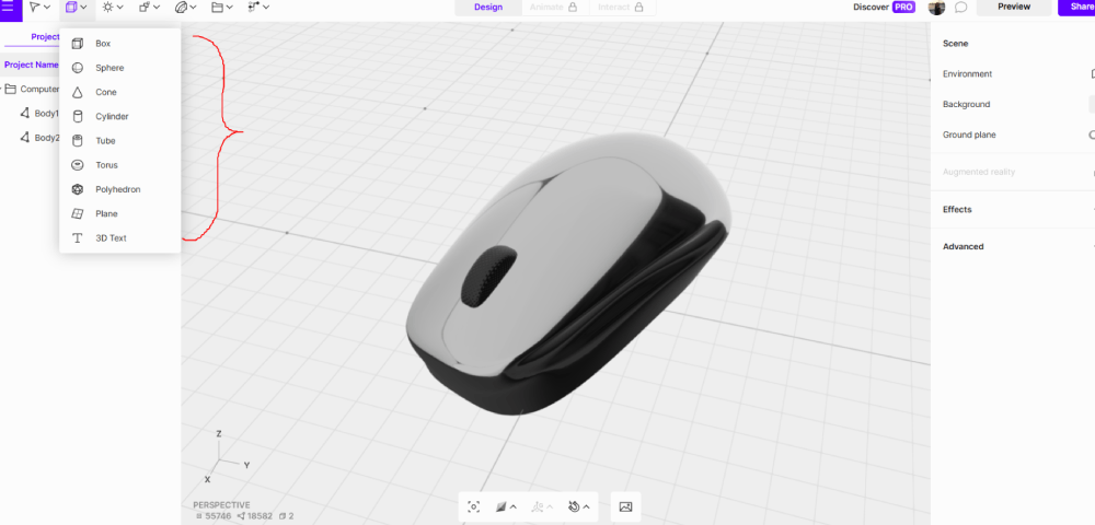
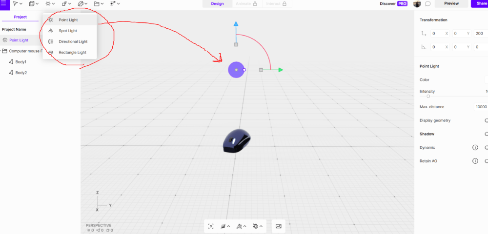
If you want to render from the beginning, there's an option in "Shapes" to create 3D objects such as boxes, spheres, cones, etc.
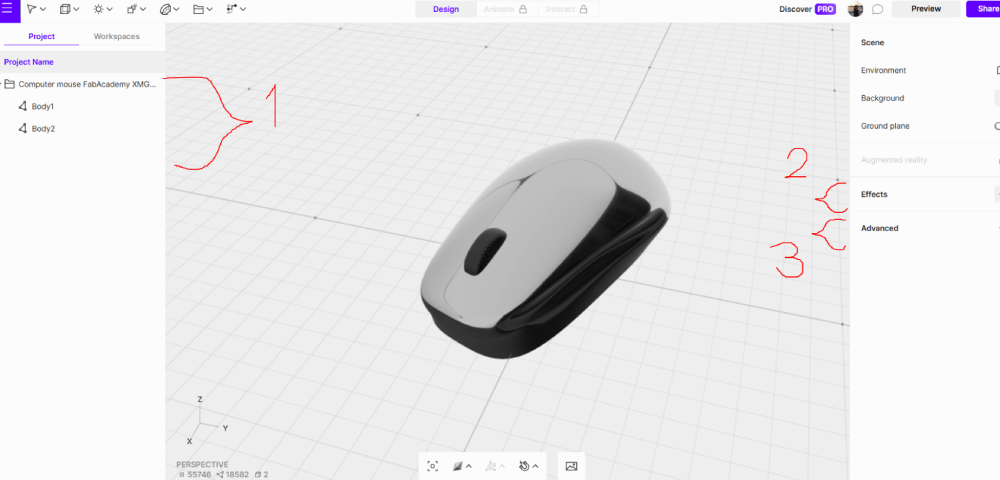
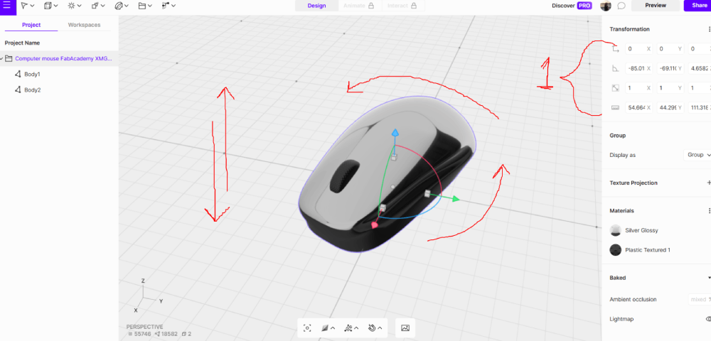
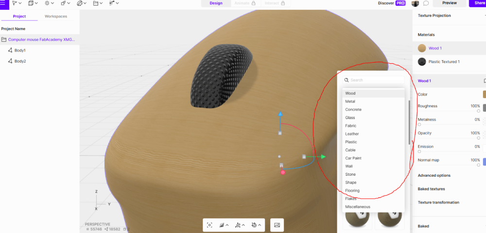
Then, once you click the object, you can rotate or move it up, down, and side to side. In the display on the right, you can see the weight and height of the object. To add or edit texture, you can click on "Effects" and select any texture you like from the library. You can then edit them as you prefer, changing the color, light, and roughness of the material.
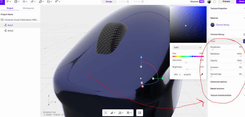
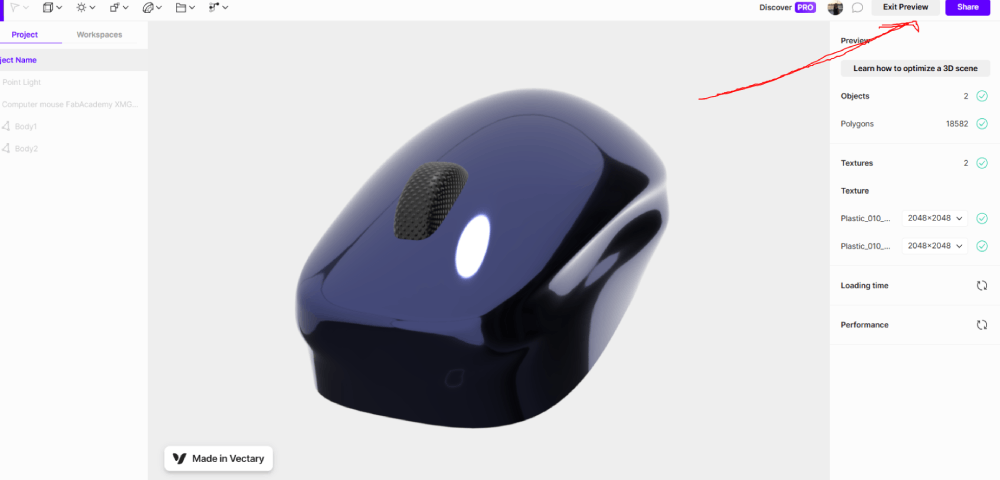
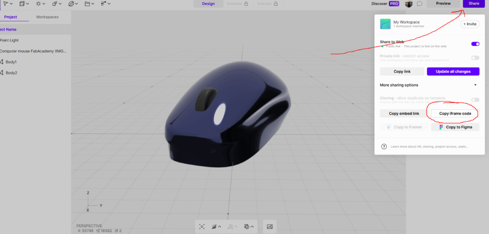
Finally, to get a better look at the material, you can add light using the adjustment tool to achieve the desired appearance. At the end, add a material. To compare the final version, click "Preview." If you want to use the render on your page, exit the preview, click "Share," and copy the iframe code. Paste it in the page and if you do any change click update all changes in the blue boton.
3D Model
Files
Tutorial
Reflection Summary
This week’s experience has underscored the importance of versatility and adaptability in the field of CAD. Each software platform offers its own unique set of tools that cater to different aspects of design and modeling. The ability to switch between platforms, depending on the project requirements, is a skill that I have started to develop.
Moreover, the experience has highlighted the importance of precision and attention to detail in CAD work. Simple tools such as tracing lines or creating patterns require meticulous attention, as they directly impact the quality and accuracy of the final design.
Challenges and Solutions,
One challenge I encountered was mastering the different software platforms introduced this week. Each software has its own learning curve and unique tools. To overcome this challenge, I focused on practicing regularly and watching tutorials to understand the different tools and how they work.
Future Applications
Looking ahead, I am eager to further explore the capabilities of the software platforms introduced this week. This includes mastering advanced features, such as creating animations or simulations in 3D models, and improving my workflow efficiency.
In conclusion, Week 2 of the CAD course has been a foundational experience that has provided me with a solid understanding of digital design tools and methodologies. I look forward to applying these skills in upcoming projects and continuing to expand my knowledge in the field of Computer Aided Design.