Week 04:Electronics Production
Grupal Assigment
Process Recap
PCB Milling at FabLab PueblaThree Mini-Mill models are used for PCB milling. They use high-speed rotary cutters to carve copper-clad substrates based on digital designs, ensuring precise pathways for circuits.
Mini Mill Components- Front Cover: Protective shield for user safety
- Power Button: Main power switch
- Spindle Head: Houses spindle motor for milling
- Working Table: Surface for securing PCB material
Specifications for the SRM20 model are provided, including operational travels, loadable workpiece weight, operation speed, etc.
Compatible MaterialsVarious materials can be used with laser cutters, including modeling wax, foam, acrylic, etc.
Safety Guidelines- Single Operator: Equipment must be operated by one person at a time
- Cable Handling: Proper handling of cables
Two tools, a 15-degree V-bit for engraving and a 0.8 mm diameter two-flute end mill for cutting, are used for precision in PCB milling.
Parameters for PCB MillingDrill hole size, material choice (FR1 or FR4), minimum clearance, minimum trace width, and number of layers are critical factors to consider for successful PCB milling.
Planned ParametersSpecific parameters for milling operations, including tool types, cut depth, cut speed, and spindle speed, are outlined.
Image Transformation and SoftwareMODS software is used to transform images into .rml files compatible with the SRM20 Mini-Mill.
Ease of UseDespite initial complexity, the process is straightforward, with clear steps outlined for achieving desired results.
Toolpsth process
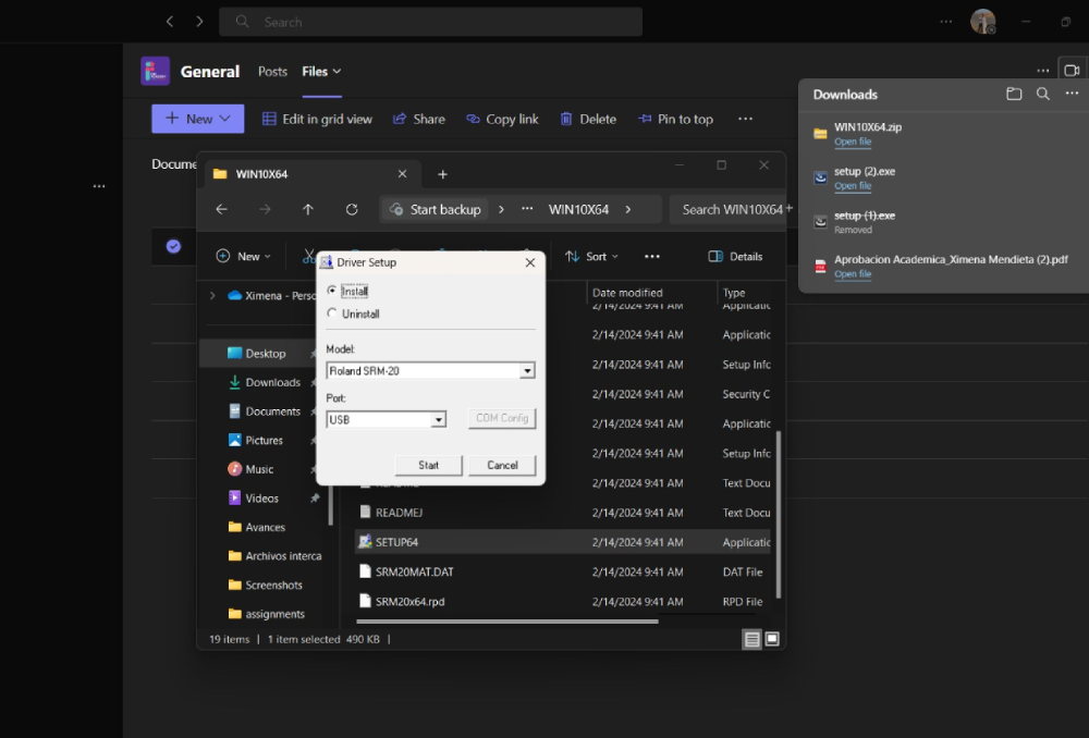
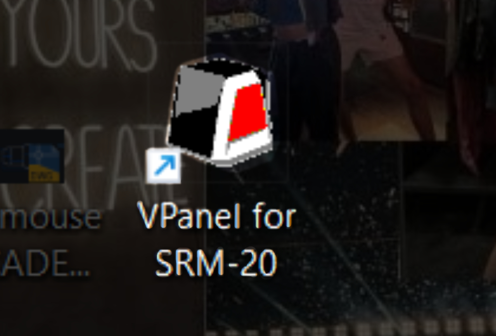
ROLAND SRM-20 InstallationFirst I had to instal the program I dowloaded al the links for the software, compatible for the cutter, Its important to say that this specific software is only compatible with windows devices. I accepted all and cliclk in Install option, if everithing works it sold appear a logo like this one in your desktop
Document Creation:
- Navigate to (Mods) and follow the specified process to open the web program.
- Upload the files Trace and Cut in PNG format, ensuring to invert the image for cutting.
- Adjust parameters and press "Calculate" to automatically save the files.
- Open the program and click "Cut," first tracing and then cutting.
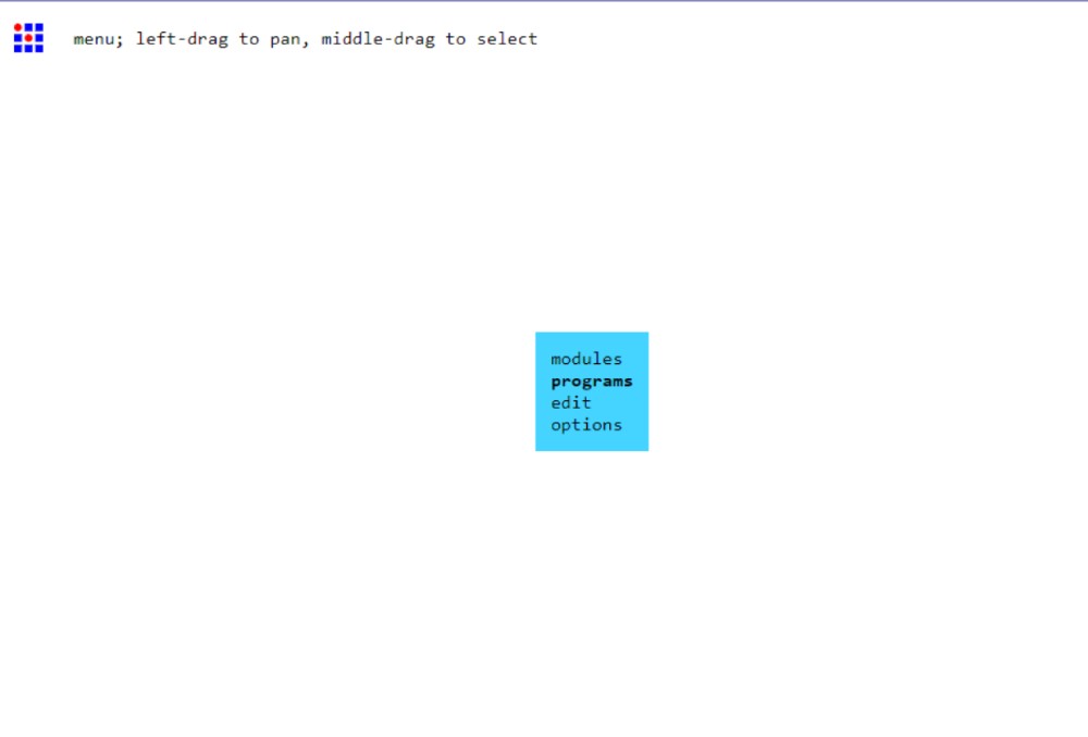
For this part you need to go to (Mods) and follow this exact process to open the web program
First click "PROGRAMS"
Then "OPEN PROGRM"
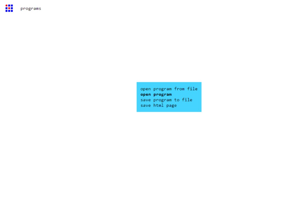
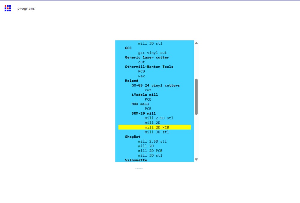
Scroll down till you find Roland >SRM- 20 mill > mill 2D PCB.
You need to upload the files Trace and Cut and in PNG and only for Cut invert the image like I show in the following images
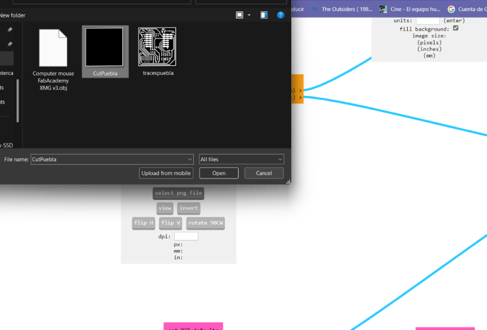
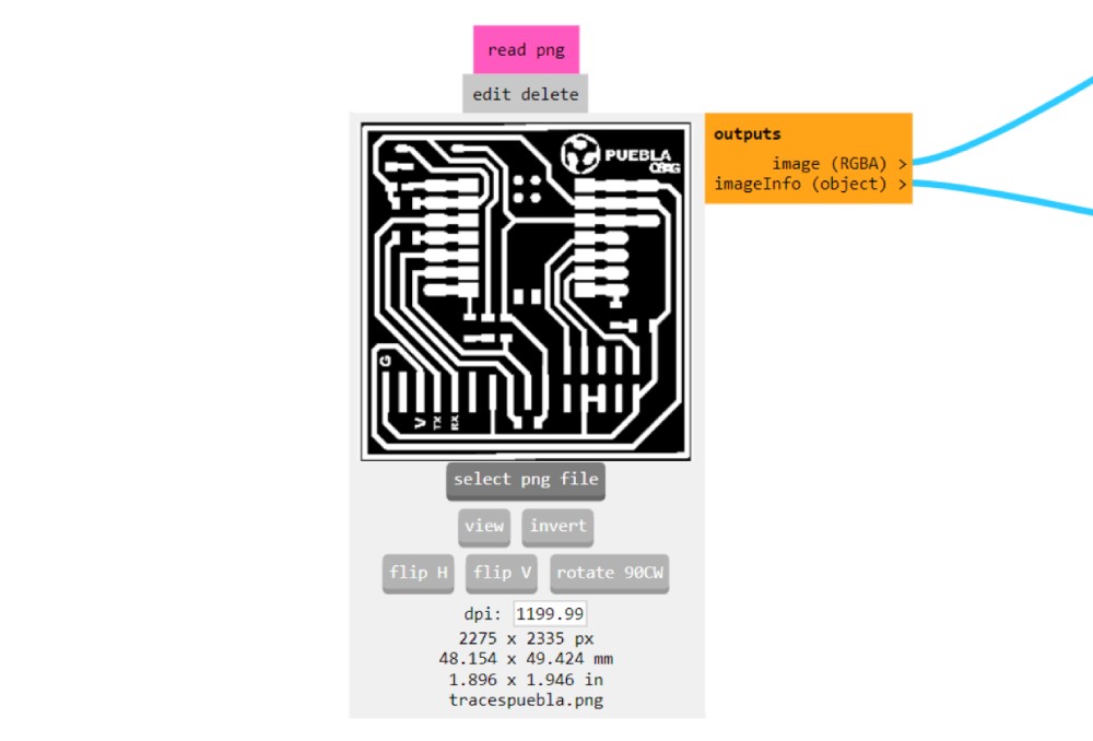
Once you have selected our file remember thet white is the color that remains and black is where the machine is going to cut.
If necessary click invert
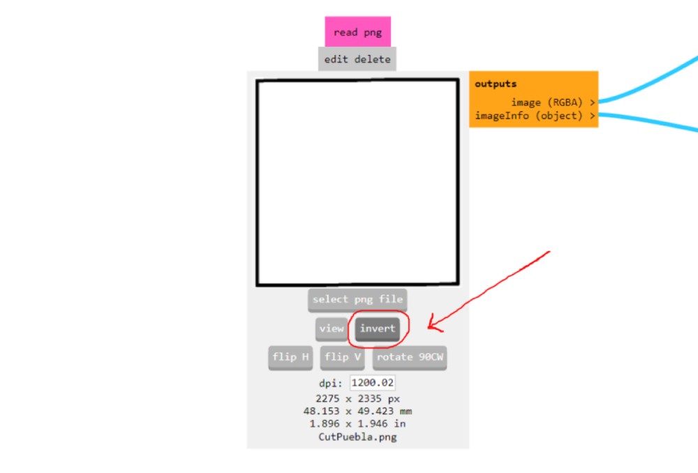
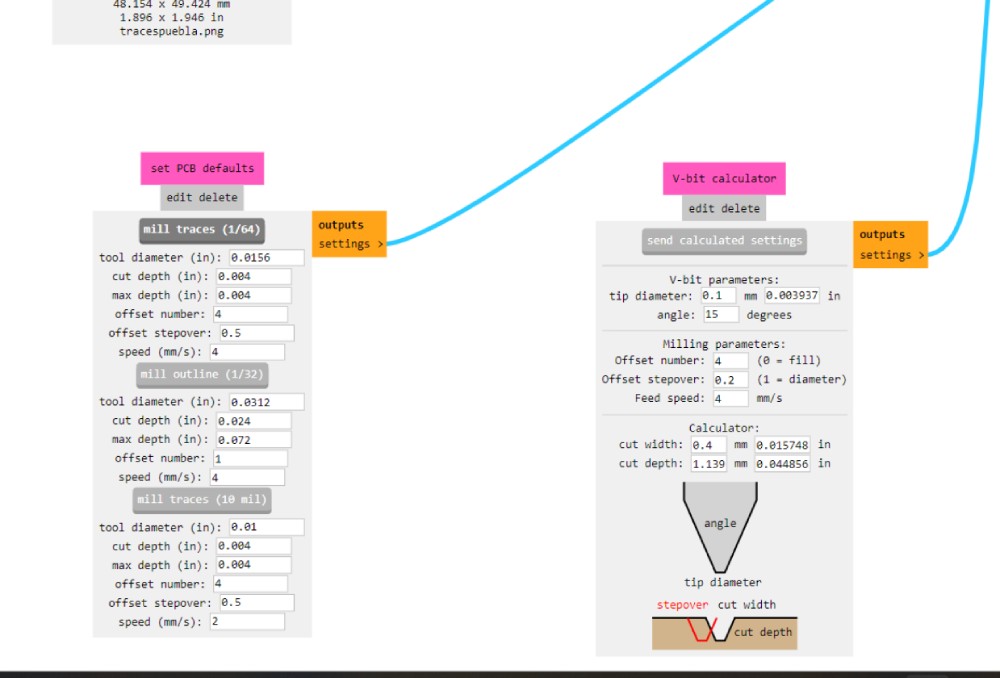
Then change the parameters and press calculate to automaticlly save the files.
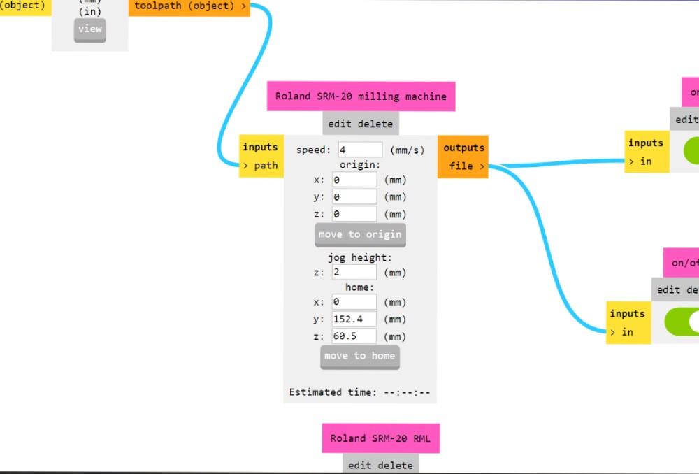
Speed I leave it at 4 and make sure x,y,z are in 0
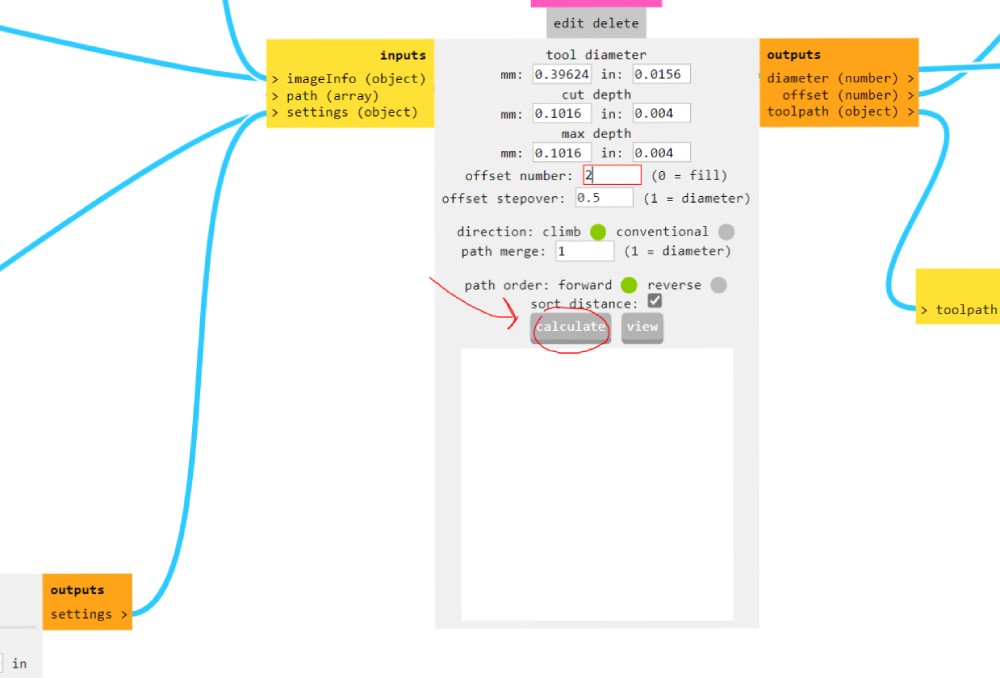
I personally used offset 2 due 1 layer was to skinny and it can cause a false conection with other components if I didnt sold it carefully and 3 was to thickk and did not leave enough space for the components
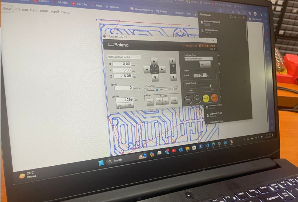
Once you locate the acrhives open the program and click cut .
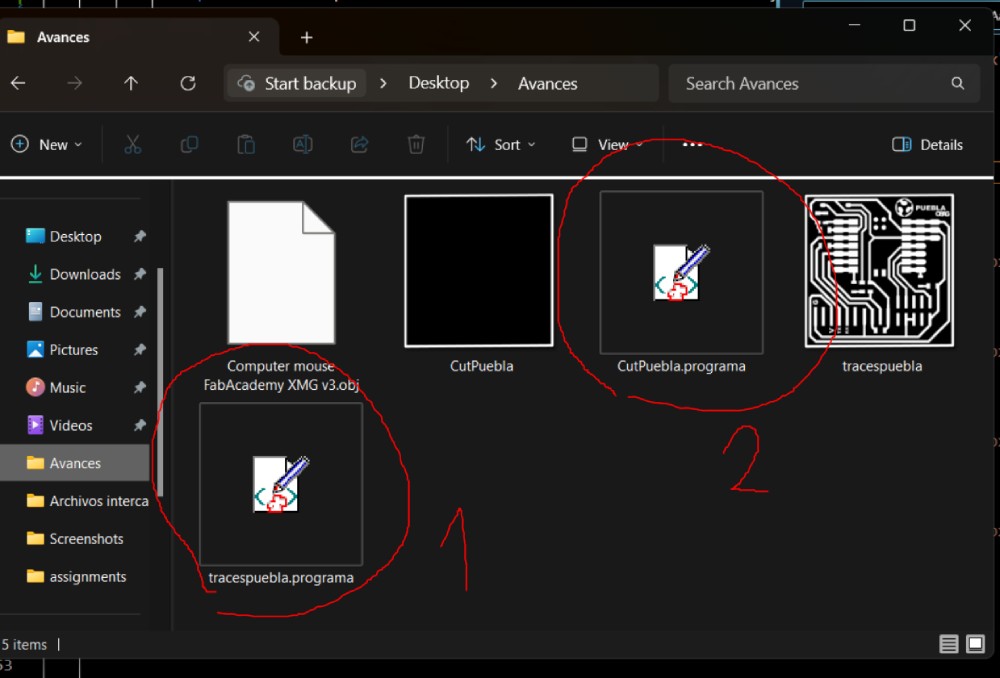
To add the files sellect the button Cut and add files, if you had previouse files click "delete all" and add the new one
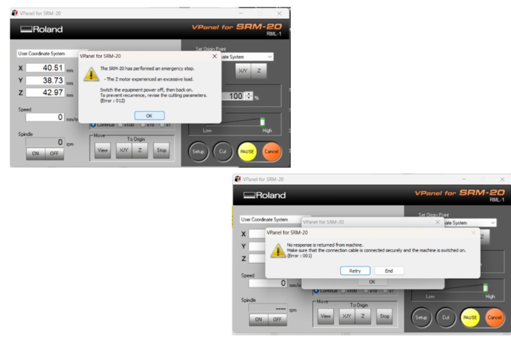
First trace and then cut **IF ANY OF THIS ERRORS APPEAR*** Select OK and RETRY and for the machine to continue the cut or shut down de softwar, desconect the cable and redo all this process
Machine Cut:
- Position the machine with the bottom facing away from the computer.
- Insert the spare piece onto the copper table, secured with double-sided tape and screws.
- Utilize software controllers if needed to adjust machine position.
- Use a V-shaped tool for tracing and a Small Cutter for cutting, as per group practice.
Cut Tools
- V Cutter Bit, PCB, Engraving, Router Milling Cutter Degrees Cnc
- Flat End Mill Cutters 1, 2, 3.175mm Pcb, Cnc Router
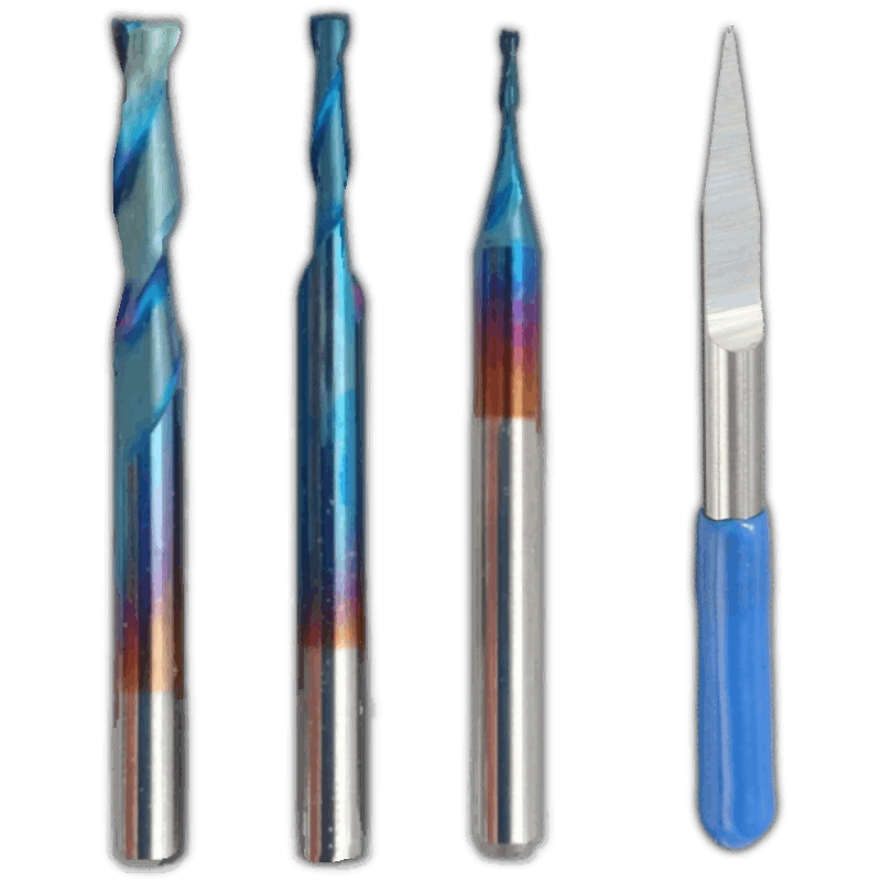
Package cutters
Turn the machine with the bottom behind the computer, then enter the spear pice with the copper table already pasted with doble tape and place it in the machine with screws. If the machine is getting in the way you can move it with the contolers of the software. For the trace you need a tool in V and for the Cut a Small Cutter as in the grupal practice.
Make sure the machine is on if the button has the light in green
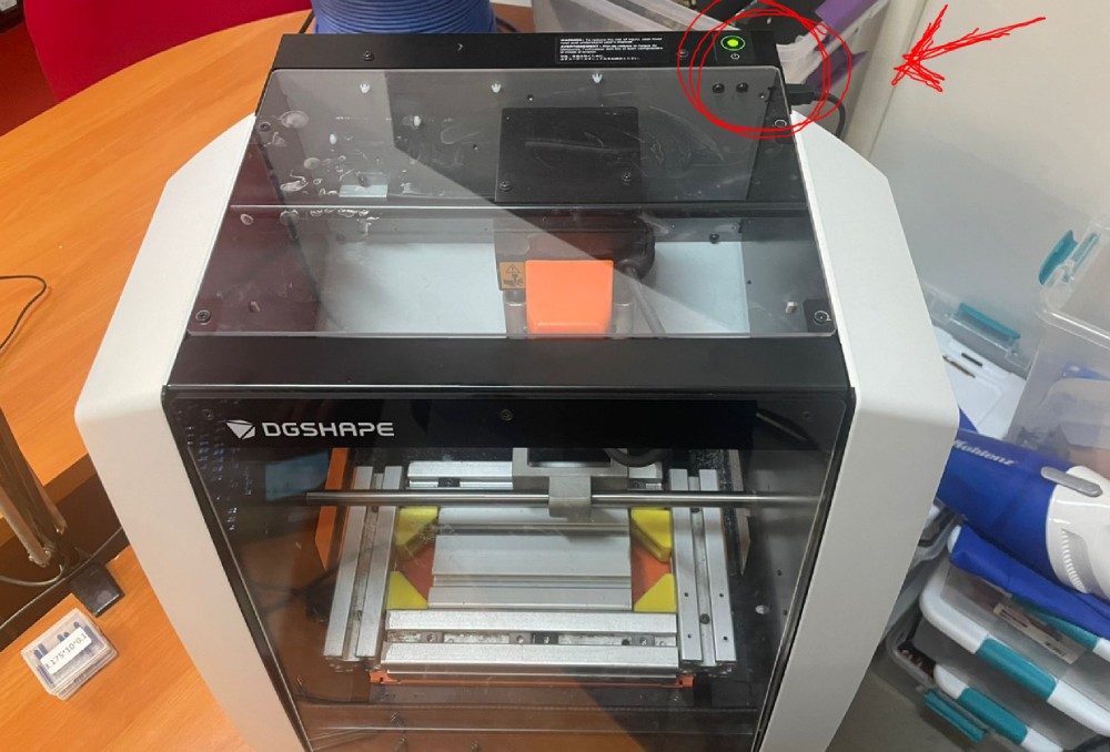
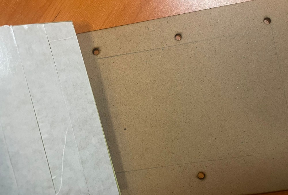
Before cutting the board we pasted the table in a sacrifice bed wich Ill be adding at the end just to make sure the copper tanle wont move while it is cutting
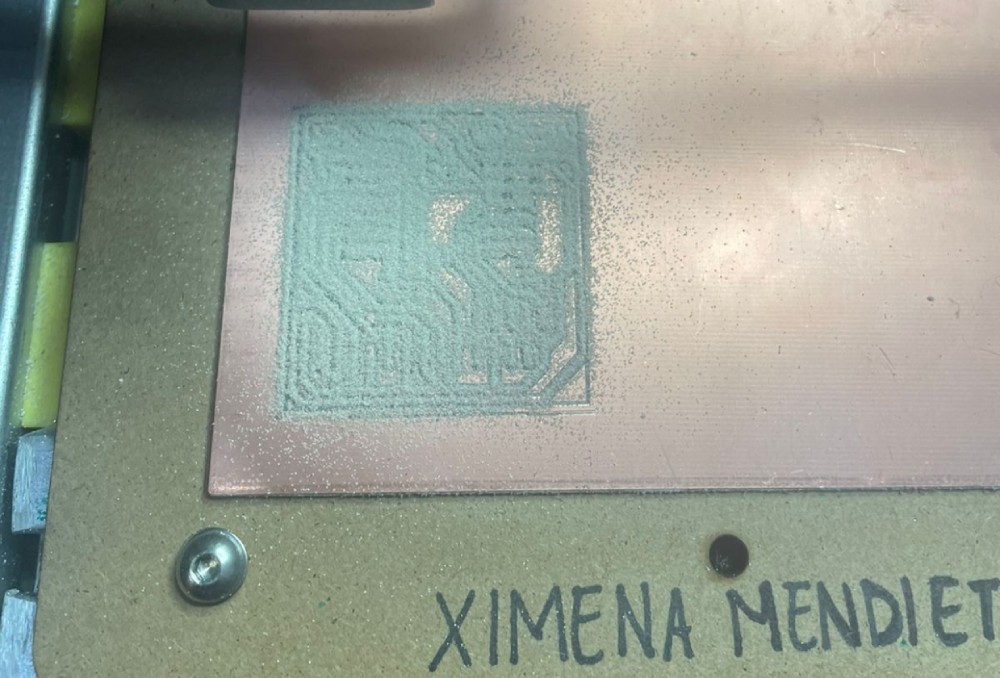
Be careful not to bread near the piece due the little dust is really toxic, If everithing went right this is how the final PCB looks like.
Components:
- 3 LEDs
- 1 Push button
- 1 Xiao RP2040
- 1 of 6 & 2 of 5 Resistors
| Qty | Description |
|---|---|
| 3 | Leds |
| 1 | Push bottom |
| 1 of 6 & 2 of 5 | Resistence |
| 1 | Xiao |
Soldering:
- Take apart the piece and solder without the leftover board, or solder first and then remove the piece.
- Use masking tape to prevent copper from touching metal components.
Personally I take the pice out just to make sure it was detachable and then I place it back and solder with the table.
Important to put masking tape so that the copper does not touch the xioms metal components
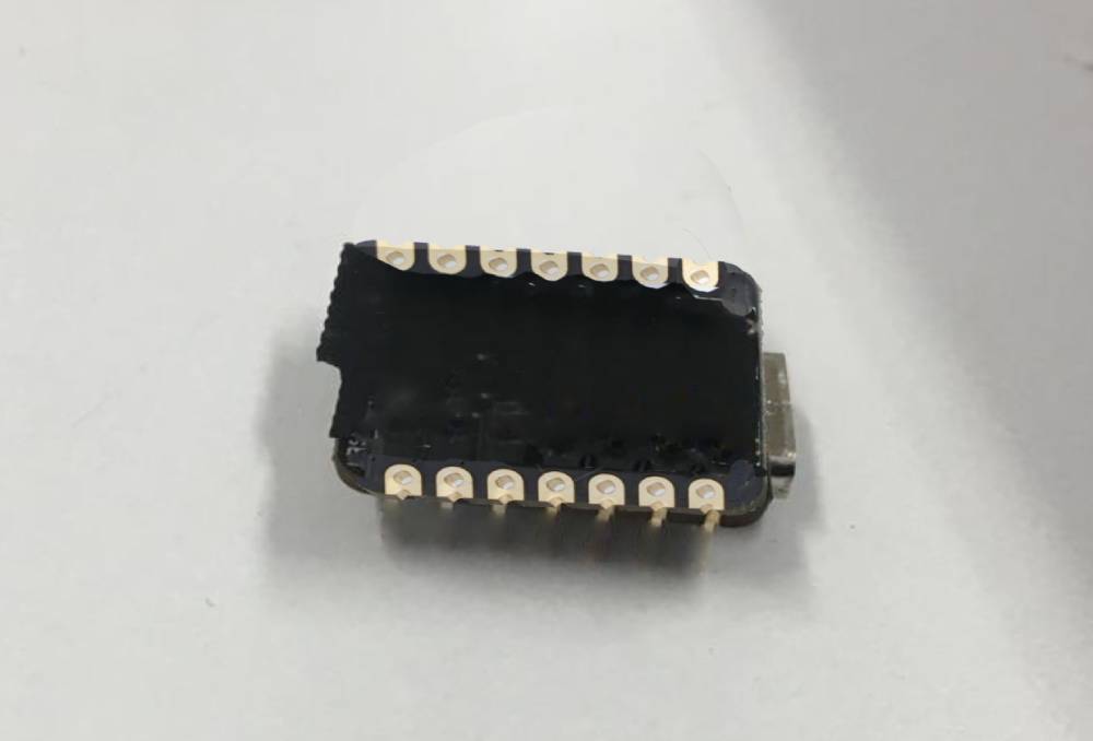
How to prevent Troubleshooting and Adjustments:
- Inspect soldered components under a microscope for any issues.
- Address any non-contacting parts and reinforce connections if necessary.
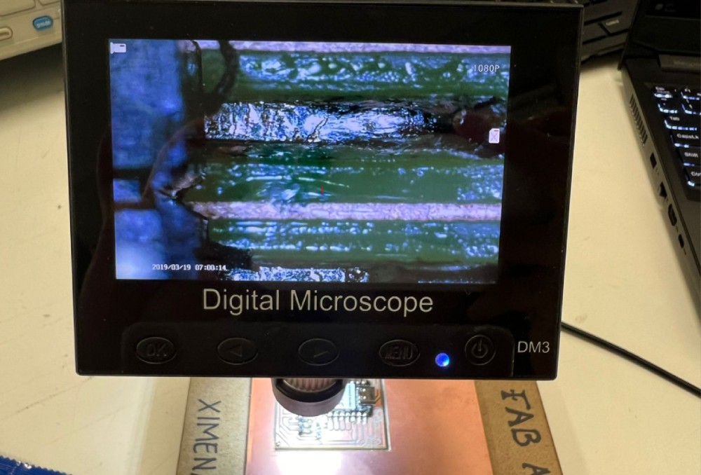
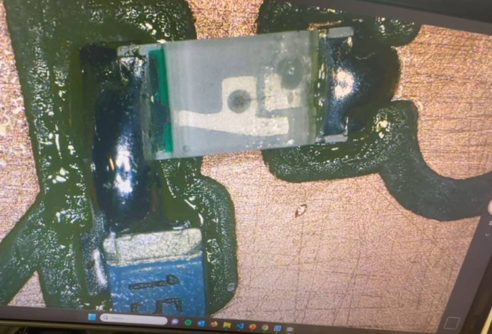
Once I solder every component I took a closer look with the microscope just to find there were parts that did not toach the board. So I tried to retouch them and accidently I separated the resisence from the final board but thankfully some pices were not directly conected to others so I reforce the pice and everithing worked fine.
Programming:
- Now is time to download the code onto a computer and connect it using a USB- C cable .
-
STEPS:
- Open Arduino
- File > Preferences
- Paste this link https://github.com/earlephilhower/arduino-pico/releases/download/global/package_rp2040_index.json in Additional boards manager URLs
- Tools > Board > Board Manager
- Search for RP2040 and Install
- Select Board and Port
- Upload your own code
Download or copy the example code.
CODE
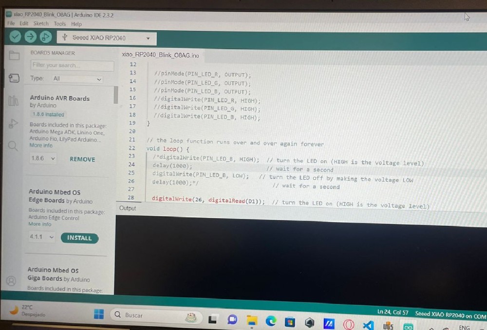
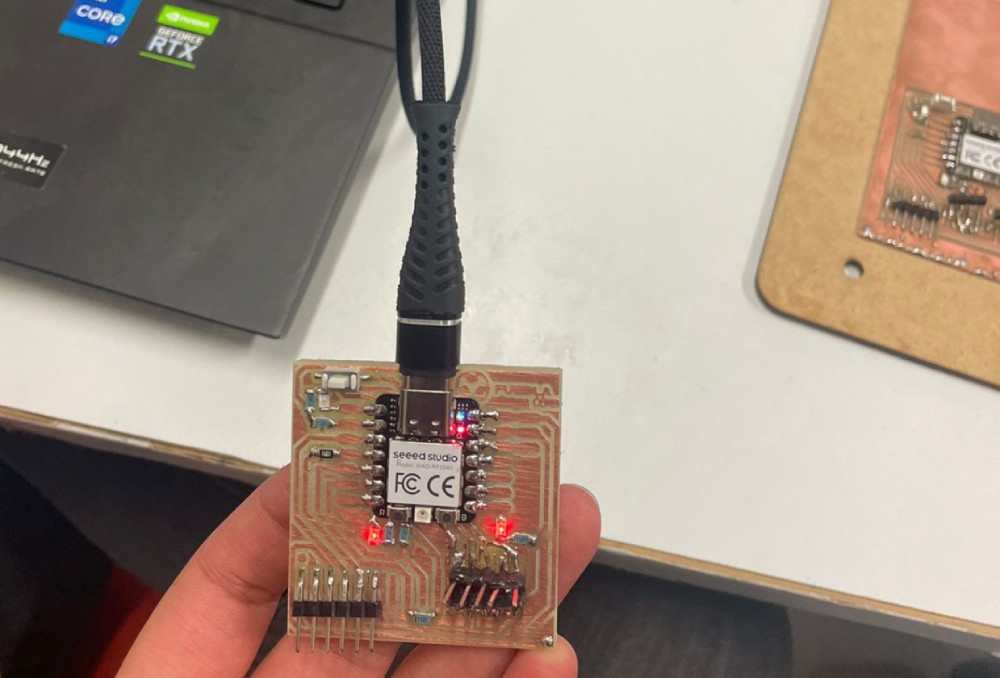
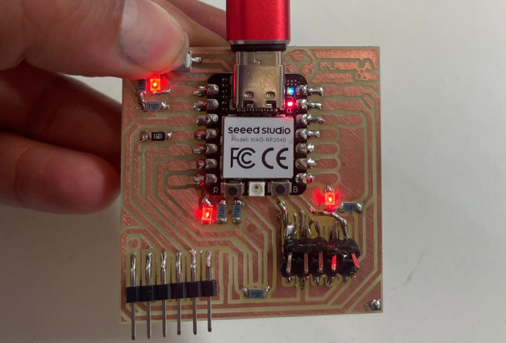
This is a code given by instructor Huber Giron. What it does it a blinking the LEDs from the bottom every second and when I push the button the third LED start blinking at the same rate.
Final Result
Files
Links
Reflection Summary
This week, I focused on the process of milling a PCB (Printed Circuit Board) using the Roland SRM-20 machine, and then assembling and programming the board. The key steps involved software installation, document creation, machine cutting, component soldering, and troubleshooting.
The most significant part was learning to create and prepare the PCB design files, operate the milling machine, and carefully solder the components to ensure proper functionality. Additionally, programming the board using the downloaded code provided valuable insights into integrating hardware and software.
Challenges and Solutions
One of the biggest challenges was ensuring the precision of the cuts and the proper attachment of components. The software used was only compatible with Windows, which required specific setup steps. To overcome the challenges, I carefully followed the steps to create and adjust the design files in the Mods software, ensuring the correct parameters for cutting. Additionally, I used masking tape during soldering to prevent short circuits and inspected my work under a microscope to fix any loose connections.
Future Applications
The skills gained this week are crucial for creating custom electronic circuits and integrating them into various projects. Understanding the PCB milling process, from design to assembly and programming, provides a solid foundation for future electronics projects. These skills are invaluable for developing prototypes, experimenting with new designs, and troubleshooting hardware issues efficiently.
