In week 6, I explored programming the Seeed XIAO RP2040. Since it was almost my first time programming, it took a lot of work and time. Finally, I accomplished making my board perform some simple tasks, which allowed me to understand the principles of programming.
Browse through the datasheet for your microcontroller
Compare the performance and development workflows for other architectures
Document your work to the group work page and reflect on your individual page what you learned
Individual assignment:
Write a program for a microcontroller development board to interact (with local input &/or output devices) and communicate (with remote wired or wireless devices)
Learning Outcomes
Implement programming protocols
Results: Embedded Programming
As an architect, I had not programmed anything until now. My first approach to programming was in week 4 when I programmed the Quentorres so that the LED turned on. Therefore, this week's assignment seemed like a great challenge for me.
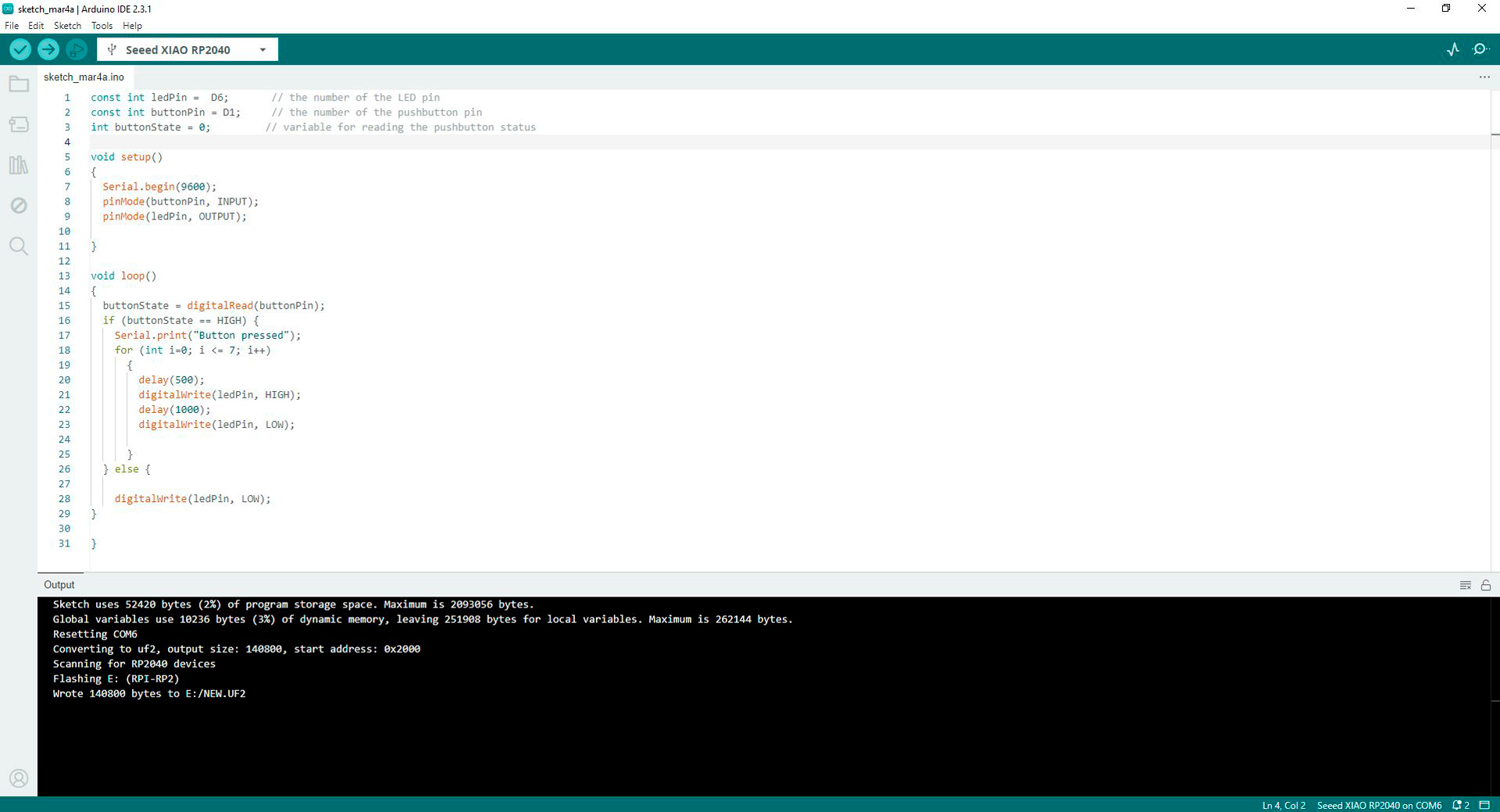
First of all, I did my first programming tests with the XIAO RP2040, a LED and a button connected on a breadboard. I did this because I was afraid of damaging some PCB components that were so difficult to find in my country. After gaining confidence, I programmed the microcontroller in the Quentorres PCB so after pressing the button the LED would light up 8 times and send a message to the Arduino IDE serial monitor. For accomplish this, I used this guide and help from my colleague Ronal Vilca. I used this code in Arduino IDE:
const int ledPin = D6;     // the number of the LED pin
const int buttonPin = D1;  // the number of the pushbutton pin
int buttonState = 0;       // variable for reading the pushbutton status

void setup()
{
  Serial.begin(9600);
  pinMode(buttonPin, INPUT);
  pinMode(ledPin, OUTPUT);

}
void loop()
{
  buttonState = digitalRead(buttonPin);
  if (buttonState == HIGH) {
  for (int i=0; i<=7; i++)
  {
	delay(500);
	digitalWrite(ledPin, HIGH);
	delay(1000);
	digitalWrite(ledPin, LOW);

  }
} else {

  digitalWrite(ledPin, LOW);
}

}
Code in Arduino IDE for programming button and LED in Quentorres
Code being upload to XIAO RP2040 for programming button and LED in Quentorres
Data send to the serial monitor from the button on Quentorres once it is pressed
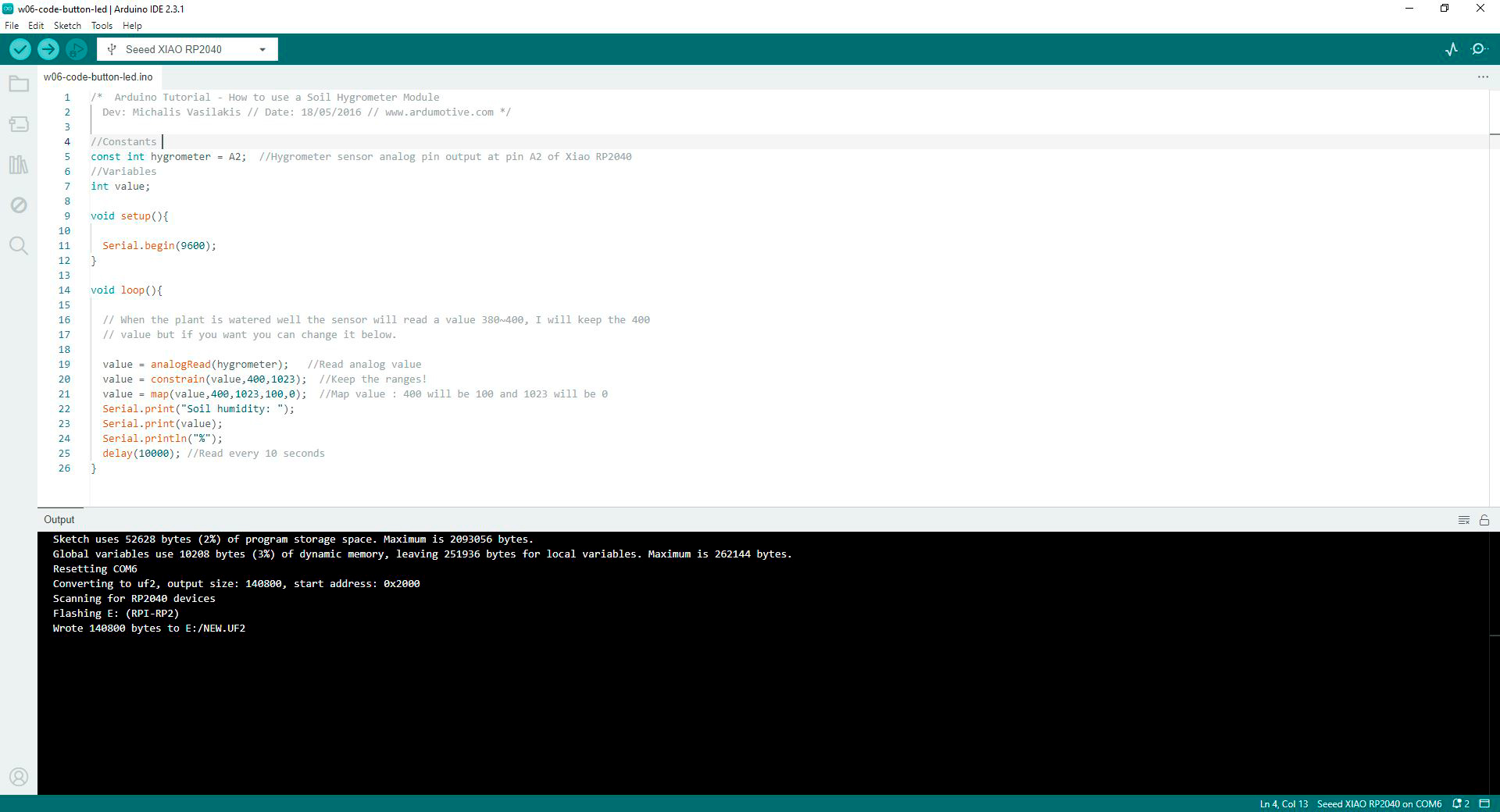
I felt very happy and motivated when the code worked. So I decided to program a soil moisture sensor based on this code. Every 10 seconds the measured humidity percentage of a pot with soil and a lemon tree would appear on the Arduino IDE serial monitor. After breaking a component of the Quentorres (because it was desoldered), adjusting loose wires, and several tests, the programming worked. I used this code in Arduino IDE:
// constants
const int hygrometer = A2;  // hygrometer sensor analog pin output at pin A2 of XIAO RP2040
// variables
int value;

void setup(){

  Serial.begin(9600);
}

void loop(){
  // when the plant is watered well the sensor will read a value 380∼400, I will keep the 400
  // value but if you want you can change it below.

  value = analogRead(hygrometer);     // read analog value
  value = constrain(value,400,1023);  // keep the ranges
  value = map(value,400,1023,100,0);  // map value: 400 will be 100 and 1023 will be 0
  Serial.print("Soil humidity: ");
  Serial.print(value);
  Serial.println("%");
  delay(10000);                       // read every 10 seconds
}
Code in Arduino IDE for programming the hygrometer in Quentorres
Code of hygrometer well programmed
There was very intense work this week that gave its results with this latest exploration. I still feel that I have a long way to go in the world of programming: the vast majority of the code I generated was based on codes I found in Arduino IDE libraries, the internet, and colleagues who helped me. Still, this week represented a great learning for me.
Group Assignment: Datasheet Comparison for Diverse Architectures
For this group task, we decided to work on a collaborative file in which we would compare various microcontrollers and their characteristics.
Comparative chart about diverse architectures
As a group, we worked on this comparative chart of the ATTINY412, SAMD11C, XIAO RP2040, XIAO ESP32-C3 and ATTINY 1624 microcontrollers based on the following features: architecture, clock frecuency, flash memory, RAM memory, communication interfaces, integrated peripherals, development tools and compatibility with boards.
PDF Viewer
Conclusions:
Architecture: Greater capacity (32bits) = SAMD11C, XIAO RP 2040 and XIAO ESP 32-C3. All the microcontrollers utilize the Harvard architecture.
Clock frecuency: Higher clock frecuency = XIAO RP2040 and ESP32-C3
Flash memory: Greater data transfer = XIAO RP2040 and ESP32-C3
RAM Memory: Greater memory = XIAO RP2040 and ESP32-C3
Communication interfaces: The most versatile serial communication protocols belong to the XIAO ESP32-C3
Integrated peripherals: The most versatile integrated communication protocols belong to the XIAO ESP32-C3
Power consumption: SAMD11C has the lowest energy consumption, which implies a greater shelf life. All other microcontrollers studied consume from 3.3V to 5V (except for the Atiny412 consumed from 3V). Energy consumption will depend on its use.
Development tools: Microcontrollers who use free languages are XIAO RP2040 and ESP32-C3
Compatibility with boards: Microcontrollers are compatible with various boards. The choice will depend on its use.
Working with my Fab Academy colleagues in a collaborative way was very interesting. Each one researched about different microcontrollers and we shared our findings and discuss about them for learning about various architectures.
Collaborative grupal assignment
Individual Assignment: Programming my Board
I am a newbie to programming. During week 4 I programmed Quentorres so that the LED turned on and that has practically been my only approach to that area. Therefore, I felt that I needed to understand the code first, before understanding the connections on the board itself. To do this, I reviewed this guide, and fab xiao documentation. Then, I realized that I was afraid of ruining my Quentorres (which cost me so much work to finish). So, I changed my approach: I used a breadboard and made some connections with XIAO RP2040, an input (button) and an output (LED) for startign playing with coding.
Understanding Programming
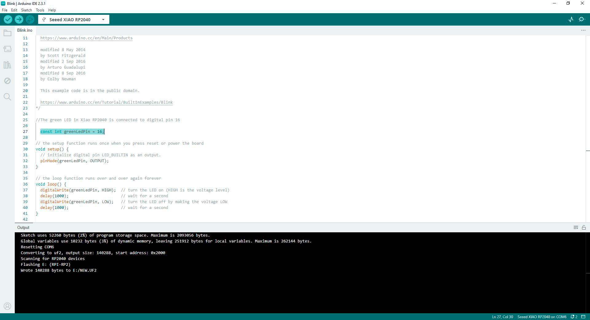
First, I tested what I could do only on the XIAO RP2040. Having already loaded the blink programming during week 4 on the microcontroller (the programming remains enabled until another one is uploaded), I open the blink code in a new sketch in Arduino IDE. The path is: file - examples - basics - blink. I wanted the green LED in the microcontroller to blink, so I asked ChatGPT with this prompt: I want to make green LED in XIAO RP2040 to blink, modify the following code an then pasted the basic blink code in Arduino IDE library. According to ChatGPT answer, I added from lines 25 to 28 a constant for pin 16 (green LED on XIAO RP2040) which is the one I wanted to turn on and off, in addition to the corresponding description. It worked. I used this code in Arduino IDE:
//The green LED in XIAO RP2040 is connected to digital pin 16

  const int greenLedPin = 16;

//The setup function runs once when you press reset or power the board

void setup()  {
  //Initialize digital pin LED_BUILTIN as an output
  pinMode(greenLedPin, OUTPUT);
}

//The loop function runs over and over again forever
void loop()  {
  digitalWrite(greenLedPin, HIGH);  //Turn the LED on (HIGH is the voltage level)
  delay(1000);                      //Wait for a second
  digitalWrite(greenLedPin, LOW);   //Turn the LED off by making the voltage LOW
  delay(1000);                      //Wait for a second
}
Code in Arduino IDE for programming green LED in pin 16 on XIAO RP2040
Green LED in pin 16 on XIAO RP2040 well programmed
Then, I modified the values at lines 38 and 40 so that the on and off time changes: now the LED turns on for 5 seconds and turns off for half a second. It worked. I used this code in Arduino IDE:
//The green LED in XIAO RP2040 is connected to digital pin 16

  const int greenLedPin = 16;

//The setup function runs once when you press reset or power the board
void setup()  {
  //Initialize digital pin LED_BUILTIN as an output
  pinMode(greenLedPin, OUTPUT);
}

//The loop function runs over and over again forever
void loop()  {
  digitalWrite(greenLedPin, HIGH);  //Turn the LED on (HIGH is the voltage level)
  delay(1000);                      //Wait for a second
  digitalWrite(greenLedPin, LOW);   //Turn the LED off by making the voltage LOW
  delay(1000);                      //Wait for a second
}
Code in Arduino IDE for programming green LED in pin 16 on XIAO RP2040 with time changed
Green LED in pin 16 on XIAO RP2040 code with time changed
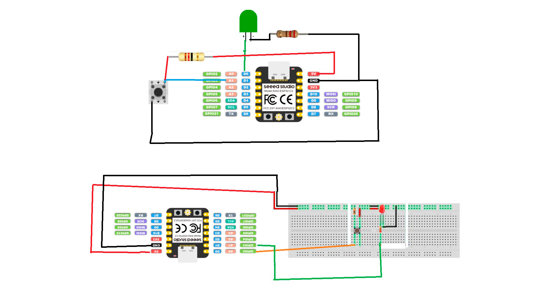
Then, I built the breadboard with the XIAO RP2040, an input (button) and an output (LED). To achieve this, I follow this guide, and my colleague Ronal Vilca helped me.
Making my first connections on a breadboard
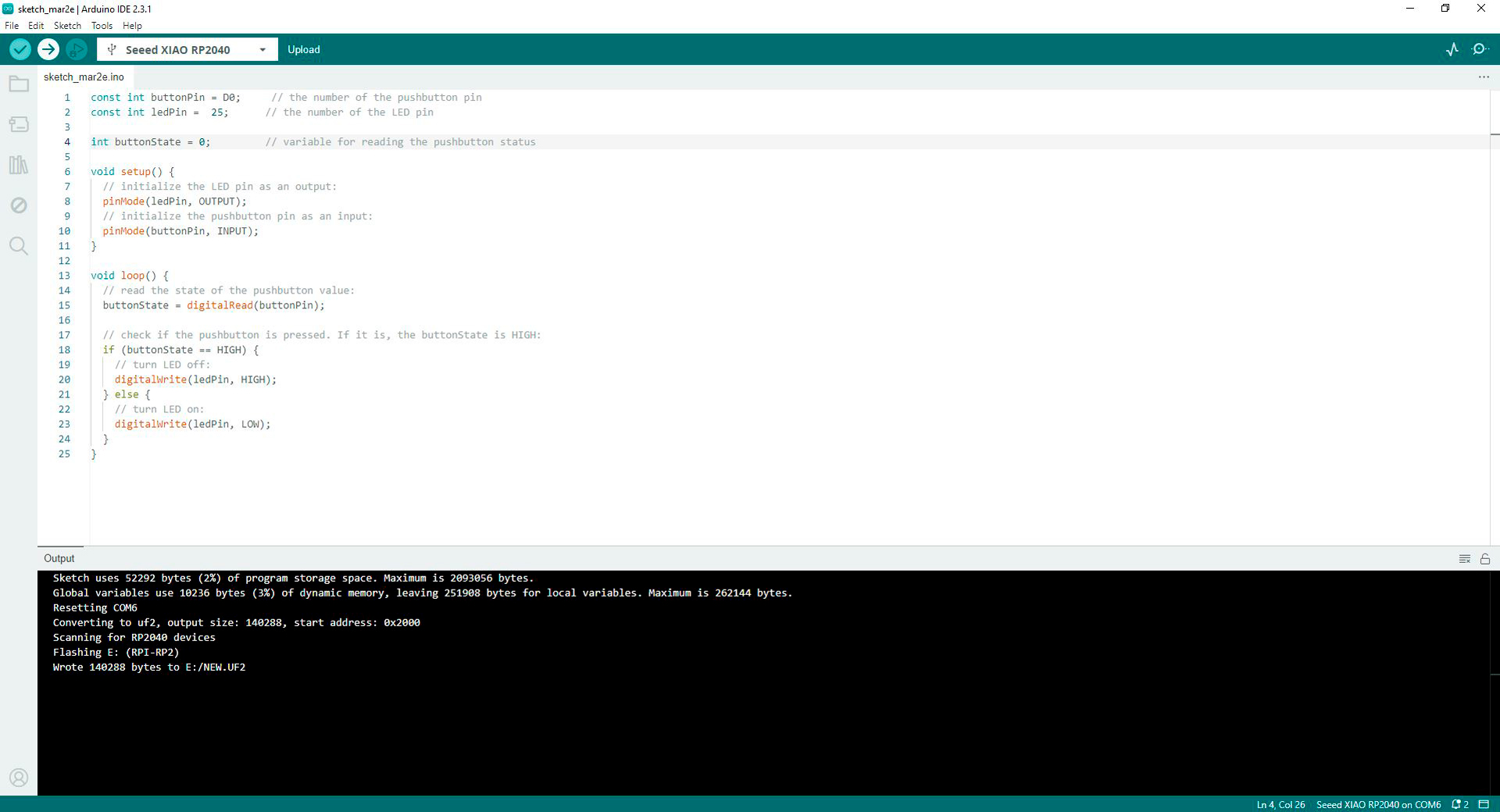
Based on the code obtained in the guide, I managed to program the following action: every time I pressed the button, the LED on the XIAO RP2040 would turn on. I used this code in Arduino IDE:
const int buttonPin = D0;  //The number of the pushbutton pin
const int ledPin = 25;     //The number of the LED pin

int buttonState = 0;       //Variable for reading the pushbutton status

void setup()  {
  //Initialize the LED pin as an output
  pinMode(ledPin, OUTPUT);
  //Initialize the pushbutton pin as an input
  pinMode(buttonPin, INPUT);
}

void setup()  {
  //Read the state of the pushbutton value
  buttonState = digitalRead(buttonPin);

  //Check if the pushbutton is pressed. If it is, the buttonState is HIGH
  if (buttonState == HIGH)  {
    //Turn LED off
	digitalWrite(ledPin, HIGH);
  }	else {
    //Turn LED on
	digitalWrite(ledPin, LOW);
  }
}
Code in Arduino IDE for programming blue LED on XIAO RP2040 (pin 25) blinks every time the button is pressed
Blue LED on XIAO (pin 25) blinks every time the button is pressed
To activate the LED on the breadboard with the button, I modify line 2 with pin number 27. I used this code in Arduino IDE:
const int buttonPin = D0;  //The number of the pushbutton pin
const int ledPin = 27;     //The number of the LED pin

int buttonState = 0;       //Variable for reading the pushbutton status

void setup()  {
  //Initialize the LED pin as an output
  pinMode(ledPin, OUTPUT);
  //Initialize the pushbutton pin as an input
  pinMode(buttonPin, INPUT);
}

void setup()  {
  //Read the state of the pushbutton value
  buttonState = digitalRead(buttonPin);

  //Check if the pushbutton is pressed. If it is, the buttonState is HIGH
  if (buttonState == HIGH)  {
	//Turn LED off
	digitalWrite(ledPin, HIGH);
  }	else {
	//Turn LED on
	digitalWrite(ledPin, LOW);
  }
}
Code in Arduino IDE for programming LED on brearboard turns off every time the button is pressed
LED on brearboard connected to pin 27 turns off every time the button is pressed
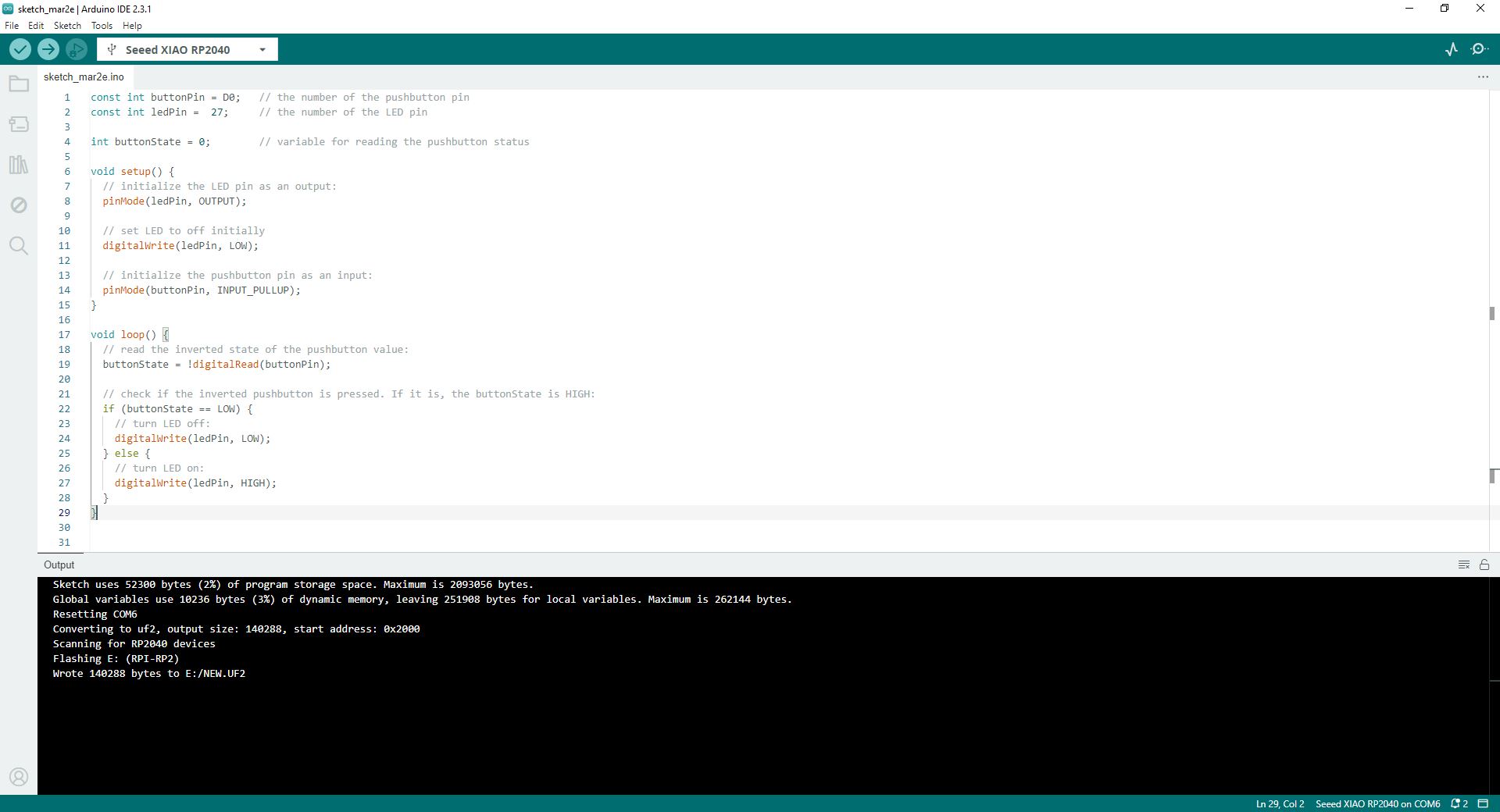
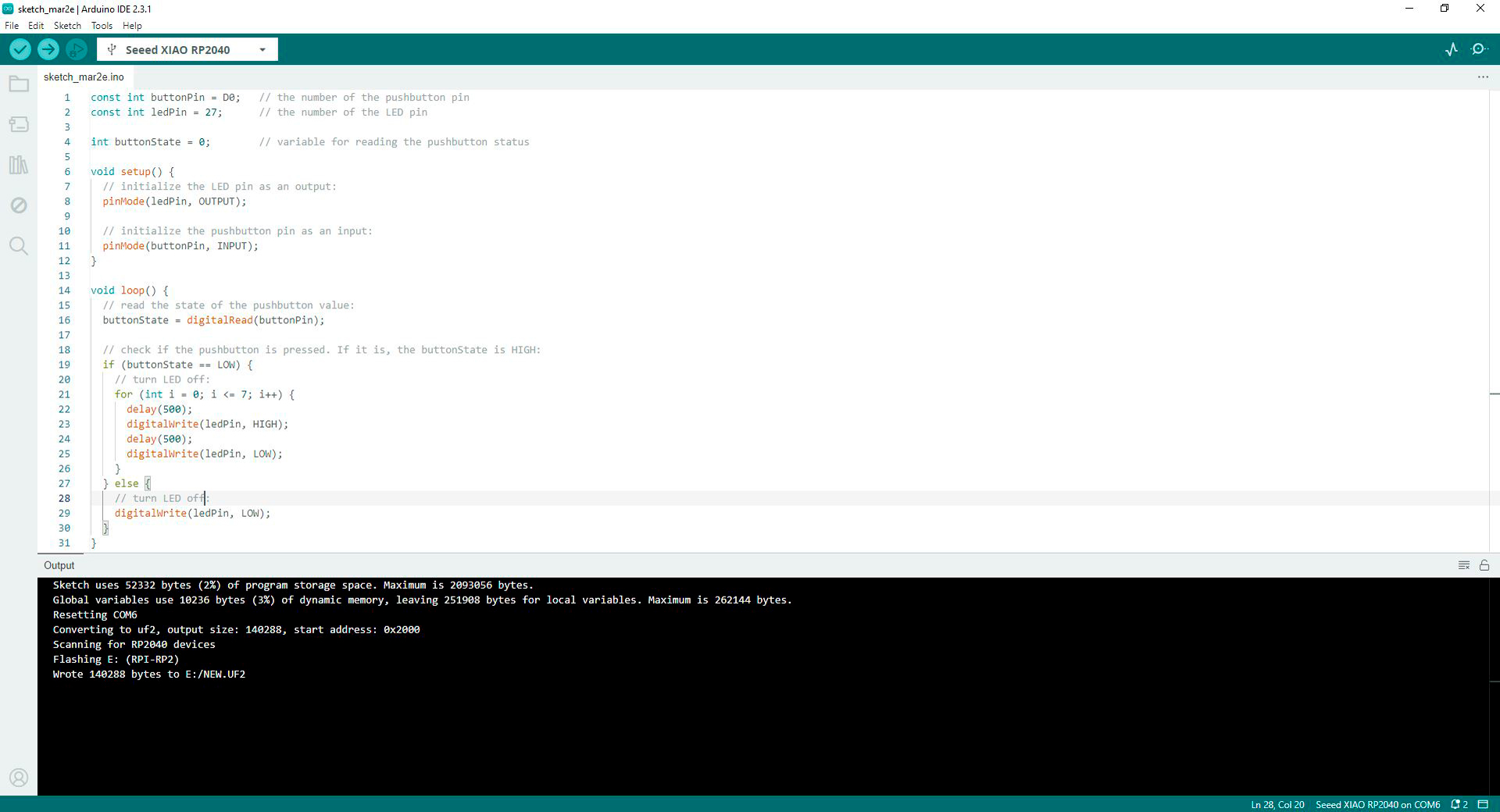
What I was looking for with the previous code was for the LED to be off and turn on when the button was pressed, so I modified the code. It worked. I used this code in Arduino IDE:
const int buttonPin = D0;  //The number of the pushbutton pin
const int ledPin = 27;     //The number of the LED pin

int buttonState = 0;       //Variable for reading the pushbutton status

void setup()  {
  //Initialize the LED pin as an output
  pinMode(ledPin, OUTPUT);

  //Set LED to off initially
  digitalWrite(ledPin, LOW);

  //Initialize the pushbutton pin as an input
  pinMode(buttonPin, INPUT_PULLUP);
}

void setup()  {
  //Read the inverted state of the pushbutton value
  buttonState = !digitalRead(buttonPin);

  //Check if the inverted pushbutton is pressed. If it is, the buttonState is HIGH
  if (buttonState == LOW)  {
	//Turn LED off
	digitalWrite(ledPin, LOW);
  }	else {
	//Turn LED on
	digitalWrite(ledPin, HIGH);
  }
}
Code in Arduino IDE for programming LED on brearboard turns on every time the button is pressed
LED on brearboard connected to pin 27 turns on every time the button is pressed
What a thrill! I started programming some basic actions. So, I wanted to add some more complexity. When button is pressed, the LED should turn on and off 8 times. To generate this new code, I relied on my colleague Ronal Vilca. After modifying the initial code, I used this code in Arduino IDE:
const int buttonPin = D0;  //The number of the pushbutton pin
const int ledPin = 27;     //The number of the LED pin

int buttonState = 0;       //Variable for reading the pushbutton status

void setup()  {
  //Initialize the LED pin as an output
  pinMode(ledPin, OUTPUT);

  //Initialize the pushbutton pin as an input
  pinMode(buttonPin, INPUT);
}

void loop()  {
  //Read the state of the pushbutton value
  buttonState = digitalRead(buttonPin);

  //Check if the pushbutton is pressed. If it is, the buttonState is HIGH
  if (buttonState == LOW)  {
	//Turn LED off
	for (int i = 0; i <= 7; i++)  {
	  delay(500);
	  digitalWrite(ledPin, HIGH);
	  delay(500);
	  digitalWrite(ledPin, LOW);
	}
  } else {
	//Turn LED off
	digitalWrite(ledPin, LOW);
  }
}
Code in Arduino IDE for programming LED to blink 8 times after the button is pressed
Code of LED that blinks 8 times after the button is pressed well programmed
Based on the previous code, I programmed the XIAO RP2040 so that every time the button was pressed, it would send a signal back to the Arduino serial monitor. I used this code in Arduino IDE:
const int buttonPin = D0;  //The number of the pushbutton pin
const int ledPin = 27;     //The number of the LED pin

int buttonState = 0;       //Variable for reading the pushbutton status

void setup()  {
  Serial.begin(9600);

  //Initialize the LED pin as an output
  pinMode(ledPin, OUTPUT);

  //Initialize the pushbutton pin as an input
  pinMode(buttonPin, INPUT);
}

void loop()  {
  //Read the state of the pushbutton value
  buttonState = digitalRead(buttonPin);

  //Check if the pushbutton is pressed. If it is, the buttonState is HIGH
  if (buttonState == LOW)  {
	//Turn LED off
	Serial.printIn("Button Pressed")
	for (int i = 0; i <= 7; i++)  {
      delay(500);
      digitalWrite(ledPin, HIGH);
      delay(500);
      digitalWrite(ledPin, LOW);
    }
  } else {
 	//Turn LED off
 	digitalWrite(ledPin, LOW);
   }
 }
Code in Arduino IDE for programming LED on brearboard connected XIAO RP2040 (pin 27) turns on every time the button is pressed
Proccess of programming LED on brearboard connected XIAO RP2040 (pin 27) turns on every time the button is pressed
After this initial exploration, I felt ready to program on my Quentorres.
Programming XIAO RP2040 in Quentorres
For accomplish this code, my colleague Ronal Vilca helped me with the code. I used this code in Arduino IDE:
const int ledPin = D6;     // the number of the LED pin
const int buttonPin = D1;  // the number of the pushbutton pin
int buttonState = 0;       // variable for reading the pushbutton status

void setup()
{
  Serial.begin(9600);
  pinMode(buttonPin, INPUT);
  pinMode(ledPin, OUTPUT);

}
void loop()
{
  buttonState = digitalRead(buttonPin);
  if (buttonState == HIGH) {
  for (int i=0; i<=7; i++)
  {
    delay(500);
    digitalWrite(ledPin, HIGH);
    delay(1000);
    digitalWrite(ledPin, LOW);

  }
} else {

  digitalWrite(ledPin, LOW);
}

}
Code in Arduino IDE for programming the LED to blink 8 times and send data to the serial monitor
Code of LED that blinks 8 times and send data to the serial monitor well programmed
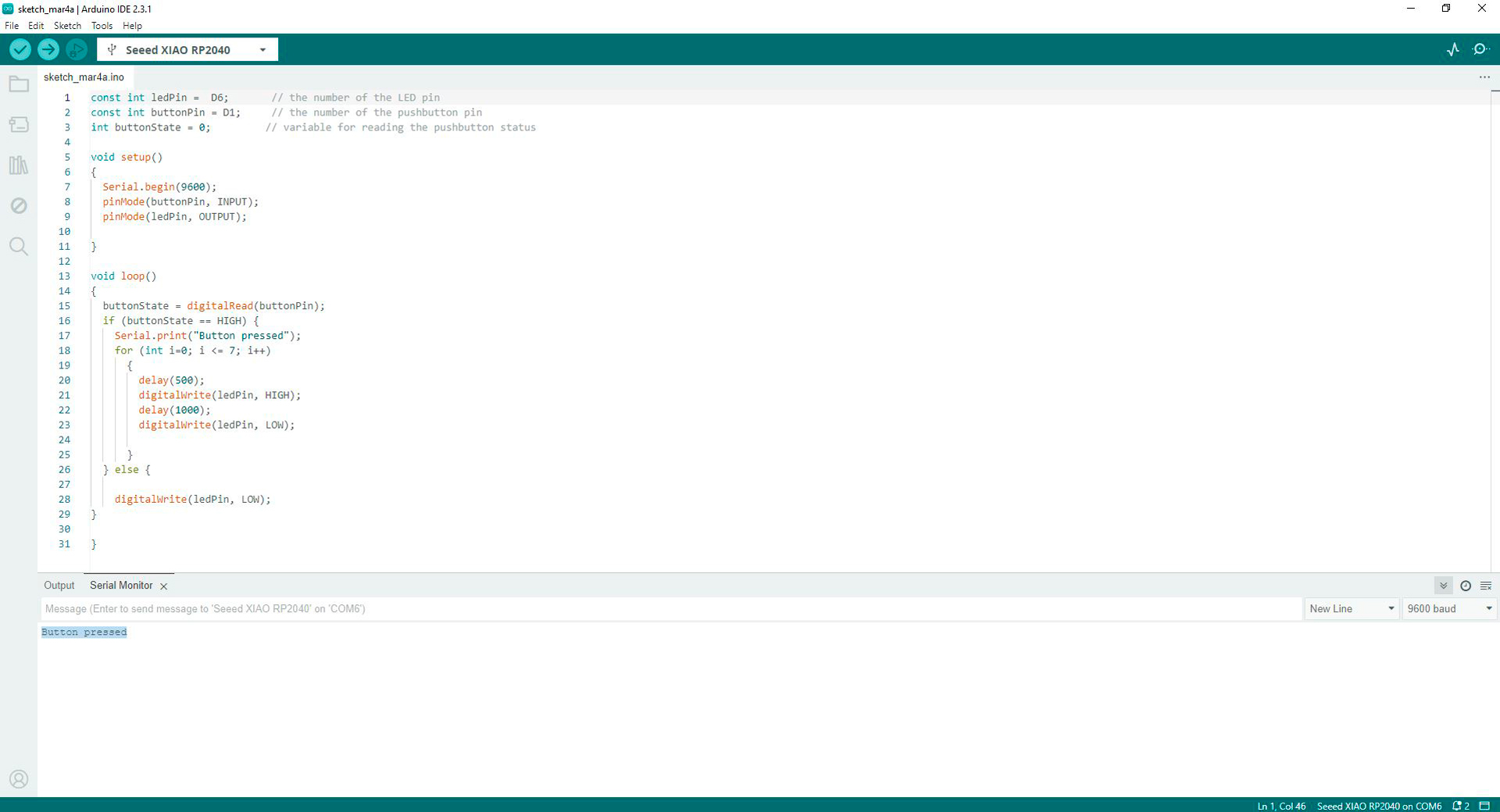
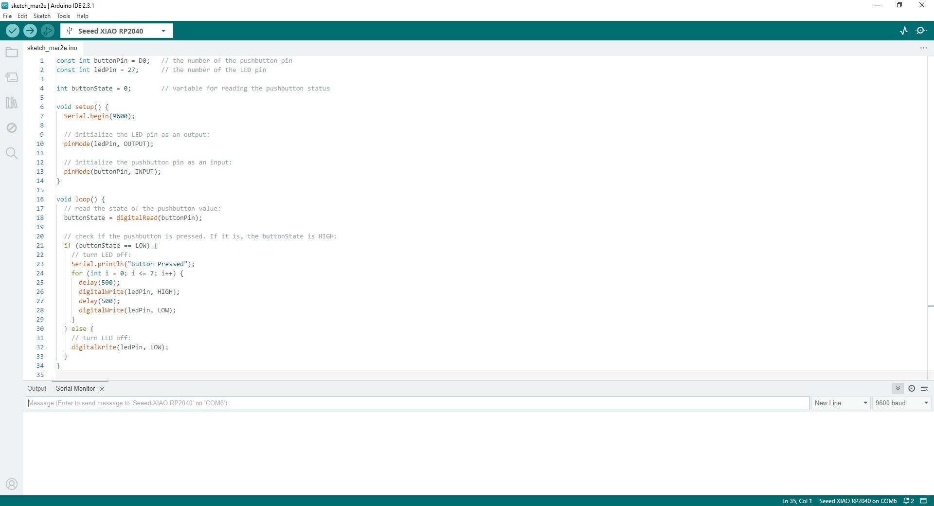
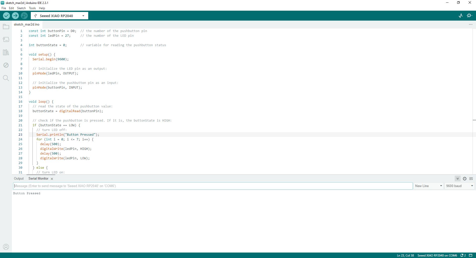
The code worked. Every time I pressed the button in Quentorres, the message "button pressed" was shown in the serial monitor in Arduino IDE and the LED turned on 8 times.
Message in serial monitor in Arduino IDE
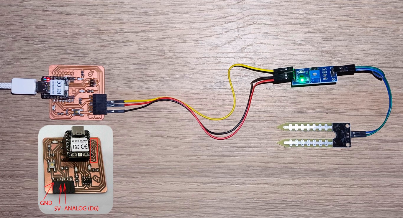
I felt very happy and motivated when the code worked. So I decided to program a soil moisture sensor. I followed this guide for connecting the wires and my colleague Ronal Vilca draw a really helpful scheme.
Hygrometer connected to Quentorres
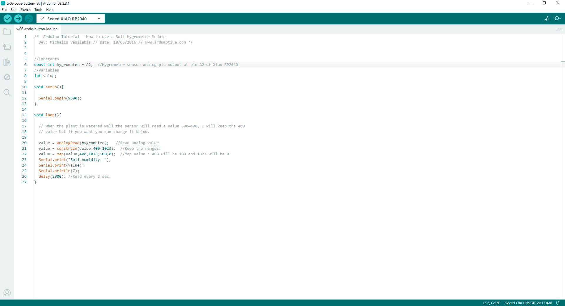
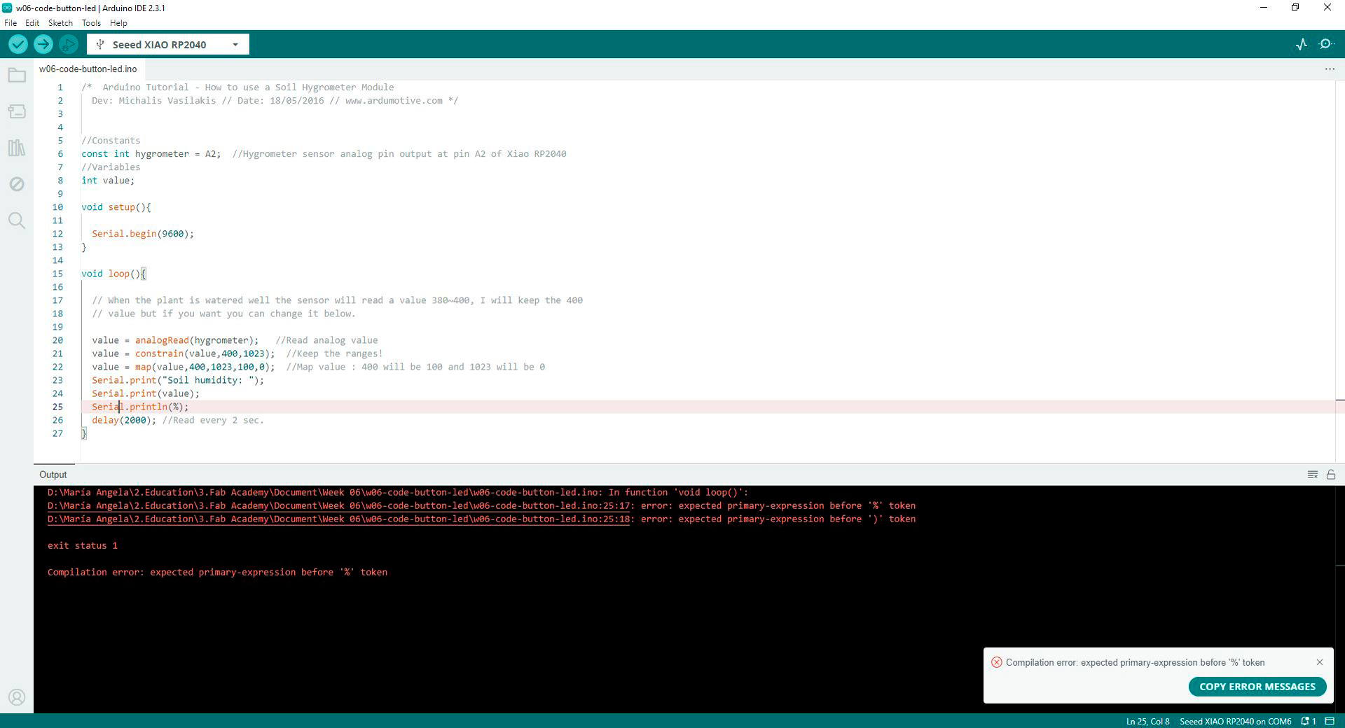
I found this code and changed pin A0 (in the code) for A2 (in my case). I verified the code and I got an error in the simbol %. I changed for "%" and it worked.
// constants
const int hygrometer = A2;  // hygrometer sensor analog pin output at pin A2 of XIAO RP2040
// variables
int value;

void setup(){

  Serial.begin(9600);
}

  void loop(){
  // when the plant is watered well the sensor will read a value 380∼400, I will keep the 400
  // value but if you want you can change it below.

  value = analogRead(hygrometer);     // read analog value
  value = constrain(value,400,1023);  // keep the ranges
  value = map(value,400,1023,100,0);  // map value: 400 will be 100 and 1023 will be 0
  Serial.print("Soil humidity: ");
  Serial.print(value);
  Serial.println("%");
  delay(10000);                       // read every 10 seconds
}
Code in Arduino IDE for programming soil moisture sensor to detect percentage of humidity and display it on serial monitor in Arduino IDE
Proccess of programming soil moisture sensor that detects percentage of humidity and displayed it on serial monitor in Arduino IDE
I am happy with the result about the hygrometer. With it I also started understanding better my final project programming and electronics.
Conclusions
If you are afraid of burning your microprocessor or any component, start on a breadboard. I gained confidence after achieving some basic programming.
When programming, you start by modifying codes that already work. Arduino IDE has an extensive library that contains many basic actions to learn.
Then, change some numbers and texts. Add or remove lines and check if the code is correct. If so, charge it and see what it does.
Use ChatGPT to modify codes is you are a begginer as I was. Keep in mind that you must be clear when writing the prompt. In my case I used ChatGPT especially to correct some actions. I used this promt: I want to (output) in (microcontroller name) to do (action) in this code (paste the code you want to modify).
Complex Instruction Set Computers (CISC) embody intricacy and versatility, accommodating a broad range of instructions capable of executing multiple operations within a single command. Meanwhile, Reduced Instruction Set Computers (RISC) epitomize simplicity and efficiency, focusing on streamlined instruction sets that execute individual operations swiftly and autonomously. These contrasting design philosophies cater to diverse computing needs, with CISC architectures suited for intricate tasks requiring multifaceted operations, and RISC architectures excelling in environments where speed and resource optimization are paramount.
To finish this task I thank my fellow students and tutors, especially Ronal Vilca, Silvana Espinoza, and Jesus Lucero for helping me understand the code and solder my Quentorres.