Table of Contents
BIG why?
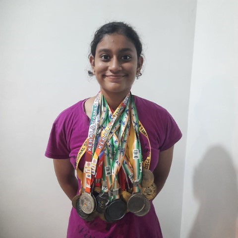
I am a proud sister of a National-level swimmer, Tasha. She started swimming classes when she was four years old. I still remember how she used to say she was terrified of the big pool since she started her practice in the baby pool.
At that time, I was part of the aquatic team at my school and had coaching after school hours. Since we were coming back together from school, Tasha also started coaching in the big pool and she loved it. Since then, her dream has been to win the Olympics.
She has coaching every day in the morning from 5:00 AM to 8:00 AM, and after school till 3:00 PM, she has her evening coaching from 3:30 to 6:30 PM. She has a pretty hectic schedule. However, the problem with intense coaching is that it's necessary to maintain muscle strength and a protein-rich diet.
Although my sister remained the champion consecutively for five years, she had to succumb to a shoulder injury. She stopped swimming for a year, saying goodbye to her Olympic dream.
But you could see how much she wished to conquer the waters, and after treatment, she rejoined swimming.
With the one-year gap, she wasn't the champion anymore. Her competitors were far ahead of her. All her gold medals had turned to silver and bronze. Even with intense training and additional muscle strengthening, it was difficult for her to come back to her best time.
Since I was studying electronics engineering, she asked me to build something in which there was an indication for her to know when she was going slow so she could swim faster accordingly. Normally, during time trials, the coach uses a stopwatch to measure her best time. There was no indication as to what point in time she was going slow or when her target time had passed.
So when I had to choose a project for Fab Academy, I thought, why not give it a shot? It's the least I could do to support my little sister's dream.
The Idea and features
The idea is to design a watch that will:
1. Allow users to set target time via a dedicated app.
2. Provide real-time data updates on speed, time, and lap counts during swimming.
3. Monitor and track speed and time, counting the number of laps completed.
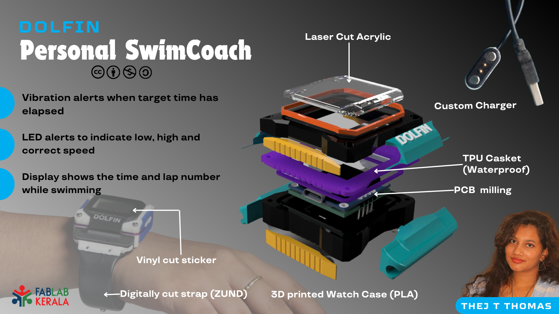
4. Send vibration alerts if the swimmer’s time has elapsed.
5. Use RGB LEDs to change colors based on the swimmer’s performance, providing visual feedback.
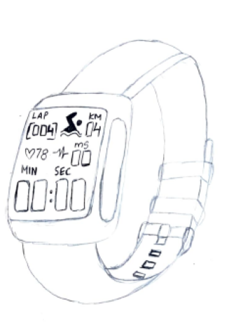
Rough Sketch
The display should show time in minutes, seconds and milliseconds, lap number, time and if possible I have plans to measure the heartrate and BP.
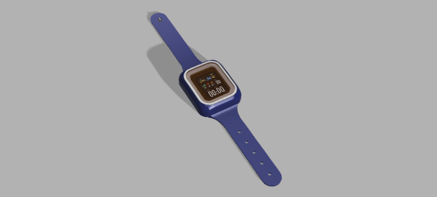
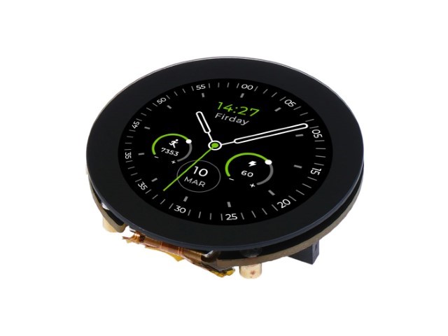
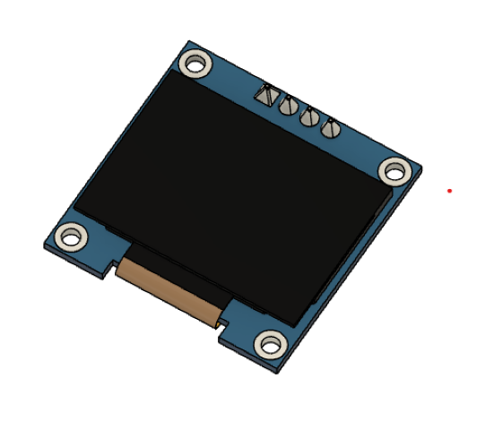
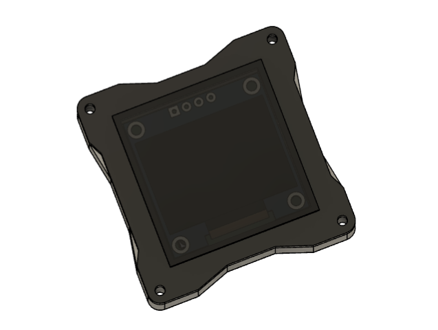
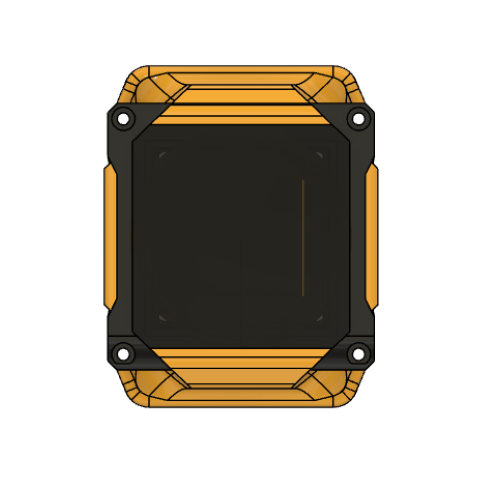
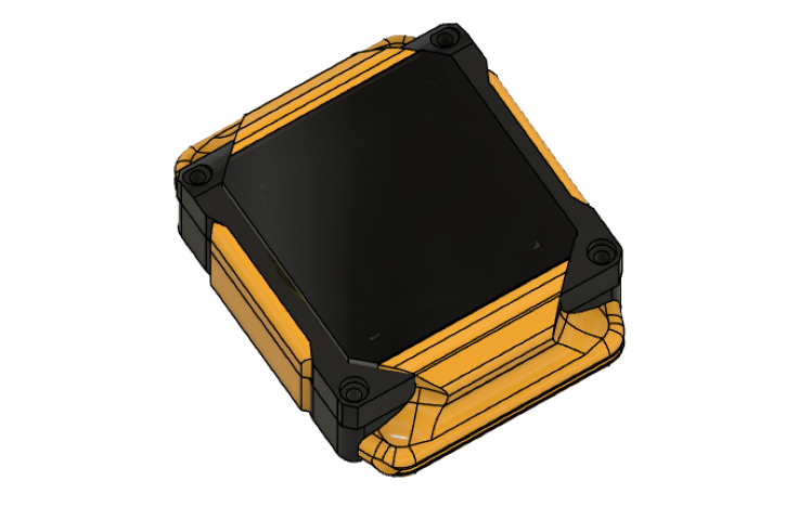
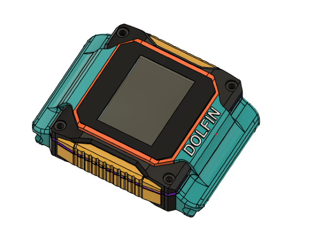
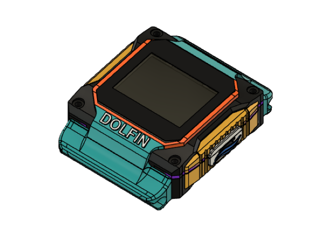
CAD
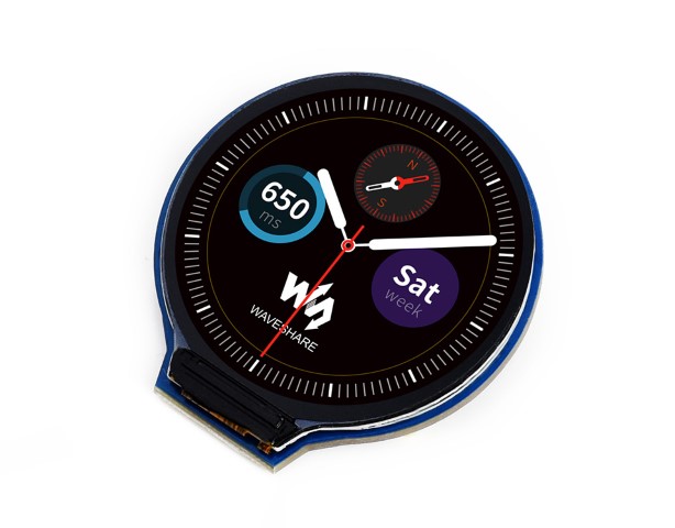
I had designed the watch using Waveshare 1.69inch LCD Display
Project Plan
The "DOLFIN" smartwatch project aims to count strokes, laps, speed, and time. Completed tasks include programming for strokes and laps, TinyML implementation, component procurement, and PCB design. Remaining tasks are 3D printing, PCB milling, waterproofing, final programming, Bluetooth communication, strap making, and charger making. Challenges include improving stroke counting accuracy, waterproofing solutions, USB port replacement, BLE connection, and battery life optimization. Customizations involve using an OLED display, coin vibration motor, and developing alternative control methods. Unresolved issues include waterproofing, button and USB port removal, BLE functionality, deep sleep mode, and app development. More details in project development, application & implication and system integration
PHASE I
Electronics
Choosing the microcontroller
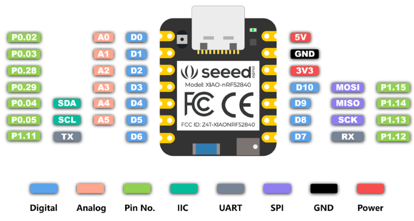
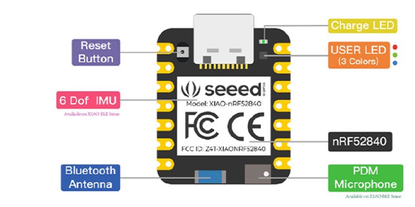
Seeed Studio XIAO nRF52840 Sense was the correct choice for my project because of its small and exquisite form-factor, 6-axis Inertial Measurement Unit (IMU), Bluetooth 5.0 with onboard antenna, Battery charging chip and Ultra-Low Power. More details available in week 11. More details about the board and how to set it up is available in this documentation.
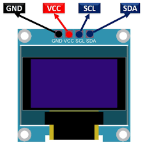
The display dilemma
Out of innumerable displays available I had to choose the display that could minimise packaging size. I experimented with few displays such as the 1.28" Round LCD Display Module and Seeed Studio 1.28-inch Round Touch Display for XIAO
However upon experimentation, I discovered that there was not library supporting xiao for first display and even though xiao supports the second display the display and IMU couldn't work simultaneously.
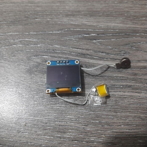
More details here in week nine.One important factor is note while choosing the display is the power source. Since I had to use the smallest battery possible due to size constraints, the one I found was the battery used in airpods of 3.7V. So I had to choose a display supporting 3.3V since the pinout from the microcontroller had 3.3V and also compatible with the microcontroller. Satisfying all these constraints was the OLED display. Although its not colour display, it serves the purpose.
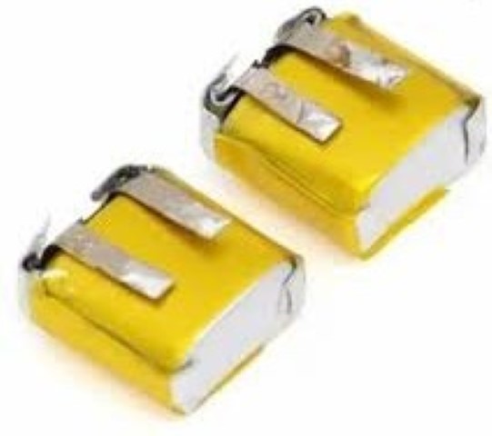
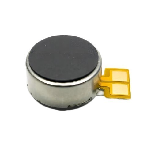
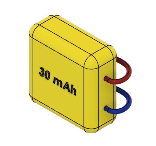
Battery & Motor
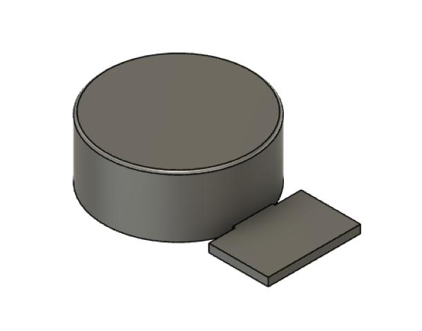
As I mentioned before I battery I chose is 35 mAh 3.7V single cell Rechargeable LiPo Battery and its dimensions are 12 x 10 x 4.5mm making it conveinent for my mini packaging. And I chose this micro coin vibration motor with rated Voltage (Vac RMS) of 2.5v and dimemsions of 9mm diameter and 4 mm thickness.
Choosing the LED
My plan was to use NeoPixel WS812B mini. But upon reviewing its datasheet I found out I couldn't use it due to its voltage requirements. Microcontroller could only supply 3.3V and even though I could power it from the battery I didn't want to compromise the battery usage and efficiency.
.png)
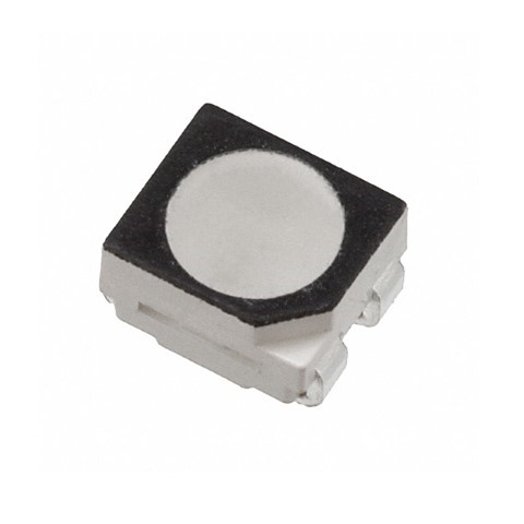
I still needed an RGB LED because I want different colours to indicate speed. So I thought of using LED RGB CLEAR 4PLCC SMD which has voltage rating of 3V.
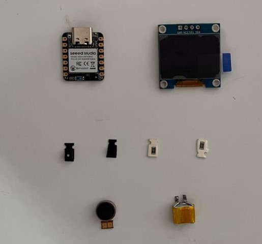
Procurement
Since all electronic components has been decided, next step is to procure them. Additionally I needed resistors and mosfet to drive the motor. Almost all components were available at the lab except for motor and the battery.
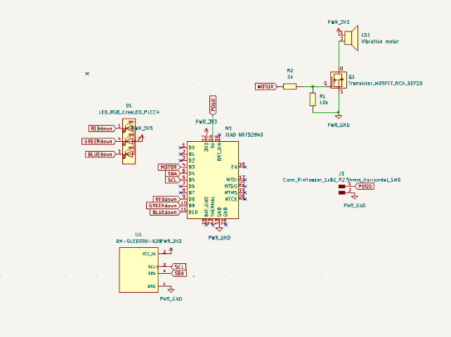
PCB Design
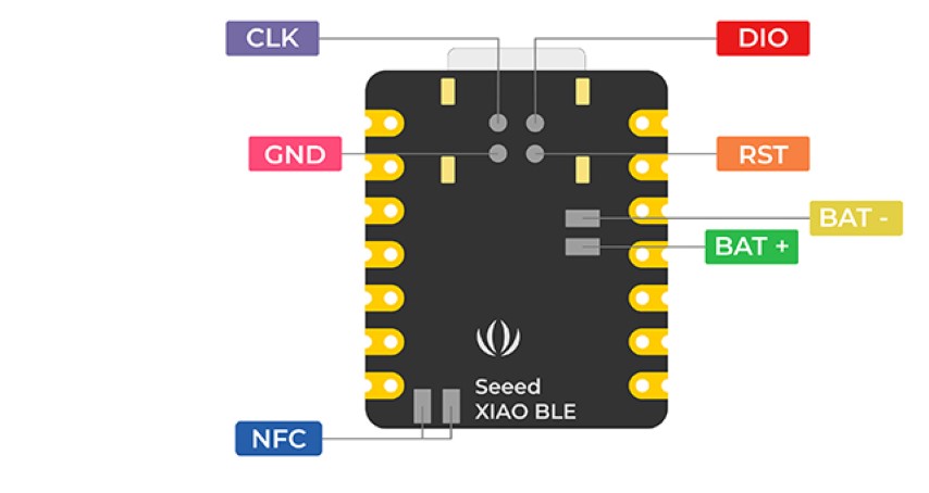
Here is the schematic in KiCad. The label 'POGO' refers to the pin that will be used for charging via POGO discs and POGO pin. The microcontroller supports battery charging via the USB cable but however due to problem of waterproofing I had to find an alternative to minimise water entry-points. While refering the schematic of the microcontroller it was found that the 5V and GND pin could be used for charging.
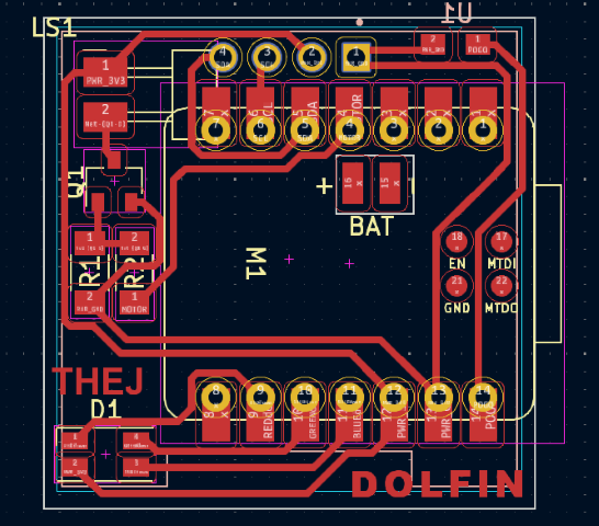
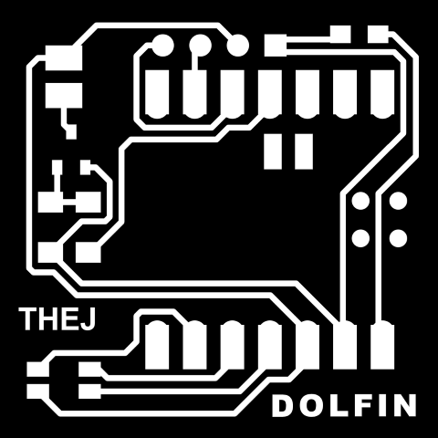
The PCB design. So it is at this point of time I had changed the name of the watch from Aqua Sense to DOLFIN. It was simply to accommodate the name to the PCB. I also added my name. Even though it will be milled only single side, this is a PCB with double sided component. The OLED display will be soldered on the back side. Additionaly a cut will be made in the PCB to wire the connections of BAT+ and BAT- of the microcontroller to the battery. I would like to use PWM to use the motor to vibrate in different modes so I've incorporated the mosfet and resistors to drive the motor.
.png)
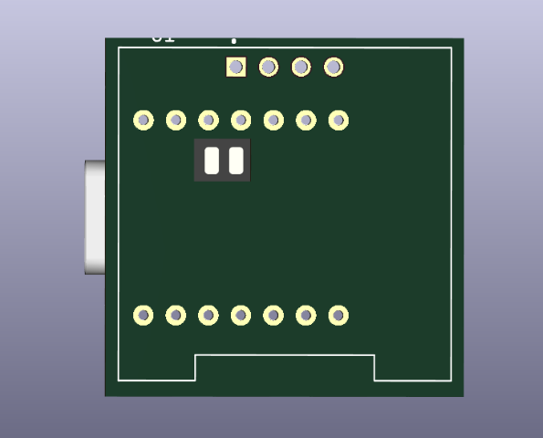
Next step is to export the Gerber file and convert it into PNG for milling. Our FabLab has a special website for this conversion. Visit this website. After uploading the gerber file, using the options, chose top layer, top cut and drill to generate the png files.


Milling & Soldering
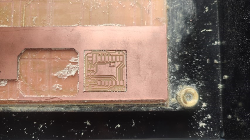
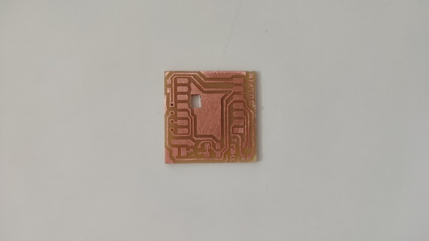
Using Roland Modela MDX20, I uploaded the PNG files using FabMods and milled the PCB. It took 8 minutes
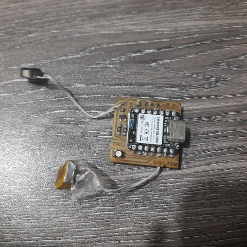
Next I soldered all the components. My instructor helped to solder the OLED display onto the backside by using the header pin and then cutting the pin height to minimise the distance between the board and the display. Additionally insulated wires were soldered into battery pins and the pins for the motor. I used tape aroung the battery wires to avoid them getting short.
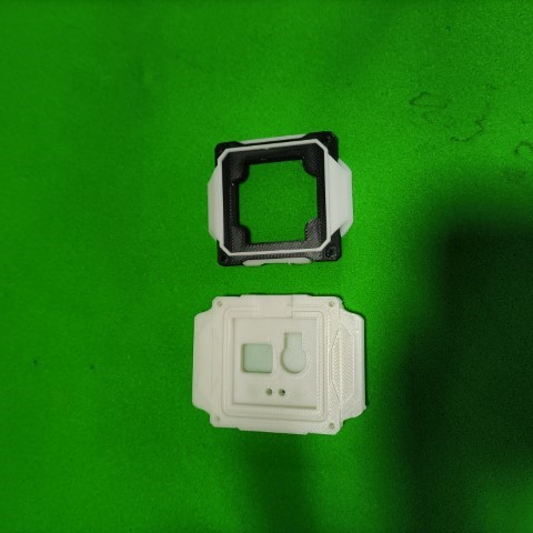
CAD
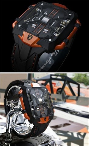
As I was browsing for design ideas, I had noticed that all smart watches followed a minimalist design of a watch case. Creativity was found only at the straps of all smart watches. Even though the watch I had designed in week two was the same like all watches, I followed that design since it was a swimminng watch and it needed a sleek design. However I wanted to experiment with maximalist design on a smart watch. Here's my inspiration.
First I exported the 3D models of the electronic components which were not on my PCB i.e. the battery, motor and OLED. I wasn't able to get the correct file of motor so I designed one myself. For the OLED, there were multiple files available so I measured and found the closest one to the one I had. Also with the battery were few mm difference.
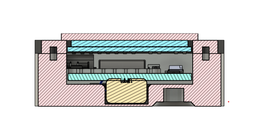
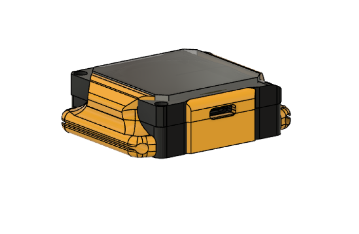
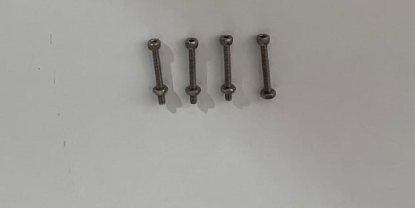
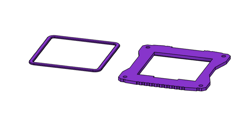
So the plan to keep packaging as small as possible. There will be a gasket in between the top and bottom part for waterproofing. 2mm screws will be used for tightening the two parts. This is the system integration with all electronic components.
So for waterproofing, the plan is to print a gasket between the two parts in flexible resin in Formlabs. This is the design:
My FAB mate Baasil had an extra apple watch strap I could use. So to fit that strap I downloaded its STL file. Upon printing it, I realised it wouldn't fit the strap so, I gave a 0.2mm tolerance. When I tested it with the strap it fitted perfectly.
Next thing was the charger. To minimise water entry points, it was decided to use the pogo pin and disc charging. So here's the design of the charger, it is a snap-fit box and the hole on the side is for the wire.
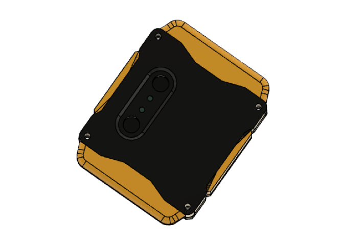
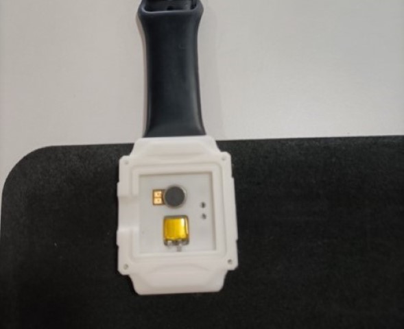
Next was to focus on the overall look of the watch. My instructor Mufeed helped as designing wasn't my strong suit. This was the first look of the watch.
The backside has space for the pogo pin charger. And the hole provided in the side was provisioned for now so I could do ML training of strokes movements while was siter was wearing the watch.
3D printing
Since the design was ready, the next part was printing to test the design and its measurements. As I mentioned before, this is a 2 part design, so the STL of two bodies were exported and sliced in Bambu studio. 2 colours were added for the top part- black and white.
Printing started in Bambu Lab X1 Carbon. It took about 5 hours.
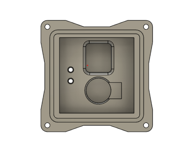
Here is the result. It was tested with the apple watch strap and it fit well.
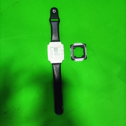
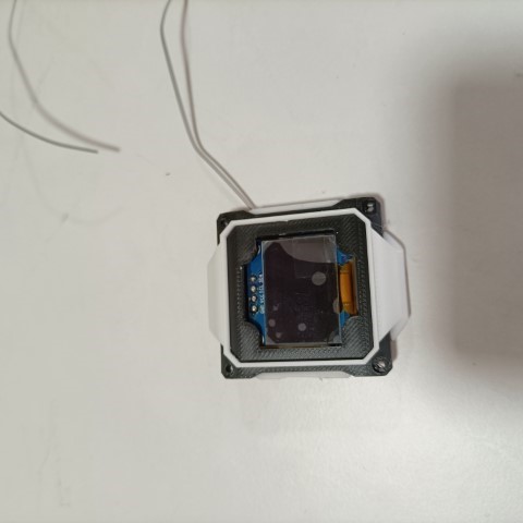
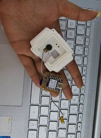
The PCB also fit well into the part, the display was also positioned correctly.
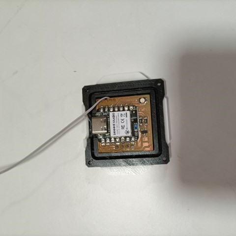
The motor was designed to be pressfit into the compartment since it was a vibration motor. However battery had to be a little bit loose since it had to hold the wire also. That turned out to be good as well.
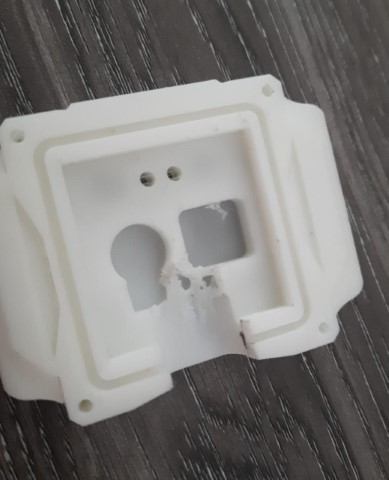
Problem
As I was happy that all parts were fitting well. There seemed to be a problem. These 2 parts weren't closing. It turns out space wasn't enough for the USB. So I had shave off the bottom region to fit the parts. Yes, I could take another print but there wasn't enough time for that day. This part was designed with hole on the side so I could train my sister's stroke movements and only that day my sister was available for training her strokes.
Programming Phase 1
Since the part with hole provisioned for programming was ready, I thought I'll begin with some basic programming. I had already tested the program to count the number of strokes with just the microcontroller tied around my sister's wrist. This is actually a modified pedometer algorithm found in the examples of XIAO NRF52840 Sense.
  #include "LSM6DS3.h"
  #include "Wire.h"

  #define CLEAR_STEP      true
  #define NOT_CLEAR_STEP  false

  //Create a instance of class LSM6DS3
  LSM6DS3 pedometer(I2C_MODE, 0x6A);    //I2C device address 0x6A

  void setup()
  {
    Serial.begin(9600);
    while (!Serial);
    if (pedometer.begin() != 0)
    {
      Serial.println("Device error");
    } else
    {
      Serial.println("Device OK!");
    }

    //Configure LSM6DS3 as pedometer
    if (0 != config_pedometer(NOT_CLEAR_STEP))
    {
      Serial.println("Configure strokemeter fail!");
    }
    Serial.println("Success to Configure strokemeter!");
  }

  void loop()
  {
    uint8_t dataByte = 0;
    uint16_t stepCount = 0;

    pedometer.readRegister(&dataByte, LSM6DS3_ACC_GYRO_STEP_COUNTER_H);
    stepCount = (dataByte << 8) & 0xFFFF;

    pedometer.readRegister(&dataByte, LSM6DS3_ACC_GYRO_STEP_COUNTER_L);
    stepCount |=  dataByte;

    Serial.print("Number of strokes: ");
    Serial.println(stepCount);

    delay(500);
  }

  //Setup pedometer mode
  int config_pedometer(bool clearStep)
  {
    uint8_t errorAccumulator = 0;
    uint8_t dataToWrite = 0;  //Temporary variable

    //Setup the accelerometer******************************
    dataToWrite = 0;

    //  dataToWrite |= LSM6DS3_ACC_GYRO_BW_XL_200Hz;
    dataToWrite |= LSM6DS3_ACC_GYRO_FS_XL_2g;
    dataToWrite |= LSM6DS3_ACC_GYRO_ODR_XL_26Hz;


    // Step 1: Configure ODR-26Hz and FS-2g
    errorAccumulator += pedometer.writeRegister(LSM6DS3_ACC_GYRO_CTRL1_XL, dataToWrite);

    // Step 2: Set bit Zen_G, Yen_G, Xen_G, FUNC_EN, PEDO_RST_STEP(1 or 0)
    if (clearStep)
    {
      errorAccumulator += pedometer.writeRegister(LSM6DS3_ACC_GYRO_CTRL10_C, 0x3E);
    } else
    {
      errorAccumulator += pedometer.writeRegister(LSM6DS3_ACC_GYRO_CTRL10_C, 0x3C);
    }

    // Step 3:  Enable pedometer algorithm
    errorAccumulator += pedometer.writeRegister(LSM6DS3_ACC_GYRO_TAP_CFG1, 0x40);

    //Step 4: Step Detector interrupt driven to INT1 pin, set bit INT1_FIFO_OVR
    errorAccumulator += pedometer.writeRegister(LSM6DS3_ACC_GYRO_INT1_CTRL, 0x10);

    return errorAccumulator;
  }
Now my aim was to calculate the number of laps and the distance covered. So for that, I mapped each stroke to 140 cms, this refers to the length covered by both arms of my sister during freestyle stroke. For distance, the pool length is set to 25 metres. So while the strokes will be counted, number of laps based on the distance will be calculated.
  #include "LSM6DS3.h"
  #include "Wire.h"

  #define CLEAR_STEP      true
  #define NOT_CLEAR_STEP  false

  // Create an instance of the LSM6DS3 class
  LSM6DS3 pedometer(I2C_MODE, 0x6A);    // I2C device address 0x6A

  #define STROKE_LENGTH_CM 140  // Length of one stroke in centimeters

  // Variables to keep track of distance and laps
  uint16_t stepCount = 0;
  float totalDistance = 0.0;
  int lapCount = 0;
  float poolLength = 0.0;

  void setup()
  {
    Serial.begin(9600);
    while (!Serial);

    if (pedometer.begin() != 0)
    {
      Serial.println("Device error");
    } else
    {
      Serial.println("Device OK!");
    }

    // Configure LSM6DS3 as pedometer
    if (0 != config_pedometer(NOT_CLEAR_STEP))
    {
      Serial.println("Configure pedometer fail!");
    } else
    {
      Serial.println("Success to configure pedometer!");
    }

    // Input the length of the pool
    Serial.println("Enter the length of the pool (in meters):");
    while (Serial.available() == 0) {} // Wait for user input
    poolLength = Serial.parseFloat();
    Serial.print("Pool length set to: ");
    Serial.print(poolLength);
    Serial.println(" meters");
    Serial.println();
  }

  void loop()
  {
    uint8_t dataByte = 0;
    uint16_t newStepCount = 0;

    // Read the step counter high byte
    pedometer.readRegister(&dataByte, LSM6DS3_ACC_GYRO_STEP_COUNTER_H);
    newStepCount = (dataByte << 8) & 0xFFFF;

    // Read the step counter low byte
    pedometer.readRegister(&dataByte, LSM6DS3_ACC_GYRO_STEP_COUNTER_L);
    newStepCount |= dataByte;

    // Calculate the number of new steps since the last read
    uint16_t stepsTaken = newStepCount - stepCount;
    stepCount = newStepCount;

    // Update total distance covered (convert cm to meters)
    totalDistance += (stepsTaken * STROKE_LENGTH_CM) / 100.0;

    // Check if a lap is completed
    if (totalDistance >= poolLength) {
      lapCount++;
      totalDistance -= poolLength;  // Subtract the pool length to get the remaining distance

      Serial.print("Lap completed! Total laps: ");
      Serial.println(lapCount);
    }

    // Print the number of strokes and the total distance covered
    Serial.print("Number of strokes: ");
    Serial.print(stepCount);
    Serial.print("\tTotal Distance: ");
    Serial.print(totalDistance, 2);
    Serial.println(" meters");

    delay(500);
  }

  // Setup pedometer mode
  int config_pedometer(bool clearStep)
  {
    uint8_t errorAccumulator = 0;
    uint8_t dataToWrite = 0;  // Temporary variable

    // Setup the accelerometer
    dataToWrite = 0;

    dataToWrite |= LSM6DS3_ACC_GYRO_FS_XL_2g;
    dataToWrite |= LSM6DS3_ACC_GYRO_ODR_XL_26Hz;

    // Step 1: Configure ODR-26Hz and FS-2g
    errorAccumulator += pedometer.writeRegister(LSM6DS3_ACC_GYRO_CTRL1_XL, dataToWrite);

    // Step 2: Set bit Zen_G, Yen_G, Xen_G, FUNC_EN, PEDO_RST_STEP(1 or 0)
    if (clearStep)
    {
      errorAccumulator += pedometer.writeRegister(LSM6DS3_ACC_GYRO_CTRL10_C, 0x3E);
    } else
    {
      errorAccumulator += pedometer.writeRegister(LSM6DS3_ACC_GYRO_CTRL10_C, 0x3C);
    }

    // Step 3: Enable pedometer algorithm
    errorAccumulator += pedometer.writeRegister(LSM6DS3_ACC_GYRO_TAP_CFG1, 0x40);

    // Step 4: Step Detector interrupt driven to INT1 pin, set bit INT1_FIFO_OVR
    errorAccumulator += pedometer.writeRegister(LSM6DS3_ACC_GYRO_INT1_CTRL, 0x10);

    return errorAccumulator;
  }
.png)
Next was to calculate the time and speed taken for each lap using distance formula.
  #include "LSM6DS3.h"
  #include "Wire.h"
  #include < Arduino.h >

  #define CLEAR_STEP      true
  #define NOT_CLEAR_STEP  false

  // Create an instance of the LSM6DS3 class
  LSM6DS3 pedometer(I2C_MODE, 0x6A);    // I2C device address 0x6A

  #define STROKE_LENGTH_CM 140  // Length of one stroke in centimeters

  // Variables to keep track of distance, laps, and timing
  uint16_t stepCount = 0;
  float totalDistance = 0.0;
  int lapCount = 0;
  float poolLength = 0.0;
  unsigned long lapStartTime = 0;

  void setup()
  {
    Serial.begin(9600);
    while (!Serial);

    if (pedometer.begin() != 0)
    {
      Serial.println("Device error");
    } else
    {
      Serial.println("Device OK!");
    }

    // Configure LSM6DS3 as pedometer
    if (0 != config_pedometer(NOT_CLEAR_STEP))
    {
      Serial.println("Configure pedometer fail!");
    } else
    {
      Serial.println("Success to configure pedometer!");
    }

    // Input the length of the pool
    Serial.println("Enter the length of the pool (in meters):");
    while (Serial.available() == 0) {} // Wait for user input
    poolLength = Serial.parseFloat();
    Serial.print("Pool length set to: ");
    Serial.print(poolLength);
    Serial.println(" meters");
    Serial.println();

    // Initialize the start time for the first lap
    lapStartTime = millis();
  }

  void loop()
  {
    uint8_t dataByte = 0;
    uint16_t newStepCount = 0;

    // Read the step counter high byte
    pedometer.readRegister(&dataByte, LSM6DS3_ACC_GYRO_STEP_COUNTER_H);
    newStepCount = (dataByte << 8) & 0xFFFF;

    // Read the step counter low byte
    pedometer.readRegister(&dataByte, LSM6DS3_ACC_GYRO_STEP_COUNTER_L);
    newStepCount |= dataByte;

    // Calculate the number of new steps since the last read
    uint16_t stepsTaken = newStepCount - stepCount;
    stepCount = newStepCount;

    // Update total distance covered (convert cm to meters)
    totalDistance += (stepsTaken * STROKE_LENGTH_CM) / 100.0;

    // Check if a lap is completed
    if (totalDistance >= poolLength) {
      lapCount++;
      totalDistance -= poolLength;  // Subtract the pool length to get the remaining distance

      // Calculate time taken and speed for the lap
      unsigned long lapEndTime = millis();
      unsigned long lapTime = lapEndTime - lapStartTime;
      lapStartTime = lapEndTime;

      float lapTimeSeconds = lapTime / 1000.0;
      float speed = poolLength / lapTimeSeconds;

      Serial.print("Lap completed! Total laps: ");
      Serial.println(lapCount);
      Serial.print("Time taken for lap: ");
      Serial.print(lapTimeSeconds, 2);
      Serial.println(" seconds");
      Serial.print("Speed for this lap: ");
      Serial.print(speed, 2);
      Serial.println(" m/s");
      Serial.println();
    }

    // Print the number of strokes and the total distance covered
    Serial.print("Number of strokes: ");
    Serial.print(stepCount-3);
    Serial.print("\tTotal Distance: ");
    Serial.print(totalDistance, 2);
    Serial.println(" meters");

    delay(500);
  }

  // Setup pedometer mode
  int config_pedometer(bool clearStep)
  {
    uint8_t errorAccumulator = 0;
    uint8_t dataToWrite = 0;  // Temporary variable

    // Setup the accelerometer
    dataToWrite = 0;

    dataToWrite |= LSM6DS3_ACC_GYRO_FS_XL_2g;
    dataToWrite |= LSM6DS3_ACC_GYRO_ODR_XL_26Hz;

    // Step 1: Configure ODR-26Hz and FS-2g
    errorAccumulator += pedometer.writeRegister(LSM6DS3_ACC_GYRO_CTRL1_XL, dataToWrite);

    // Step 2: Set bit Zen_G, Yen_G, Xen_G, FUNC_EN, PEDO_RST_STEP(1 or 0)
    if (clearStep)
    {
      errorAccumulator += pedometer.writeRegister(LSM6DS3_ACC_GYRO_CTRL10_C, 0x3E);
    } else
    {
      errorAccumulator += pedometer.writeRegister(LSM6DS3_ACC_GYRO_CTRL10_C, 0x3C);
    }

    // Step 3: Enable pedometer algorithm
    errorAccumulator += pedometer.writeRegister(LSM6DS3_ACC_GYRO_TAP_CFG1, 0x40);

    // Step 4: Step Detector interrupt driven to INT1 pin, set bit INT1_FIFO_OVR
    errorAccumulator += pedometer.writeRegister(LSM6DS3_ACC_GYRO_INT1_CTRL, 0x10);

    return errorAccumulator;
  }
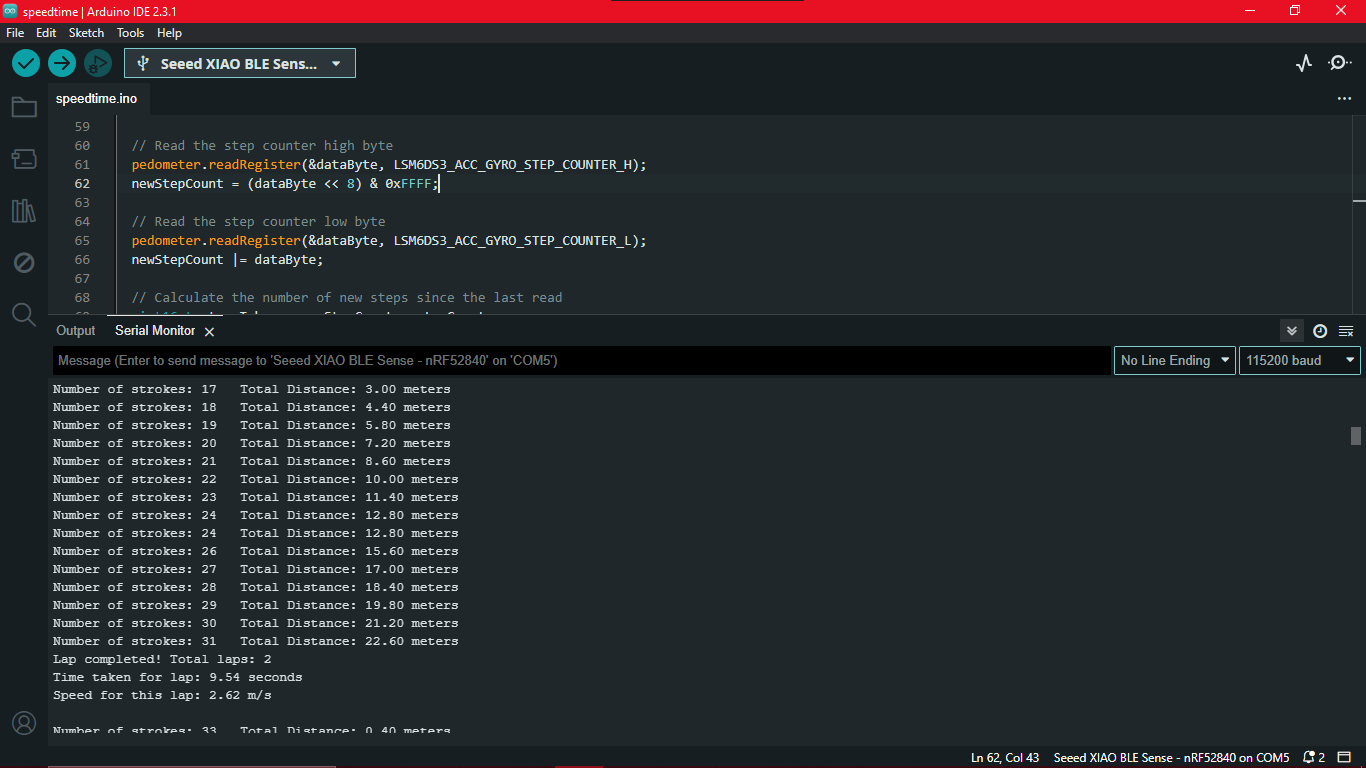
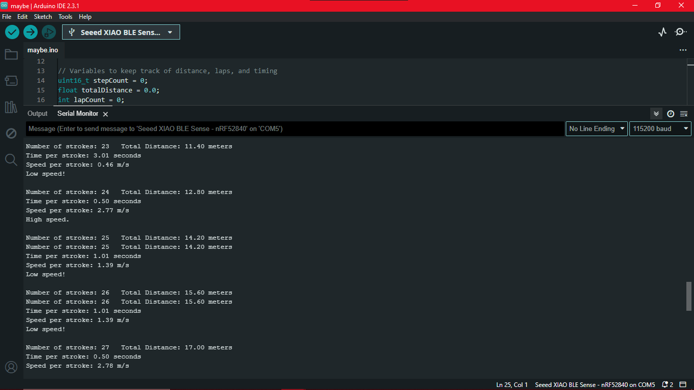
To get high, low and correct speed, the logic is to find the time taken to complete each stroke, calcuate the speed of that instant and compare it with the target speed which will be calculated from target time.
#include "LSM6DS3.h" #include "Wire.h" #include#define CLEAR_STEP true #define NOT_CLEAR_STEP false // Create an instance of the LSM6DS3 class LSM6DS3 pedometer(I2C_MODE, 0x6A); // I2C device address 0x6A #define STROKE_LENGTH_CM 140 // Length of one stroke in centimeters // Variables to keep track of distance, laps, and timing uint16_t stepCount = 0; float totalDistance = 0.0; int lapCount = 0; float poolLength = 25.0; // Set pool length to 25 meters unsigned long lapStartTime = 0; unsigned long lastStrokeTime = 0; // Target speed variables float targetDistance = 50.0; // Distance for the target speed calculation float targetTime = 30.0; // Time in seconds to complete the target distance float targetSpeed = targetDistance / targetTime; // Target speed in m/s void setup() { Serial.begin(9600); while (!Serial); if (pedometer.begin() != 0) { Serial.println("Device error"); } else { Serial.println("Device OK!"); } // Configure LSM6DS3 as pedometer if (0 != config_pedometer(NOT_CLEAR_STEP)) { Serial.println("Configure pedometer fail!"); } else { Serial.println("Success to configure pedometer!"); } // Print the target speed Serial.print("Target speed: "); Serial.print(targetSpeed, 2); Serial.println(" m/s"); // Initialize the start time for the first lap lapStartTime = millis(); lastStrokeTime = millis(); } void loop() { uint8_t dataByte = 0; uint16_t newStepCount = 0; // Read the step counter high byte pedometer.readRegister(&dataByte, LSM6DS3_ACC_GYRO_STEP_COUNTER_H); newStepCount = (dataByte << 8) & 0xFFFF; // Read the step counter low byte pedometer.readRegister(&dataByte, LSM6DS3_ACC_GYRO_STEP_COUNTER_L); newStepCount |= dataByte; // Calculate the number of new steps since the last read uint16_t stepsTaken = newStepCount - stepCount; stepCount = newStepCount; // Update total distance covered (convert cm to meters) totalDistance += (stepsTaken * STROKE_LENGTH_CM) / 100.0; // Check if a lap is completed if (totalDistance >= poolLength) { lapCount++; totalDistance -= poolLength; // Subtract the pool length to get the remaining distance // Calculate time taken and speed for the lap unsigned long lapEndTime = millis(); unsigned long lapTime = lapEndTime - lapStartTime; lapStartTime = lapEndTime; float lapTimeSeconds = lapTime / 1000.0; float speed = poolLength / lapTimeSeconds; Serial.print("Lap completed! Total laps: "); Serial.println(lapCount); Serial.print("Time taken for lap: "); Serial.print(lapTimeSeconds, 2); Serial.println(" seconds"); Serial.print("Speed for this lap: "); Serial.print(speed, 2); Serial.println(" m/s"); Serial.println(); } // Calculate the speed for each stroke if (stepsTaken > 0) { unsigned long currentTime = millis(); float timePerStroke = (currentTime - lastStrokeTime) / 1000.0; lastStrokeTime = currentTime; float speedPerStroke = (STROKE_LENGTH_CM / 100.0) / timePerStroke; Serial.print("Time per stroke: "); Serial.print(timePerStroke, 2); Serial.println(" seconds"); Serial.print("Speed per stroke: "); Serial.print(speedPerStroke, 2); Serial.println(" m/s"); if (speedPerStroke < targetSpeed) { Serial.println("Low speed!"); } else if (speedPerStroke == targetSpeed) { Serial.println("Correct speed."); } else { Serial.println("High speed."); } Serial.println(); } // Print the number of strokes and the total distance covered Serial.print("Number of strokes: "); Serial.print(stepCount-3); Serial.print("\tTotal Distance: "); Serial.print(totalDistance, 2); Serial.println(" meters"); delay(500); } // Setup pedometer mode int config_pedometer(bool clearStep) { uint8_t errorAccumulator = 0; uint8_t dataToWrite = 0; // Temporary variable // Setup the accelerometer dataToWrite = 0; dataToWrite |= LSM6DS3_ACC_GYRO_FS_XL_2g; dataToWrite |= LSM6DS3_ACC_GYRO_ODR_XL_26Hz; // Step 1: Configure ODR-26Hz and FS-2g errorAccumulator += pedometer.writeRegister(LSM6DS3_ACC_GYRO_CTRL1_XL, dataToWrite); // Step 2: Set bit Zen_G, Yen_G, Xen_G, FUNC_EN, PEDO_RST_STEP(1 or 0) if (clearStep) { errorAccumulator += pedometer.writeRegister(LSM6DS3_ACC_GYRO_CTRL10_C, 0x3E); } else { errorAccumulator += pedometer.writeRegister(LSM6DS3_ACC_GYRO_CTRL10_C, 0x3C); } // Step 3: Enable pedometer algorithm errorAccumulator += pedometer.writeRegister(LSM6DS3_ACC_GYRO_TAP_CFG1, 0x40); // Step 4: Step Detector interrupt driven to INT1 pin, set bit INT1_FIFO_OVR errorAccumulator += pedometer.writeRegister(LSM6DS3_ACC_GYRO_INT1_CTRL, 0x10); return errorAccumulator; }
Machine Learning
Seeed Studio XIAO nRF52840 Sense Edge Impulse Getting Started has all the details required on how to set up
using Edge Impulse with Seeed Studio XIAO nRF52840 Sense and how to use the onboard IMU sensor to detect human motion and classify different actions.
I am following this documentation for training some gesture controls for my watch since I don't have a button to control it. Additionally,
I want to train the different swimming movements of my sister to get data about each stroke.
Please open images in new tab to get a clear picture.
.png)
.png)
.png)
.png)
.png)
.png)
Here is the library exported : Yes and No Gesture control
  #include < Yes_and_No_inferencing.h > //replace the library name with yours
  #include "LSM6DS3.h"

  /* Constant defines -------------------------------------------------------- */
  #define CONVERT_G_TO_MS2    9.80665f
  #define MAX_ACCEPTED_RANGE  2.0f        // starting 03/2022, models are generated setting range to +-2, but this example use Arudino library which set range to +-4g. If you are using an older model, ignore this value and use 4.0f instead
  #define INTERVAL_MS (1000 / (FREQUENCY_HZ + 1))
  static unsigned long last_interval_ms = 0;

  LSM6DS3 myIMU(I2C_MODE, 0x6A);  //I2C device address 0x6A

  static bool debug_nn = false; // Set this to true to see e.g. features generated from the raw signal

  /**
  * @brief      Arduino setup function
  */
  void setup()
  {
      // put your setup code here, to run once:
      Serial.begin(115200);
      // comment out the below line to cancel the wait for USB connection (needed for native USB)
      while (!Serial);
      Serial.println("Edge Impulse Inferencing Demo");

      if (!myIMU.begin()) {
          ei_printf("Failed to initialize IMU!\r\n");
      }
      else {
          ei_printf("IMU initialized\r\n");
      }

      if (EI_CLASSIFIER_RAW_SAMPLES_PER_FRAME != 3) {
          ei_printf("ERR: EI_CLASSIFIER_RAW_SAMPLES_PER_FRAME should be equal to 3 (the 3 sensor axes)\n");
          return;
      }
  }

  /**
  * @brief Return the sign of the number
  *
  * @param number
  * @return int 1 if positive (or 0) -1 if negative
  */
  float ei_get_sign(float number) {
      return (number >= 0.0) ? 1.0 : -1.0;
  }

  /**
  * @brief      Get data and run inferencing
  *
  * @param[in]  debug  Get debug info if true
  */
  void loop()
  {
      //ei_printf("\nStarting inferencing in 2 seconds...\n");

      delay(2000);

      //ei_printf("Sampling...\n");

      // Allocate a buffer here for the values we'll read from the IMU
      float buffer[EI_CLASSIFIER_DSP_INPUT_FRAME_SIZE] = { 0 };

      for (size_t ix = 0; ix < EI_CLASSIFIER_DSP_INPUT_FRAME_SIZE; ix += 3) {
          // Determine the next tick (and then sleep later)
          uint64_t next_tick = micros() + (EI_CLASSIFIER_INTERVAL_MS * 1000);

          //IMU.readAcceleration(buffer[ix], buffer[ix + 1], buffer[ix + 2]);

          buffer[ix+0] = myIMU.readFloatAccelX();
          buffer[ix+1] = myIMU.readFloatAccelY();
          buffer[ix+2] = myIMU.readFloatAccelZ();


          for (int i = 0; i < 3; i++) {
              if (fabs(buffer[ix + i]) > MAX_ACCEPTED_RANGE) {
                  buffer[ix + i] = ei_get_sign(buffer[ix + i]) * MAX_ACCEPTED_RANGE;
              }
          }

          buffer[ix + 0] *= CONVERT_G_TO_MS2;
          buffer[ix + 1] *= CONVERT_G_TO_MS2;
          buffer[ix + 2] *= CONVERT_G_TO_MS2;

          delayMicroseconds(next_tick - micros());
      }

      // Turn the raw buffer in a signal which we can the classify
      signal_t signal;
      int err = numpy::signal_from_buffer(buffer, EI_CLASSIFIER_DSP_INPUT_FRAME_SIZE, &signal);
      if (err != 0) {
          ei_printf("Failed to create signal from buffer (%d)\n", err);
          return;
      }

      // Run the classifier
      ei_impulse_result_t result = { 0 };

      err = run_classifier(&signal, &result, debug_nn);
      if (err != EI_IMPULSE_OK) {
          ei_printf("ERR: Failed to run classifier (%d)\n", err);
          return;
      }

      // print the predictions
    // ei_printf("Predictions ");
    // ei_printf("(DSP: %d ms., Classification: %d ms., Anomaly: %d ms.)",
    // result.timing.dsp, result.timing.classification, result.timing.anomaly);
      //ei_printf("\n");
      for (size_t ix = 0; ix < EI_CLASSIFIER_LABEL_COUNT; ix++) {
    // ei_printf("    %s: %.5f\n", result.classification[ix].label, result.classification[ix].value);
      if (result.classification[ix].value > .5) {
          ei_printf("%s \n", result.classification[ix]);
      }
      }

      //  if (result.classification[ix].value > .5) {
      //     ei_printf("    %s: %.5f\n", result.classification[ix].label, result.classification[ix].value);
      // }
      // }


  #if EI_CLASSIFIER_HAS_ANOMALY == 1
      ei_printf("anomaly score: %.3f\n", result.anomaly);
  #endif
  }

  #if !defined(EI_CLASSIFIER_SENSOR) || EI_CLASSIFIER_SENSOR != EI_CLASSIFIER_SENSOR_ACCELEROMETER
  #error "Invalid model for current sensor"
  #endif
However the gestures weren't accurate all the time and there was 1 second delay to predict the gesture. I tried to increase the dataset and tried again but still the results were insatisfactory. However I tried to train different strokes of my sister.
I followed the same steps and here is the library that was generated:
Stroke Detection
The code is same as the previous code except for the change in library. Unfortunately, I forgot to take screenshots of the strokes detected. But I can conclude that this wasn't an effective way to detect the strokes. It was inaccurate most of the time and I had limitations to increase the dataset because I was using a free account. I will not be using this for my project.
PHASE II
Waterproofing
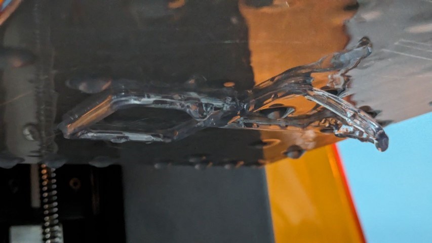
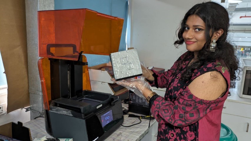
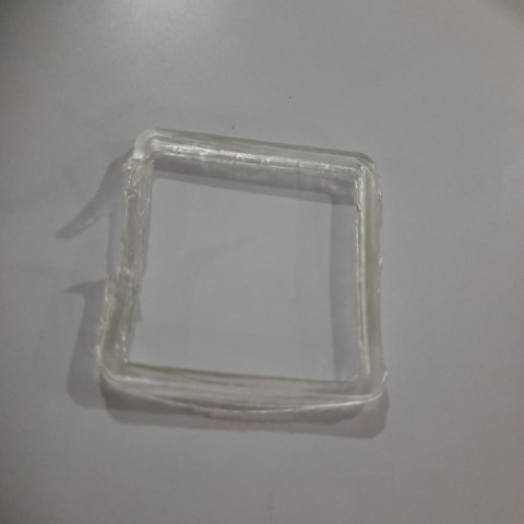
As discussed earlier, gaskets were going to be printed using flexible resin in Formlabs. The print was ready and this is me taking it out for its post-process. Post-process of resin prints must be done using gloves as resin is toxic. It has to be thoroughly washed with IP and then cured in the UV chamber.
Problem
This is the result of the gasket after all post-process. It is deformed. My instructor told me this is due to cupping effect.
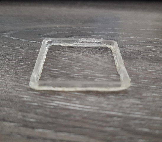
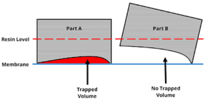
Cupping is a phenomenon inherent to all bottom-up SLA type systems. It occurs when printing a convex shape relative to the build platform. During membrane peel, a vacuum force traps resin in the void, then during return to print position a pressure of resin builds up.
The chances of fixing this problem were less because my gasket was thin and also the material used was close to its expiry. Procuring new material would take weeks. Therefore alternatives to gaskets had to be found out.
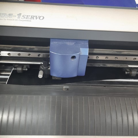
There was 3mm rubber sheet that was available in the lab so the next try was gasket cut in that rubber sheet. Using ZUND the gasket was digitally cut. The watch part was 3d printed again because there was an issue with the USB hitting the part while closing. Also the print before had side hole provisined for USB programming and charging.
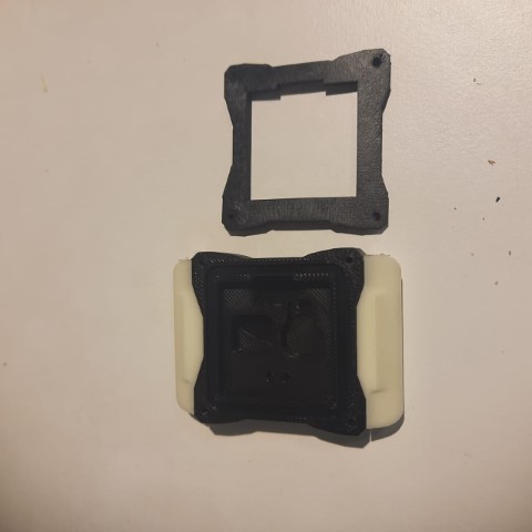
These screws will be tightening the gasket
Problem
The initial plan to waterproof the display was to print a transparent layer along with the top part in
Stratasys 3D printer of the lab. But when it was time to print, there was a problem. It had insufficient white material.
New material could only arrive after a few weeks. So we had a new problem.
As a solution, my instructor Mufeed advised to laser cut acrylic sheet and glue it to the top part. So now it was time to use the Laser to cut the acrylic.
After a few tries of cutting, finally the correct size was obtained.
For better look a black sticker was vinyl cut and stuck on top on the acrylic,
sticking it down would affect the glue.
The rubber gasket was kept in between tightened by the screws. Now its time to test it in water.
BIG PROBLEM
As soon as I put in the water bottle, the water gushed inside immediately. Thankfully it was just a test and I had just kept a damaged oled display inside. But now this problem needed a solution. ASAP.
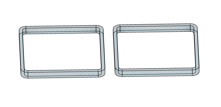
Redesigning GASKET
To reinforce the effectiveness of gasket, it was redesigned to this way. The plan is print this in TPU.
Furthur design changes were added to improve the look of the watch. Thanks a lot to my instructor Mufeed for helping me design.
The parts were printed using three colours- white, black and blue. Unfortunately there was no orange filament in the Lab. The bottom part had to white since I was used RGB LED and the colour had to be visible. But I had mistakenly printed it in black. So I had to print again. Then the display cover was cut in acrylic sheet. Time to waterproof! I gathered all materials.
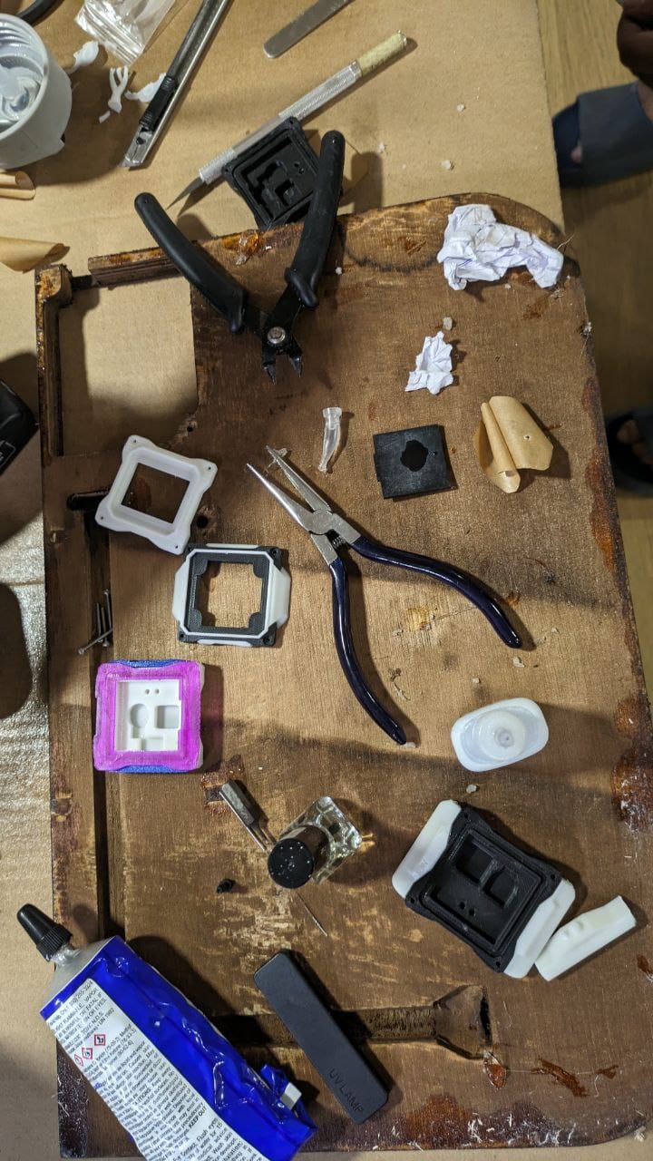
Did you know?
Nail Polish is brilliant choice to waterproof because as it is a liquid it seeps through all the gaps and hardens quickly.
Clear cement joint can be used to strengthen the joint between the acrylic and the case.
Applying clear cement first to secure the joint.
This was kept in UV chamber for 10 minutes for drying. After drying, it was time to test it.
Water was kept in the top part and left for 5 minutes. No water had seep through. And so waterproofing of the top layer was sucessful.
Programming Phase II
I had issues interfacing with OLED libraries. But my instructor Saheen had OLED Library which he told me to try. Thankfully this one worked.
Since gesture control using TinyML wasn't satisfactory, I browsed through ways to use the inbuilt accelerometer to control the watch.
Luckily I stumbled across this thread on the SEEED forums.
It was about implementing double tap interrupts on switch on the different colours of the RGB LED and System off state.
Therefore I will be implementing this logic to turn on timer on my display using double tap interrupts. ALso I will be toggling between red and green colour leds.
  #include "LSM6DS3.h"
  #include "Wire.h"
  #include < U8x8lib.h >

  #define int1Pin PIN_LSM6DS3TR_C_INT1
  #define LEDR 8
  #define LEDG 9
  #define LEDB 10

  LSM6DS3 myIMU(I2C_MODE, 0x6A);
  U8X8_SSD1306_128X64_NONAME_HW_I2C u8x8(/* clock=*/ PIN_WIRE_SCL, /* data=*/ PIN_WIRE_SDA, /* reset=*/ U8X8_PIN_NONE);

  uint8_t interruptCount = 0; // Amount of received interrupts
  uint8_t prevInterruptCount = 0; // Interrupt Counter from last loop
  bool isTiming = false;
  unsigned long startTime = 0;

  void setup() {
      Serial.begin(9600);

      pinMode(LEDR, OUTPUT);
      pinMode(LEDG, OUTPUT);
      pinMode(LEDB, OUTPUT);
      setLedRGB(false, false, true); // set blue led

      myIMU.settings.gyroEnabled = 0; // Gyro currently not used, disabled to save power
      if (myIMU.begin() != 0) {
          Serial.println("IMU error");
      } else {
          Serial.println("IMU OK!");
      }

      setupDoubleTapInterrupt();

      pinMode(int1Pin, INPUT);
      attachInterrupt(digitalPinToInterrupt(int1Pin), int1ISR, RISING);

      u8x8.begin();
      u8x8.setFlipMode(1);
      u8x8.clearDisplay();
      u8x8.setFont(u8x8_font_8x13B_1x2_r);
      u8x8.setCursor(2, 2);
      u8x8.print("Double tap");
  }

  void loop() {
      setLedRGB(false, false, true); // reset led to blue only

      Serial.print("\nInterrupt Counter: ");
      Serial.println(interruptCount);

      // if interrupt was received in this cycle
      if (interruptCount > prevInterruptCount) {
          Serial.println("Interrupt received!");
          if (!isTiming) {
              // Start timing
              startTime = millis();
              isTiming = true;
          } else {
              // Stop timing
              isTiming = false;
          }
          setLedRGB(false, true, false); // set green only
      }

      prevInterruptCount = interruptCount;

      if (isTiming) {
          unsigned long elapsedTime = millis() - startTime;
          displayTime(elapsedTime);
      } else {
          u8x8.clearDisplay();
          u8x8.setCursor(2, 2);
          u8x8.print("Double tap");
      }

      delay(500);
  }

  // -------------------- Interrupts ------------------------- //

  void setupDoubleTapInterrupt() {
      // Configuration for Double Tap
      myIMU.writeRegister(LSM6DS3_ACC_GYRO_CTRL1_XL, 0x60);
      myIMU.writeRegister(LSM6DS3_ACC_GYRO_TAP_CFG1, 0x8E); // INTERRUPTS_ENABLE, SLOPE_FDS
      myIMU.writeRegister(LSM6DS3_ACC_GYRO_TAP_THS_6D, 0x8C);
      myIMU.writeRegister(LSM6DS3_ACC_GYRO_INT_DUR2, 0x7F);
      myIMU.writeRegister(LSM6DS3_ACC_GYRO_WAKE_UP_THS, 0x80);
      myIMU.writeRegister(LSM6DS3_ACC_GYRO_MD1_CFG, 0x08);
  }

  void int1ISR() {
      interruptCount++;

  }

  // -------------------- Utilities ------------------------- //

  void setLedRGB(bool red, bool green, bool blue) {
      if (!blue) { digitalWrite(LEDB, HIGH); } else { digitalWrite(LEDB, LOW); }
      if (!green) { digitalWrite(LEDG, HIGH); } else { digitalWrite(LEDG, LOW); }
      if (!red) { digitalWrite(LEDR, HIGH); } else { digitalWrite(LEDR, LOW); }
  }

  void displayTime(unsigned long time) {
      int milliseconds = time % 1000;
      int seconds = (time / 1000) % 60;
      int minutes = (time / 60000) % 60;

      u8x8.clearDisplay();
      u8x8.setCursor(3, 2);
      u8x8.print("");
      if (minutes < 10) {
          u8x8.print("0");
      }
      u8x8.print(minutes);
      u8x8.print(":");
      if (seconds < 10) {
          u8x8.print("0");
      }
      u8x8.print(seconds);
      u8x8.print(":");
      if (milliseconds < 100) {
          u8x8.print("0");
      }
      if (milliseconds < 10) {
          u8x8.print("0");
      }
      u8x8.print(milliseconds);
  }
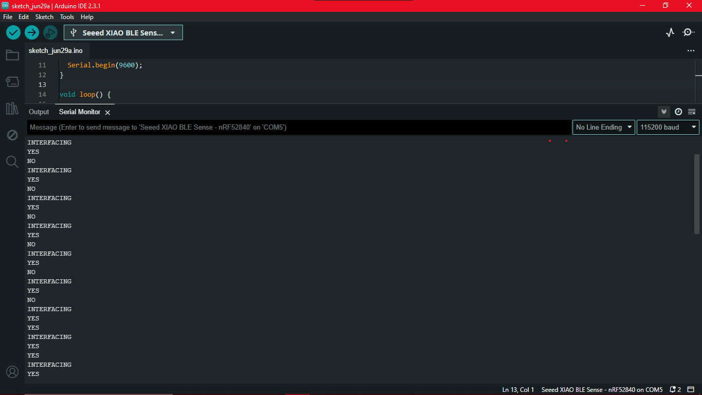
Without TinyML gesture training, I had to find a way to add few gesture recognitions for watch control. I thought of incorporated the roll gesture. So in robotics, ROLL-PITCH-YAW are Degrees of Freedom of a robot.
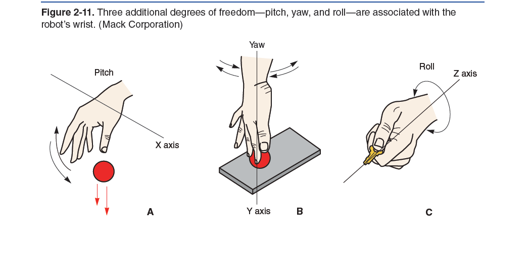
Here is the thread and reference I used for the code. The code identifies no movement as idle, clockwise movement as no and anti-clockwise movement as yes.
      #include < LSM6DS3.h > // https://github.com/Seeed-Studio/Seeed_Arduino_LSM6DS3
      #include < Wire.h >

      LSM6DS3 lsm6ds33(I2C_MODE, 0x6A); // I2C device address 0x6A

      float accelX, accelY, accelZ;               // units m/s/s i.e. accelZ if often 9.8 (gravity)
      float gyroX, gyroY, gyroZ;                  // units dps (degrees per second)
      float gyroDriftX, gyroDriftY, gyroDriftZ;   // units dps
      float gyroRoll, gyroPitch, gyroYaw;         // units degrees (expect major drift)
      float complementaryRoll, complementaryPitch, complementaryYaw; // units degrees (excellent roll, pitch, yaw minor drift)

      long lastTime;
      long lastInterval;

      const int rollThreshold = 2; // Adjust these thresholds according to your specific scenario
      const int pitchThreshold = 0;
      const int yawThreshold = 0;

      enum Movement { NO_MOVEMENT, CLOCKWISE, ANTICLOCKWISE };

      Movement detectMovement(int roll, int pitch, int yaw) {
        if (abs(roll) > rollThreshold)
          return (roll > 0) ? ANTICLOCKWISE : CLOCKWISE;
      }


      bool readIMU() {
        accelX = lsm6ds33.readFloatAccelX();
        accelY = lsm6ds33.readFloatAccelY();
        accelZ = lsm6ds33.readFloatAccelZ();
        gyroX = lsm6ds33.readFloatGyroX();
        gyroY = lsm6ds33.readFloatGyroY();
        gyroZ = lsm6ds33.readFloatGyroZ();
        return true;
      }

      void calibrateIMU(int delayMillis, int calibrationMillis) {
        int calibrationCount = 0;

        delay(delayMillis);

        float sumX = 0, sumY = 0, sumZ = 0;
        int startTime = millis();
        while (millis() < startTime + calibrationMillis) {
          if (readIMU()) {
            sumX += gyroX;
            sumY += gyroY;
            sumZ += gyroZ;

            calibrationCount++;
          }
        }

        if (calibrationCount == 0) {
          Serial.println("Failed to calibrate");
        }

        gyroDriftX = sumX / calibrationCount;
        gyroDriftY = sumY / calibrationCount;
        gyroDriftZ = sumZ / calibrationCount;
      }

      void doImuCalculations() {
        complementaryRoll = complementaryRoll + ((gyroX - gyroDriftX) / lastInterval);
        complementaryPitch = complementaryPitch + ((gyroY - gyroDriftY) / lastInterval);
        complementaryYaw = complementaryYaw + ((gyroZ - gyroDriftZ) / lastInterval);

        complementaryRoll = 0.98 * complementaryRoll;
        complementaryPitch = 0.98 * complementaryPitch;
        complementaryYaw = 0.98 * complementaryYaw;
      }

      void setup() {
        Serial.begin(9600);

        if (lsm6ds33.begin() != 0) {
          Serial.println("Device error");
        } else {
          Serial.println("Device OK!");
        }

        calibrateIMU(250, 250);
      }

      void loop() {
        if (readIMU()) {
          long currentTime = millis();
          lastInterval = currentTime - lastTime;
          lastTime = currentTime;

          doImuCalculations();

          int roll = map(complementaryRoll, -180, 180, -90, 90);
          int pitch = map(complementaryPitch, -180, 180, -90, 90);
          int yaw = map(complementaryYaw, -180, 180, -90, 90);

          Movement movement = detectMovement(roll, pitch, yaw);

          switch (movement) {
            case NO_MOVEMENT:
              Serial.println("IDLE");
              break;
            case CLOCKWISE:
              Serial.println("NO");
              break;
            case ANTICLOCKWISE:
              Serial.println("YES");
              break;
          }

          delay(100); // Adjust delay as needed to control the frequency of readings
        }
      }
I tried to operate the motor in different modes using PWM to find out which one had the best effect. There is constant vibration, Intermittent vibration and pulse vibration.
      #define VibrationMotorPin D3

      void setup() {
        pinMode(VibrationMotorPin, OUTPUT);
      }

      void loop() {
        // Mode 1: Constant vibration
        digitalWrite(VibrationMotorPin, HIGH);
        delay(2000); // Vibrate for 2 seconds
        digitalWrite(VibrationMotorPin, LOW);
        delay(2000); // Wait for 2 seconds

        // Mode 2: Intermittent vibration
        for (int i = 0; i < 5; i++) {
          digitalWrite(VibrationMotorPin, HIGH);
          delay(500); // Vibrate for 0.5 seconds
          digitalWrite(VibrationMotorPin, LOW);
          delay(500); // Wait for 0.5 seconds
        }
        delay(2000); // Wait for 2 seconds

        // Mode 3: Pulse vibration
        for (int i = 0; i < 3; i++) {
          digitalWrite(VibrationMotorPin, HIGH);
          delay(200); // Vibrate for 0.2 seconds
          digitalWrite(VibrationMotorPin, LOW);
          delay(200); // Wait for 0.2 seconds
        }
        delay(2000); // Wait for 2 seconds
      }
There's no video because nothing is actually visible. However, constant vibration draws a lot of current and is very noisy. Pulse vibration is very quick and faint almost cannot be felt. What I think worked best was Intermittent vibration, it had vibrations of medium intensity.
Now it's time to integrate all these codes. I'll explain the the full working here.
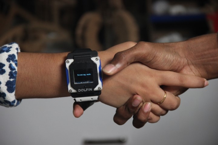
When the watch is on, it displays Swimming Mode.
Double tapping, will start the timer. If you wrist roll while the timer is on, it displays the current lap you're swimming.
Also the LED colours represent the speed zones, Red means low speed, green means right speed, and blue means high speed.
For now the target time is hard-coded to 30s. So when that elapses, the motor vibrates.
Double tap to stop the timer while swimming. Double tap again to restart the timer.
TO reset all values, wrist roll while the timer is set to zero.
      #include "LSM6DS3.h"
      #include "Wire.h"
      #include < U8x8lib.h >

      #define int1Pin PIN_LSM6DS3TR_C_INT1
      #define LEDR 9
      #define LEDG 10
      #define LEDB 11
      #define MOTOR_PIN 3 // Define the motor pin
      #define CLEAR_STEP      true
      #define NOT_CLEAR_STEP  false

      LSM6DS3 myIMU(I2C_MODE, 0x6A);
      U8X8_SSD1306_128X64_NONAME_HW_I2C u8x8(/* clock=*/ PIN_WIRE_SCL, /* data=*/ PIN_WIRE_SDA, /* reset=*/ U8X8_PIN_NONE);

      LSM6DS3 pedometer(I2C_MODE, 0x6A);    // I2C device address 0x6A

      #define STROKE_LENGTH_CM 140  // Length of one stroke in centimeters

      // Variables to keep track of distance, laps, and timing
      uint16_t stepCount = -5;
      float totalDistance = 0.0;
      int lapCount = 0;
      float poolLength = 25.0;  // Set pool length to 25 meters
      unsigned long lapStartTime = 0;
      unsigned long lastStrokeTime = 0;

      // Target speed variables
      float targetDistance = 50.0; // Distance for the target speed calculation
      float targetTime = 30.0; // Time in seconds to complete the target distance
      float targetSpeed = targetDistance / targetTime; // Target speed in m/s

      enum State { START, SWIMMING, STOP };
      State currentState = START;
      uint8_t interruptCount = 0;
      unsigned long startTime = 0;
      bool isTiming = false;

      float gyroX, gyroY, gyroZ;                  // units dps (degrees per second)
      float gyroDriftX, gyroDriftY, gyroDriftZ;   // units dps
      float complementaryRoll = 0, complementaryPitch = 0, complementaryYaw = 0; // units degrees (excellent roll, pitch, yaw minor drift)

      long lastTime = 0;
      long lastInterval = 0;

      const int rollThreshold = 2; // Adjust these thresholds according to your specific scenario
      const int pitchThreshold = 0;
      const int yawThreshold = 0;

      const unsigned long targetTimeMillis = 30000; // Target time in milliseconds (30 seconds)
      bool targetTimeReached = false; // Flag to check if target time is reached

      enum Movement { NO_MOVEMENT, CLOCKWISE, ANTICLOCKWISE };

      void setup() {
          Serial.begin(9600);

          pinMode(LEDR, OUTPUT);
          pinMode(LEDG, OUTPUT);
          pinMode(LEDB, OUTPUT);
          pinMode(MOTOR_PIN, OUTPUT); // Initialize motor pin
          setLedRGB(false, false, false); // set blue led

          myIMU.settings.gyroEnabled = 1; // Enable gyroscope
          if (myIMU.begin() != 0) {
              Serial.println("IMU error");
          } else {
              Serial.println("IMU OK!");
          }

          setupDoubleTapInterrupt();

          pinMode(int1Pin, INPUT);
          attachInterrupt(digitalPinToInterrupt(int1Pin), int1ISR, RISING);

          u8x8.begin();
          u8x8.setFlipMode(1);
          u8x8.clearDisplay();
          u8x8.setCursor(1, 4);
          u8x8.setFont(u8x8_font_8x13B_1x2_r);

          displayMessage("Swimming Mode");

          calibrateIMU(250, 250);
          lastTime = millis(); // Initialize lastTime

          if (pedometer.begin() != 0)
        {
          Serial.println("Device error");
        } else
        {
          Serial.println("Device OK!");
        }

        // Configure LSM6DS3 as pedometer
        if (0 != config_pedometer(NOT_CLEAR_STEP))
        {
          Serial.println("Configure pedometer fail!");
        } else
        {
          Serial.println("Success to configure pedometer!");
        }

        // Print the target speed
        Serial.print("Target speed: ");
        Serial.print(targetSpeed, 2);
        Serial.println(" m/s");

        // Initialize the start time for the first lap
        lapStartTime = millis();
        lastStrokeTime = millis();
      }

      void loop()
      {
        uint8_t dataByte = 0;
        uint16_t newStepCount = 0;

        // Read the step counter high byte
        pedometer.readRegister(&dataByte, LSM6DS3_ACC_GYRO_STEP_COUNTER_H);
        newStepCount = (dataByte << 8) & 0xFFFF;

        // Read the step counter low byte
        pedometer.readRegister(&dataByte, LSM6DS3_ACC_GYRO_STEP_COUNTER_L);
        newStepCount |= dataByte;

        // Calculate the number of new steps since the last read
        uint16_t stepsTaken = newStepCount - stepCount;

        stepCount = newStepCount;

        // Update total distance covered (convert cm to meters)
        totalDistance += (stepsTaken * STROKE_LENGTH_CM) / 100.0;

        if (isTiming) {
          // Check if a lap is completed
          if (totalDistance >= poolLength) {
            lapCount++;
            totalDistance -= poolLength;  // Subtract the pool length to get the remaining distance

            // Calculate time taken and speed for the lap
            unsigned long lapEndTime = millis();
            unsigned long lapTime = lapEndTime - lapStartTime;
            lapStartTime = lapEndTime;

            float lapTimeSeconds = lapTime / 1000.0;
            float speed = poolLength / lapTimeSeconds;

            Serial.print("Lap completed! Total laps: ");
            Serial.println(lapCount);
            Serial.print("Time taken for lap: ");
            Serial.print(lapTimeSeconds, 2);
            Serial.println(" seconds");
            Serial.print("Speed for this lap: ");
            Serial.print(speed, 2);
            Serial.println(" m/s");
            Serial.println();
          }

          // Calculate the speed for each stroke
          if (stepsTaken > 0) {
            unsigned long currentTime = millis();
            float timePerStroke = (currentTime - lastStrokeTime) / 1000.0;
            lastStrokeTime = currentTime;

            float speedPerStroke = (STROKE_LENGTH_CM / 100.0) / timePerStroke;

            Serial.print("Time per stroke: ");
            Serial.print(timePerStroke, 2);
            Serial.println(" seconds");
            Serial.print("Speed per stroke: ");
            Serial.print(speedPerStroke, 2);
            Serial.println(" m/s");

            if (speedPerStroke < targetSpeed) {
              Serial.println("Low speed!");
              digitalWrite(LEDR, HIGH);
              digitalWrite(LEDG, LOW);
              digitalWrite(LEDB, LOW);
            } else if (speedPerStroke == targetSpeed) {
              Serial.println("Correct speed.");
              digitalWrite(LEDR, LOW);
              digitalWrite(LEDG, HIGH);
              digitalWrite(LEDB, LOW);
            } else {
              Serial.println("High speed.");
              digitalWrite(LEDR, LOW);
              digitalWrite(LEDG, LOW);
              digitalWrite(LEDB, HIGH);
            }
            Serial.println();
          }

          // Print the number of strokes and the total distance covered
          Serial.print("Number of strokes: ");
          Serial.print(stepCount);
          Serial.print("\tTotal Distance: ");
          Serial.print(totalDistance, 2);
          Serial.println(" meters");

          // Check if target time is reached
          if (millis() - startTime >= targetTimeMillis) {
            targetTimeReached = true;
            triggerVibration();
          }
        }

        delay(500);
      }

      // Setup pedometer mode
      int config_pedometer(bool clearStep)
      {
        uint8_t errorAccumulator = 0;
        uint8_t dataToWrite = 0;  // Temporary variable

        // Setup the accelerometer
        dataToWrite = 0;

        dataToWrite |= LSM6DS3_ACC_GYRO_FS_XL_2g;
        dataToWrite |= LSM6DS3_ACC_GYRO_ODR_XL_26Hz;

        // Step 1: Configure ODR-26Hz and FS-2g
        errorAccumulator += pedometer.writeRegister(LSM6DS3_ACC_GYRO_CTRL1_XL, dataToWrite);

        // Step 2: Set bit Zen_G, Yen_G, Xen_G, FUNC_EN, PEDO_RST_STEP(1 or 0)
        if (clearStep)
        {
          errorAccumulator += pedometer.writeRegister(LSM6DS3_ACC_GYRO_CTRL10_C, 0x3E);
        } else
        {
          errorAccumulator += pedometer.writeRegister(LSM6DS3_ACC_GYRO_CTRL10_C, 0x3C);
        }

        // Step 3: Enable pedometer algorithm
        errorAccumulator += pedometer.writeRegister(LSM6DS3_ACC_GYRO_TAP_CFG1, 0x40);

        // Step 4: Step Detector interrupt driven to INT1 pin, set bit INT1_FIFO_OVR
        errorAccumulator += pedometer.writeRegister(LSM6DS3_ACC_GYRO_INT1_CTRL, 0x10);

        return errorAccumulator;
      }

      void displayMessage(const char* message) {
          u8x8.clearDisplay();
          u8x8.setCursor(2, 2);
          u8x8.print(message);
      }

      void displayTime(unsigned long time) {
          int milliseconds = time % 1000;
          int seconds = (time / 1000) % 60;
          int minutes = (time / 60000) % 60;

          u8x8.clearDisplay();
          u8x8.setCursor(3, 2);
          if (minutes < 10) {
              u8x8.print("0");
          }
          u8x8.print(minutes);
          u8x8.print(":");
          if (seconds < 10) {
              u8x8.print("0");
          }
          u8x8.print(seconds);
          u8x8.print(":");
          if (milliseconds < 100) {
              u8x8.print("0");
          }
          if (milliseconds < 10) {
              u8x8.print("0");
          }
          u8x8.print(milliseconds);
      }

      Movement detectMovement(int roll, int pitch, int yaw) {
          if (abs(roll) > rollThreshold)
              return (roll > 0) ? ANTICLOCKWISE : CLOCKWISE;
          return NO_MOVEMENT;
      }

      bool readIMU() {
          gyroX = myIMU.readFloatGyroX();
          gyroY = myIMU.readFloatGyroY();
          gyroZ = myIMU.readFloatGyroZ();

          Serial.print("GyroX: ");
          Serial.print(gyroX);
          Serial.print(" GyroY: ");
          Serial.print(gyroY);
          Serial.print(" GyroZ: ");
          Serial.println(gyroZ);

          return true;
      }

      void calibrateIMU(int delayMillis, int calibrationMillis) {
          int calibrationCount = 0;

          delay(delayMillis);

          float sumX = 0, sumY = 0, sumZ = 0;
          int startTime = millis();
          while (millis() < startTime + calibrationMillis) {
              if (readIMU()) {
                  sumX += gyroX;
                  sumY += gyroY;
                  sumZ += gyroZ;

                  calibrationCount++;
              }
          }

          if (calibrationCount == 0) {
              Serial.println("Failed to calibrate");
              return;
          }

          gyroDriftX = sumX / calibrationCount;
          gyroDriftY = sumY / calibrationCount;
          gyroDriftZ = sumZ / calibrationCount;
      }

      void doImuCalculations() {
          if (lastInterval > 0) {
              float deltaTime = lastInterval / 1000.0; // Convert ms to s
              complementaryRoll += ((gyroX - gyroDriftX) * deltaTime);
              complementaryPitch += ((gyroY - gyroDriftY) * deltaTime);
              complementaryYaw += ((gyroZ - gyroDriftZ) * deltaTime);

              complementaryRoll = 0.98 * complementaryRoll + 0.02 * (gyroX - gyroDriftX);
              complementaryPitch = 0.98 * complementaryPitch + 0.02 * (gyroY - gyroDriftY);
              complementaryYaw = 0.98 * complementaryYaw + 0.02 * (gyroZ - gyroDriftZ);
          }
      }

      void triggerVibration() {
          for (int i = 0; i < 5; i++) {
              digitalWrite(MOTOR_PIN, HIGH);
              delay(100); // Adjust pulse duration as needed
              digitalWrite(MOTOR_PIN, LOW);
              delay(100); // Adjust pause duration as needed
          }
      }

      // Interrupt service routine for double tap
      void int1ISR() {
          if (currentState == START) {
              currentState = SWIMMING;
              startTime = millis();
              lapStartTime = startTime;
              lastStrokeTime = startTime;
              displayMessage("Swimming...");
              isTiming = true;
              Serial.println("Timer started.");
          } else if (currentState == SWIMMING) {
              currentState = STOP;
              displayMessage("Paused");
              isTiming = false;
              Serial.println("Timer stopped.");
          } else if (currentState == STOP) {
              currentState = SWIMMING;
              startTime = millis();
              lapStartTime = startTime;
              lastStrokeTime = startTime;
              displayMessage("Swimming...");
              isTiming = true;
              Serial.println("Timer restarted.");
          }
      }

      void setLedRGB(bool red, bool green, bool blue) {
          digitalWrite(LEDR, red ? LOW : HIGH);
          digitalWrite(LEDG, green ? LOW : HIGH);
          digitalWrite(LEDB, blue ? LOW : HIGH);
      }
The working can be seen in the presentation video.
PHASE III
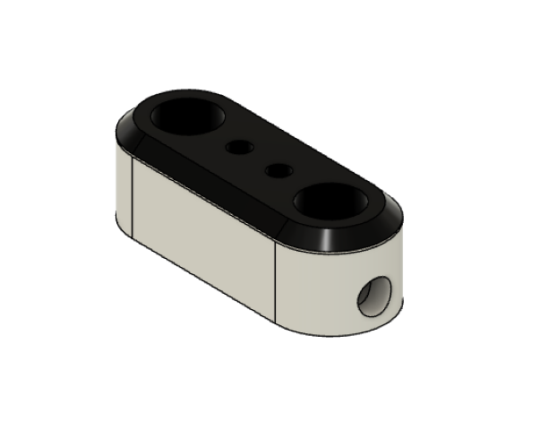
Charger Making
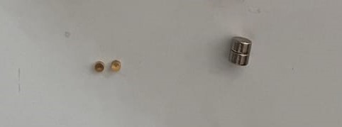
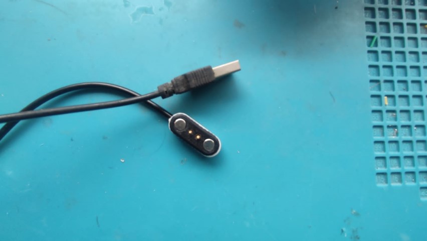
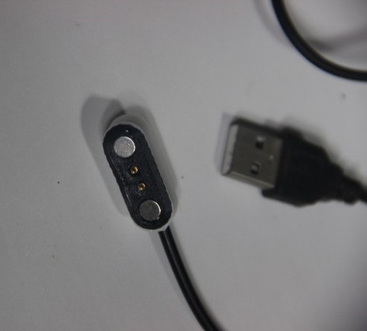
To waterproof the watch, I'm using POGO pins and disc as a charger. I had already shown the 3D design above. Now it's time to print it and make the charger. So I took a USB cable with 2 contact- live wire and ground wire. Cut the cable to solder the wires to the POGO pins inserted to the charging case. While inserting magnet to the case, ensure that both the magnets are of opposite poles.
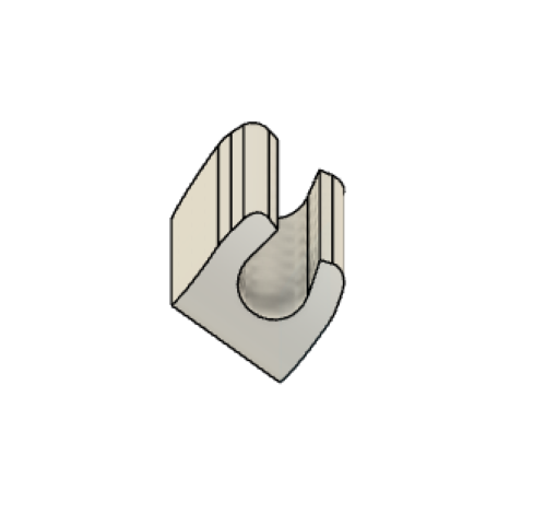
Strap Making
I already had the strap but to make the project completely built at FabLab Kerala, strap will be made by ZUND cutting in 3mm rubber sheet.
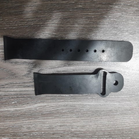
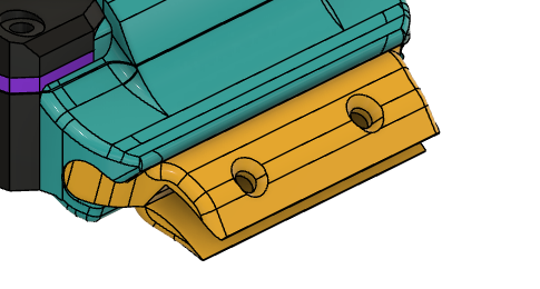
This rubber strap was loose for printed watch case. So here's a strap holder which can be fitted with rubber strap for the same case.
Final Render
Here's the final look of the watch


The exported file is greater than 10mb even after zipping it. so here's the link to it.
Fusion FileAssembly
Waterproofing- The final test
Now that full watch was ready. It was time to dip it in water and see the result.
It works! DOLFIN is done!
BOM
| SL No | Material | Amount | Place of Procurement |
|---|---|---|---|
| 1 | Seeed XIAO nRF52840 Sense | ₹1,899.00 | Lab |
| 2 | 0.96 Inch I2C/IIC 4-Pin OLED Display Module | ₹162.00 | Lab |
| 3 | 40 mAh 3.7V single cell Rechargeable LiPo Battery | ₹119.00 | Penta Menaka |
| 4 | LED RGB CLEAR 4PLCC SMD | ₹19.00 | Lab |
| 5 | Coin vibration motor | ₹100.00 | Penta Menaka |
| 6 | eSun ePLA+HS 3D Printing Filament- 1.75mm White | ₹299.00 (3 hours) | Lab |
| 7 | 3D Printing Filament Black PLA | ₹199.00 (2 hours) | Lab |
| 8 | SeSun eTPU-95A 3D Printing Filament-Transparent Purple | ₹99.00 (1 hour) | Lab |
| 9 | M2 nut and bolt x 20mm | ₹200 | Lab |
| 10 | 3mm Waterproof Rubber Sheet | ₹50 | Lab |
| Total | ₹3,146.00 | ||
| Personal Expenses | ₹220.00 | ||
Adding the license
I chose this license.
Adding to the footer of my final project page and the presentation slide.
More details in week 18
PRESENTATION VIDEO
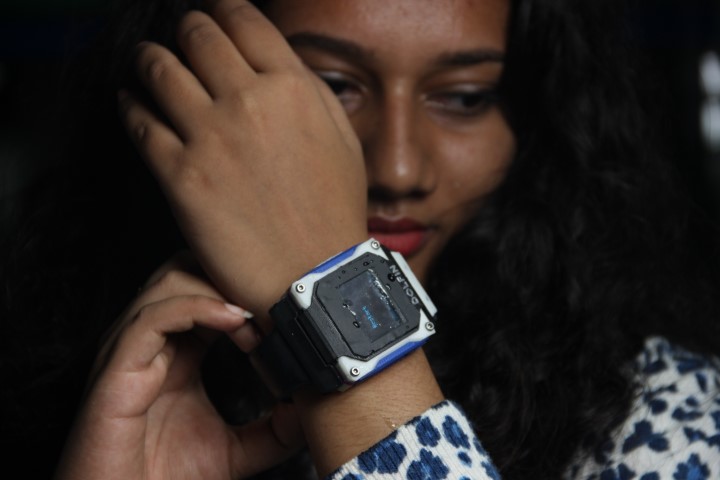
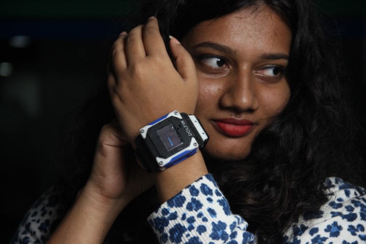
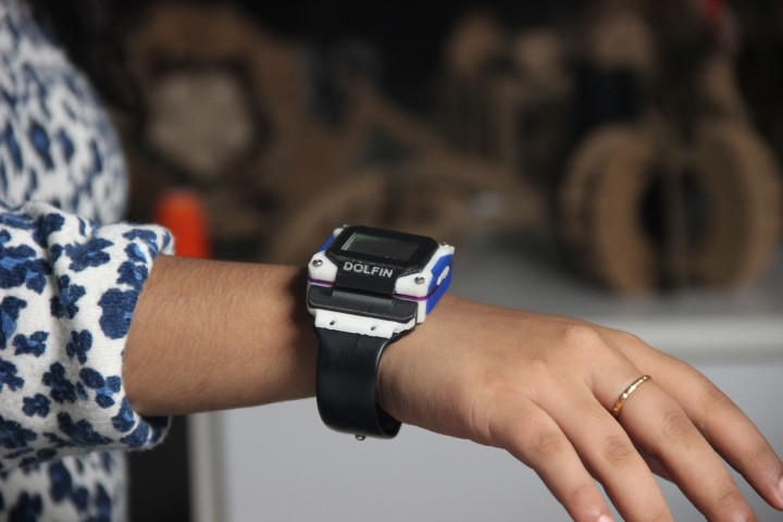
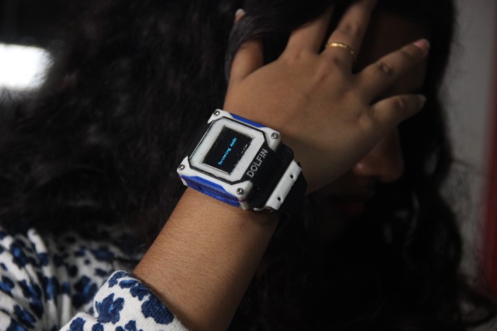
PHOTOSHOOT

Gratitude
I want to extend my heartfelt gratitude to everyone who supported me in the creation of DOLFIN. This journey was challenging, but I was fortunate to have the unwavering support and guidance of my instructors throughout the project. A special thanks to Mufeed, Saheen, and Jogin for your wholehearted support and sleepless nights. To all my FAB mates, thank you for being part of this journey. These past six months have flown by, but we were together every step of the way, learning and growing.