Scroll to Top
CAD

Computer-Aided Design


Individual Assignment

  • 1. Model (raster, vector, 2D, 3D, render, animate, simulate, ...) a possible final project,

  • 2. Compress your images and videos

  • 3. Post a description with your design files on your class page

2D Design


What is Raster?

Raster refers to a graphic representation stored as a grid of pixels, each containing color information. Common formats include JPEG and PNG. Unlike vector graphics, resizing raster images can lead to quality loss due to pixel interpolation. Raster images are suitable for detailed graphics and photographs.

Project Management

Raster tools

Raster tools like Photoshop, GIMP, and Photopea are powerful graphic editors used for manipulating pixel-based images. Adobe Photoshop, an industry-standard, offers extensive features for photo editing and design. GIMP, an open-source alternative, provides robust capabilities. Photopea, an online tool, offers Photoshop-like functionality in a browser, making image editing accessible.


Photopea

Photopea is a versatile online raster graphics editor, resembling Photoshop, offering accessible image editing features directly in a web browser.

I utilized Photopea to get acquainted with its features and edit a PSD file.


  1. Open browser and search for www.photopea.com
  2. Project Management

  3. I thought of a poster for my final project, so I visited freepik.com for some templates
  4. Project Management

  5. I opened the psd file of the template in Photopea. I made some edits to it, however as a Photoshop user I decided to make full edits in Photoshop.
  6. Project Management

  7. Since the template lacked the watch image, I decided to edit a mockup template of smart watch in Photopea and export it.
  8. Project Management


Photoshop

Photoshop, an industry-standard raster graphics editor, offers powerful tools for image editing, design, and manipulation, widely used for creative projects.

I used Photoshop to edit a PSD file and design a poster for the Aquasense smart swim watch project, employing its versatile features for effective graphic creation.


  1. I opened the psd file of the poster template in Photoshop.
  2. Project Management

  3. The font Kenyan-Coffee wasnt installed in my pc, so I browsed for it and installed it.
  4. Project Management

  5. I edited the template to feature my final project, AquaSense. I added the watch which was exported from Photopea.
  6. Project Management

  7. I added the logo which was made in edited in Inkscape.
  8. Project Management

  9. As I zoomed in on the logo, it became very pixelated as it was a raster.
  10. raster

  11. I added the second logo on the watch which was made in Inkscape.
  12. raster

  13. Since the poster was to feature my final project, I added the features I have planned to the poster and a one-liner about the project. Here's the poster:
  14. raster


GIMP

GIMP, a robust open-source raster graphics editor, provides powerful tools for image editing, retouching, and design, offering versatile functionality for creatives.

I used GIMP for creating mockups with the logos I had created/edited from Inkscape.


  1. I opened GIMP and was very intrigued by its workspace. It had most of the functionalities of Photoshop and I just had to navigate myself to the different tools and get familiarised with the workspace. I refered a video on how to make logo mockups on a t-shirt and decided to do the same.
  2. eg

  3. I added the first logo and blend it with the t-shirt and it looked natural
  4. eg

  5. Then, I changed the tshirt colour by adding another layer and filling it with yellow. Then from blend option, I selected multiply and the shirt became yellow.
  6. eg

  7. For the next mockup I thought of creating a mockup of watch display design I had created in Figma. I took this image of a swimmer wearing a smartwatch and opened it in GIMP along with the display design.
  8. eg

  9. Since the watch display of the image already had a design, I removed it.
  10. eg

  11. Then I took my design and tried to fit it inside the watch area.. For the perfect fitting, I used the perspective transform, and the display was well-fit into the watch.
  12. eg

  13. Here's the final result:
  14. eg


What is Vector?

A vector refers to a graphic representation using mathematical equations, allowing for scalable and lossless resizing. Unlike raster images, vectors maintain quality regardless of size, ideal for logos and illustrations.


Vector tools

Vector tools like Inkscape and Illustrator are essential for precise graphic design. Inkscape, an open-source software, provides versatile vector editing. Adobe Illustrator, an industry-standard, offers advanced features for professionals. Both empower users to create scalable, high-quality graphics, logos, and illustrations with precision and flexibility in their design workflows.


Inkscape

Inkscape is a free and open-source vector graphics editor. It provides a powerful set of tools for creating and editing scalable vector graphics (SVG) and is suitable for tasks such as illustration, logo design, and general vector-based artwork. Inkscape is available for various operating systems, including Windows, macOS, and Linux.

I employed Inkscape, a potent open-source vector tool, to meticulously design a scalable logo for Aquasense.

These resources were used for the Inkscape tutorial.

Introduction to Inkscape: Inkscape Explained in 5 Minutes

Logo Design: Inkscape Beginner Tutorial of Simple Letter Logos


  1. I've primarily worked with Illustrator for vector graphics, but after watching an introductory video on Inkscape, I noticed its similarities to Illustrator. Encouraged by this, I've decided to give Inkscape a try. I've begun by downloading the software and am eager to explore its features for the first time.
  2. Project Management


  3. Next, I followed the video to create a letter logo with A and S which stands for AquaSense. After following a series of steps from the video, I was able to transform letters seperately as an object. I manipulated the arms of S by elongating it and resized it to fit into A whilst overlapping it.
  4. eg

  5. Then, I created a duplicate of the letters and created outset three times. Next, using the shapebuilder tool I morphed the letters to sleek look.
  6. Project Management

  7. The selected path in blue will be visible and the path in grey will be deleted.
  8. Project Management

  9. Here's the logo in its final form after I coloured the letters using the fill
  10. Project Management

  11. Next, I thought of trying out the bitmap trace feature of Inkscape. For that I took a logo which was generated from Microsoft Designer and vectorised it using bitmap trace.
  12. Project Management

  13. Bitmap trace has a lot of options so I played around with scans options and got different results. For example: here's a trace with 8 colours.
  14. Project Management

  15. Here's a trace with 4 colours.
  16. Project Management

  17. Here's the trace when I ungrouped the vector.
  18. Project Management

  19. I repeated the same procedure for another logo which was generated by Microsoft Designer.
  20. Project Management

  21. The logo after tracing and colouring.
  22. vector

  23. The logo quality is maintained even when I zoomed in since this is a vector.
  24. vector

  25. Here's the logo after a few colouring I did using fill.
  26. vector


Figma

Figma is a collaborative web-based design and prototyping tool. It allows multiple users to work simultaneously on the same project, fostering real-time collaboration among designers. Figma is popular for its versatility, ease of use, and the ability to create interactive prototypes, making it a valuable tool for UX/UI design.


I used Figma for designing the display interface of AquaSense. Having previous experience in Figma for UI/UX Design, this was the easiest part of this week's assignment.

eg

  1. From figma community, I found a few smart watch templates which I'll be using be for text fonts and icons. For the design, I'll be using my sketch.
  2. eg

  3. I followed my sketch for the display design.
  4. eg

  5. I made a few changes to my sketch while designing such as I added an oxygen level widget and a speed measurement widget.
  6. eg

  7. Here's the final design:
  8. eg


3D Modelling


3D modeling is the process of creating a three-dimensional representation of an object or scene using specialized computer software. It involves defining the shape and appearance of objects in a virtual 3D space, considering aspects like geometry, texture, and materials. 3D models can be used for various purposes, including animations, simulations, virtual reality, video games, and manufacturing. Artists, designers, engineers, and architects commonly use 3D modeling to visualize and communicate their ideas, simulate real-world conditions, and create digital prototypes before physical production.

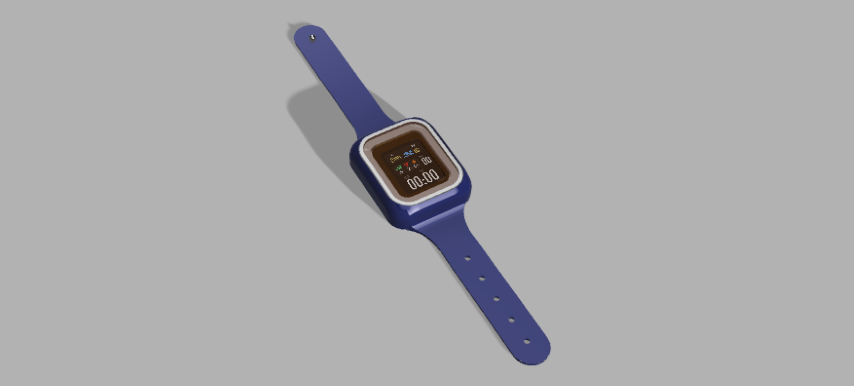
During this week, our focus was on familiarsing with atleast three CAD tools and create a possible design of final project.


What is Fusion 360?

Fusion 360, developed by Autodesk, is a cloud-based 3D CAD, CAM, and CAE software. Ideal for product design and engineering, it enables parametric modeling, assembly design, and simulation analysis. With integrated CAM tools, it facilitates CNC machining. Cloud collaboration allows real-time teamwork, and version control ensures efficient design management. Fusion 360's generative design capabilities and rendering tools make it a versatile choice for various industries, offering a comprehensive solution for designing, simulating, and manufacturing 3D models.


Familiarising with the tool

I already had Fusion 360 installed under education license. If you're a student, you can avail this license using your educational email id and get one year free license, which can be renewed until you graduate.

These resources were used for Fusion 360 tutorial.

Introduction to Fusion 360: Learn Autodesk Fusion 360 in 30 Days for Complete Beginners


  1. Fusion 360's workspace integrates a versatile toolbar, a hierarchical browser for project organization, a dynamic canvas for model interaction, a navigation ViewCube, a chronological timeline, an informative Inspector panel, a Heads-Up Display (HUD) for tool feedback, and specialized workspaces. This comprehensive environment facilitates efficient 3D design and modeling tasks.
  2. Project Management
  3. Choose the "Create" option in the toolbar. Select "Box" from the dropdown menu. Click on the workspace to set the base point. Input dimensions for length, width, and height, or drag to visually size the box. Click to confirm.
  4. Project Management
  5. Right-click on the selected body to open a contextual menu. From the menu, look for an option like "Create Component from Bodies" or "Create Component."
  6. Project Management
  7. Next, I tried to make a box from sketch. So for that, from the Create section, choose sketch. Click on the plane to start the sketch. Use the "Rectangle" tool from the sketch toolbar. Click on the starting point, move the cursor, and click again to define the opposite corner of the rectangle. Click on the "Finish Sketch" button to finish creating the 2D sketch
  8. Project Management
    Project Management
  9. Select the "Extrude" tool from the toolbar. Click on the sketch profile to select it. Drag the arrow or input a value to specify the extrusion depth (height of the box). To create a hole in a box in Fusion 360, I used the "Circle" tool to draw a circle on the sketch plane. After "finish sketch", I selected the "Extrude" tool from the toolbar. I inputed a value to specify the extrusion depth (negative for a hole).
  10. Project Management
  11. To create a cylinder from the hole, Choose the "Extrude" tool from the toolbar. Click on the circle to select it. Input a value to specify the extrusion height of the cylinder. After extruding, go back to the sketch or modify workspace to adjust dimensions or make changes to the sketch to get a cyilinder of proper dimension.
  12. Project Management
    Project Management
  13. I tried to create a 3D bulb design. So for that, I used sketch tools like circles, arcs, and lines to draw the profile of the bulb shape. I made sure the sketch was centered and aligned as desired. I used the "Dimension" tool to set specific measurements for the sketch. I applied constraints to ensure the sketch maintained the desired proportions. Then I removed one-half of the sketch since it has to be revoloved later. I clicked on the "Finish Sketch" button. I selected the "Revolve" tool from the toolbar. I clicked on the sketch profile to choose it as the axis of revolution.
  14. Project Management


Electric Bulb design and render


I created a 3D bulb, but it didn't match the desired look (it looked like BTS Army Bomb). Fortunately, my instructors provided a helpful session on designing and rendering bulbs from the beginning. As a newcomer to 3D design, this guidance was really beneficial.


  1. So the first thing I learnt was to organise the design and seperate the parts. So I created a document named Bulb and created three components- glass, filament, holder.
  2. Project Management
  3. Next, I clicked the sketch option from Create section and renamed the sketch to bulb. Draw a circle and a rectangle. I used the dimensions tool to set the dimensions correctly. Draw an arc from rectangle to circle and use constraints tool to ensure that the arc meets as a tangent to the circle. To design the handle, I created a circle of the required dimensions. Using rectangular pattern, 4 copies of the circle was created for the seamless look of the handle. To create the base of the handle, I used line tool and the constraints tool for a proper design. After clicking finish sketch option, I selected the revolve option and selected the axis. I got this outer design of the bulb
  4. Project Management
  5. I shelled the glass component of the bulb using shell option and enabled the cross-sectional analysis to view the cross-section. Next step was to draw the filament inside the bulb. I used arc tool and ensured that the filament was divided into three bodies to assign materials. After the sketch, I extruded the filament.
  6. Project Management
  7. I turned off cross-sectional analysis to get the full view. Next I assigned the glass material to the glass component. Next, I assigned Alumininum to the handle component. For the filament I applied red led and copper. However it is only properly visible after the render.
  8. Project Management
  9. Next is the rendering proper so I went over to Render Studio. I was able to reassign the materials even here. So, I reassigned the material of handle to a silvery shade of Aluminium.
  10. Project Management
  11. Next, I played around with the setup tools and tried two scenes to see the rendering result. Here's the first render:
  12. Project Management
  13. Here's the second render. I personally liked this one better.
  14. Project Management

Slider Crank Mechanism


Electric Bulb helped me to explore various tools and functionalities of Fusion 360. However, I hadn't tried joints so I referred another tutorial and tried to replicate the same.


  1. This is the 3D model of the slider crank after extruding it from the sketch.
  2. Project Management
  3. This is the first revolute joint.
  4. Project Management
  5. Second revolute joint.
  6. Project Management
  7. Third revolute joint.
  8. Project Management
  9. Fourth cylindrical joint.
  10. Project Management
  11. I added materials to the slider crank for the appearance.
  12. Project Management
  13. This is the render of the slider crank.
  14. Project Management


What is Onshape?

Onshape is a cloud-based computer-aided design (CAD) software used for 3D modeling. It allows collaborative design and real-time editing, enabling teams to work on projects from various locations seamlessly.


Familiarising with the tool

These resources were used for Onshape tutorial.

Introduction to Onshape: Onshape Beginner Tutorial


  1. Following the video, I created a new document and named it Giant Mug.
  2. Project Management
  3. The workspace looked very similar to Fusion 360. Then, I selected the top plane and clicked on Sketch. After that, I drew a circle and set its diameter to 100 mm.
  4. Project Management
  5. After renaming the sketch to mug base, next step is to the extrude the circle and set the depth.
  6. Project Management
  7. Next, I shelled the mug with a thickness of 4mm and renamed it to mug solid.
  8. Project Management
  9. To remove the sharp edges, I used fillet to round the edges.
  10. Project Management
  11. To create the handle, I started off by drawing two ellipses on the mug.
  12. Project Management
  13. Using the spline tool, I drew the path of the handle and corrected the path by dragging the points.
  14. Project Management
    Project Management
  15. Using the sweep tool, I created the handle by setting the ellipses as the face of handle and handle path as sweep path.
  16. Project Management
  17. Here's the giant mug after I changed its colour.
  18. Project Management

What is OpenSCAD?

OpenSCAD is a free and open-source script-based 3D CAD (Computer-Aided Design) software. It is used for creating solid 3D models, especially for parametric designs. Instead of providing a graphical user interface for designing, OpenSCAD uses a scripting language that describes the geometry of the 3D model, allowing users to create models through code. This makes it particularly suitable for users with programming experience or those who prefer a more code-centric approach to 3D modeling. OpenSCAD is widely used in the maker and 3D printing communities.


Familiarising with the tool

These resources were used for OpenSCAD tutorial.

Introduction to OpenSCAD: OpenSCAD Beginner Tutorial


  1. Following the tutorial, I will be making a lego block. To start off, I need 5 objects i.e. 2 cubes and 3 cylinders. I assigned 5 sides to each cylinder to make it look prettier. I assigned dimensions to one cube. To create the hollowness of the block, I used the difference of 2 cube dimensions. Next, I resized the cylinders. So top cylinder will act as the pegs and the bottom one as legs of the block. I made the legs hollow by using the difference of two cylinders. Using translate, I repositioned the pegs to its correct positions of the block.
  2. Project Management
  3. Using translate, I repositioned the pegs to its correct positions of the block. Next, I duplicated the legs of the block. and using translate, I repositioned the legs to its correct positions of the block.
  4. Project Management
  5. I tried to add a text "BRICK". Using translate and for loop I positioned the text to each peg.
  6. Project Management
  7. Then, I tried to add openSCAD on the pegs, letter by letter.
  8. Project Management
  9. Here's the code:

  10.                                         
                                                $fn=25;
                                                pegtext="CUBE";
                                                pegtext1=["C","U","B","E"];
                                                pegtext2=[["S","C","A","D"],["O","p","e","n"]];
                                                difference()
                                                {
                                                    cube([31.80,15.80,9.60]);
                                                    translate([1.45,1.45])
                                                    cube([28.90,12.90,8.60]);
                                                }
                                                translate([3.90,3.90])
                                                    for (j=[0:1]){
                                                        for (i=[0:3]){
                                                            
                                                            translate([i*8,j*8,9.60]){
                                                            cylinder(h=1.80,r=2.42);
                                                            translate([0,0,1.8])
                                                                linear_extrude(.4)
                                                                    text( pegtext2[j][i], .8, halign="center", valign="center");
                                                        }
                                                    }
                                                }
                                                translate([7.90,7.90])    
                                                    for (k=[0:2]){
                                                        translate([k*8,0])
                                                        difference()
                                                        {
                                                            cylinder(h=8.60,r=3.25);
                                                            cylinder(h=8.60,r=2.40);
                                                        }
                                                    }


Final Project Design


After trying out all tools, I've designed the watch using Fusion 360.


  1. First, I wanted a display for my watch to design an accurate case. I thought of using Waveshare 1.69inch LCD Display Module. I downloaded the cad file of it from grabcad.com, So here's the Waveshare 1.69 inch LCD Display Module.
  2. Project Management
  3. I've designed a case for the display module, also leaving considerable space for the electronic components of the watch. I've assigned the material as stainless steel.
  4. Project Management
  5. Next, I constructed the overall the body of the watch i.e. an enclosure to the case and the strap.
  6. Project Management
  7. This pin-like object will help to adjust the strap of the watch.
  8. Project Management
  9. These are the holes of the strap that are correctly fittable to the pin.
  10. Project Management
  11. Next, I fit the case inside the watch body.
  12. Project Management
  13. Now, I've added material glass to the case and I've chosen acrylic ember to distinguish it easily.
  14. Project Management
  15. Next, I hid the glass and added the display I designed using Figma using decal.
  16. Project Management
  17. Here's the step-by-step design process.

  18. This is the final look of the design.
  19. Project Management

Final Project Render


I've used Fusion 360 for the rendering. So I opened Render Studio and played around with the environment settings to get these renders.


  1. Render look 1
  2. Project Management
  3. Render look 2.
  4. Project Management
  5. Render look 3. Here, the material was changed to rubber.
  6. Project Management

Final Project Animation


I used Fusion 360 to animate my design.


    I watched a tutorial on animations and tried to implement it on my design. So here, I selected a frame and used transform to components to choose each component and moved. I've also used view to make assembly of the components shown from different directions. So here's the animated video:


File Compression


Why?

File compression reduces storage space, speeds up transfers, and lowers costs. It enhances performance by shrinking file sizes, aiding in backup efficiency, and enabling data archiving. Security is bolstered through encryption. Overall, compression optimizes storage management, improves efficiency, and safeguards data, making it indispensable in modern computing.


How?

I used Red Ketchup for compressing bulk images. It efficiently reduced the file size from 56 Mb to 17 Mb. However, as you can use see the images attached as screenshots in my documentation, were resized. To use the tool is also easy, just upload all the images to be compressed and click on compress option, it will compress all images and generate a zipped folder of all compressed images. After that just hit download!

Project Management

I used Free Convert for compressing video size. It efficiently reduced the file size from 10 Mb to 2 Mb. To use the tool is very easy, just need to upload the video and then click on compress option. It automatically compresses the video and it can be downloaded.


Project Management

Design Files


Inkscape Files

A-S Logo
AquaSense Logo


OpenSCAD Files

Lego Block

Fusion 360 File

Bulb

Onshape File

Giant Mug

Final Project

Aqua Sense