Output Devices
Individual Assignment
Add an output device to a microcontroller board you've designed, and program it to do something
Group Assignment
Measure the power consumption of an output device
Table of Contents
Output Device
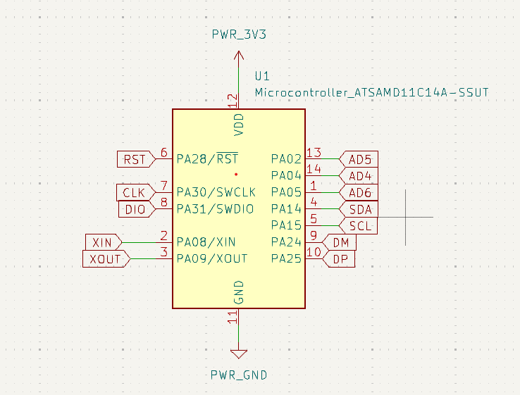
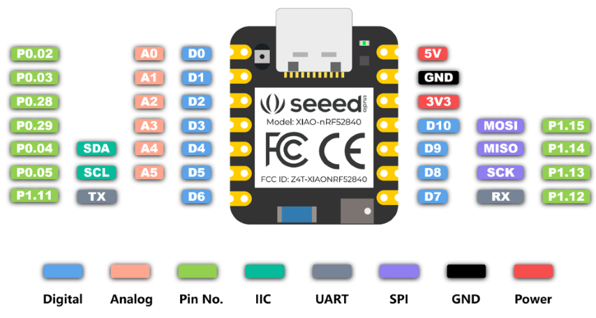
This week is a busy week for me with college obligations and few personal obligations. So I thought of choosing an output device which will be compatible with the board I had designed during electronics design. I already had taken out SDA, SCL, 5V and GND from SAMD11 which was perfect to connect LCD display with I2C module.
More details here in this documentation
.png)
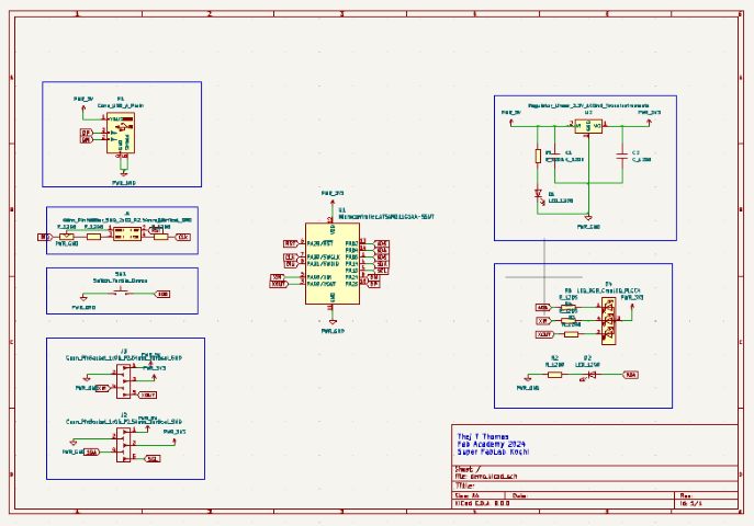
To understand the design, so I have made a voltage regulator circuit so as to get 3.3V for the microcontroller. I am using 1x04 header pin instead of 2x05 header pins for easy soldering. USB_A plain is actually a dummy for USB C type breakout board we had soldered in the week of electronics production. I have added an LED and a button, also 2 pin sockets. One socket is for I2C, I have taken SDA and SCL from the chip to the socket along with 5V, 3.3V and GND. Next socket, I took XIN, XOUT, remaining digital pin, GND and 5V onto the socket. I have labeled all the pins to the board.
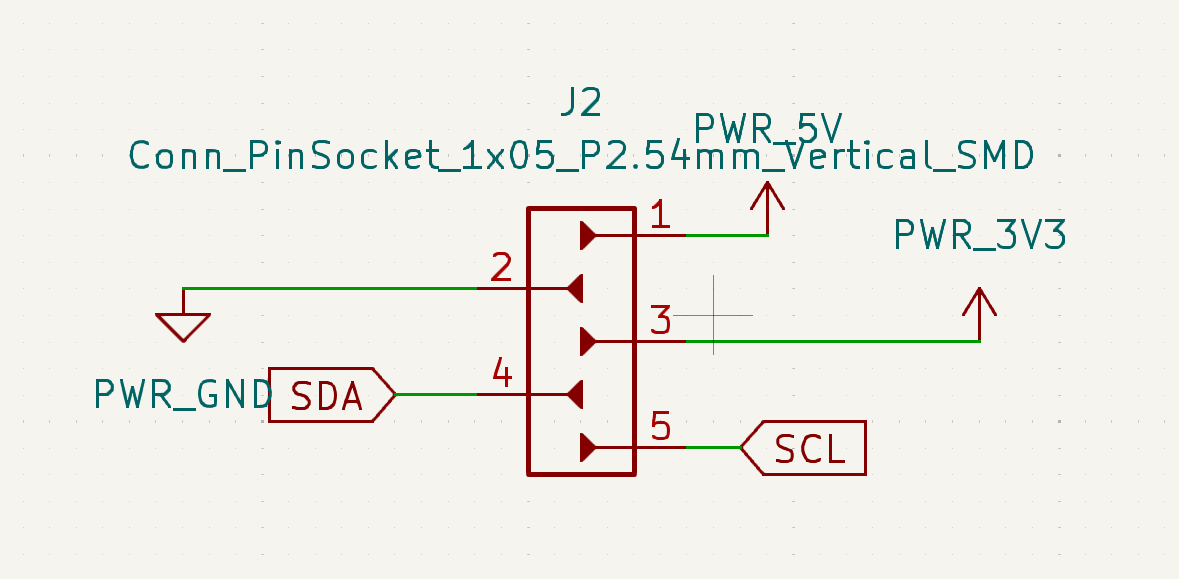
This is the SDA, SCL, 5V and GND I will be using for connecting LCD with I2C.
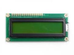
LCD Display
A 16x2 LCD (Liquid Crystal Display) is a common type of alphanumeric display that can show 16 characters per line and has 2 lines. When combined with an I2C (Inter-Integrated Circuit) interface, it becomes easier to connect to microcontrollers like Arduino or Raspberry Pi, as it reduces the number of wires needed for communication.
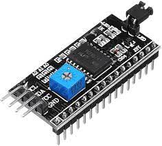
I2C, which stands for Inter-Integrated Circuit, is a synchronous, multi-master, multi-slave, packet-switched, single-ended, serial communication bus commonly used to connect low-speed peripherals to processors and microcontrollers. It was developed by Philips Semiconductor (now NXP Semiconductors) in the 1980s.
Key features of I2C include:
1. Two-wire Interface: I2C uses only two wires for communication: a serial data line (SDA) and a serial clock line (SCL). This makes it simple to implement and allows multiple devices to be connected to the same bus.
2. Master-Slave Communication: I2C operates in a master-slave configuration, where one device (the master) initiates communication and controls the bus, while one or more devices (the slaves) respond to commands from the master.
3. Addressing: Each slave device on the bus is assigned a unique 7-bit or 10-bit address, allowing the master to communicate with specific slaves.
4. Synchronous Communication: Communication on the I2C bus is synchronized to the clock signal generated by the master device.
5. Multi-Master Support: I2C supports multiple master devices on the same bus, allowing for more complex communication networks.
6. Packet-Based Communication: Data on the I2C bus is transferred in packets or frames, with each packet containing an address byte followed by one or more data bytes.
7. Low-Speed Communication: I2C is typically used for low-speed communication between devices, such as sensors, EEPROMs, real-time clocks, and other peripherals.
Overall, I2C is a popular choice for connecting peripherals in embedded systems due to its simplicity, flexibility, and widespread availability. It is commonly found in microcontrollers, development boards, and various electronic devices.
1. Display Size: 16 characters per line, 2 lines.
2. Communication Interface: I2C (Inter-Integrated Circuit). This allows for serial communication using only two wires (SDA and SCL), simplifying connections and reducing pin usage on microcontrollers.
3. Backlight: Many 16x2 LCDs come with a built-in LED backlight, usually blue or white, to illuminate the display for better visibility.
4. Controller: The 16x2 LCD with I2C typically uses a Hitachi HD44780 or compatible controller chip. This controller handles the low-level interface and display control, making it easier to interface with microcontrollers.
5. Voltage: Most 16x2 LCDs operate at 5V, but some models support 3.3V as well.
6. Character Set: The character set usually includes standard ASCII characters and some custom characters that can be defined by the user.
7. Contrast Adjustment: Some modules have a potentiometer for adjusting the contrast of the display, allowing you to optimize readability based on the viewing conditions.
8. Mounting Holes: Often, these modules come with mounting holes, making it easy to fix them onto a surface or enclosure.
9. Compatible Libraries: There are various libraries available for Arduino and other microcontrollers to interface with the 16x2 LCD using I2C, which simplifies programming and usage. When using a 16x2 LCD with I2C, you'll typically need to install a compatible library for your microcontroller platform. Then, you can use the provided functions to write text to the display, control the cursor, set the backlight, and so on, making it a convenient choice for many projects.
LCD Display Testing
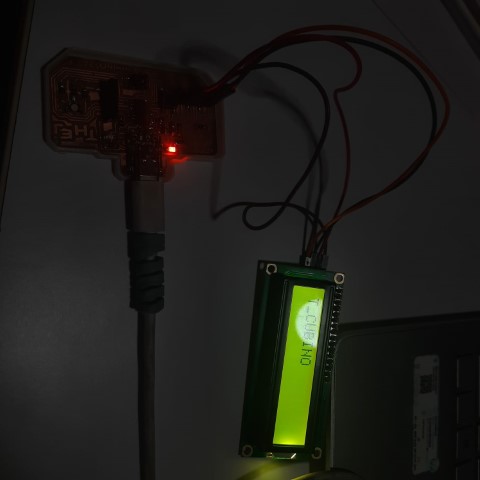
So referring to the schematic, I connected LCD to my board. And I tried to display my board name "T_CUBINO" on the screen.
| LCD with I2C | T_CUBINO Pin |
|---|---|
| VCC | PWR_5V |
| GND | PWR_GND |
| SDA | PA14 |
| SCL | PA15 |
    #include < Wire.h >
    #include < LiquidCrystal_I2C.h >

    // Set the LCD address to 0x27 for a 16 chars and 2 line display
    LiquidCrystal_I2C lcd(0x27, 16, 2);

    void setup() {
        // Initialize the LCD
        lcd.init();
        // Turn on the backlight
        lcd.backlight();
    }

    void loop() {
        // Clear the LCD screen
        lcd.clear();

        // Set the cursor to the first position
        lcd.setCursor(0, 0);

        // Print "hello" on the first line
        lcd.print("T_CUBINO");

        // Wait for a moment
        delay(1000);
    }
I had tried out a game in LCD display and Arduino UNO before FAB Academy. So since I had a button on my board I thought I will try to implement this game.
But the issue with my board is the flash size. So I had to find out how much of the game I could implement on the board. So I started from square one. I tried to display the character of a person.
    #include < Wire.h >
    #include < LiquidCrystal_I2C.h >

    // Define the custom character for a single pixel
    byte pixelChar[8] = {
        B01100,
        B01100,
        B00000,
        B01110,
        B11100,
        B01100,
        B11010,
        B10011
    };

    // Set up the LCD
    LiquidCrystal_I2C lcd(0x27, 16, 2);

    void setup() {
        // Initialize the LCD
        lcd.init();
        lcd.backlight();

        // Create the custom character
        lcd.createChar(0, pixelChar);

        // Set the cursor position and print the custom character
        lcd.setCursor(0, 0);
        lcd.write(byte(0)); // Display the custom character
    }

    void loop() {

    }
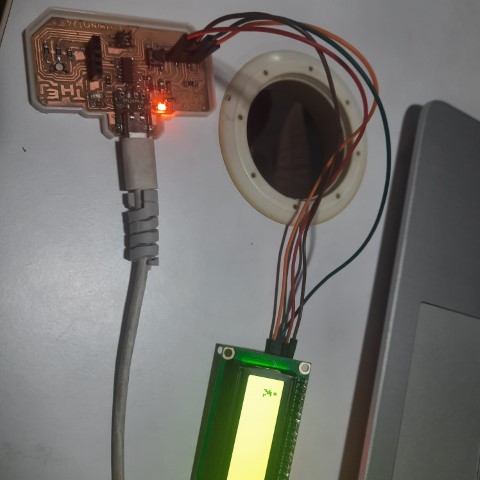
Now I thought of making the character walk
    #include < Wire.h >
    #include < LiquidCrystal_I2C.h >

    // Define custom characters for running poses
    byte runningChar1[8] = {
        B01100,
        B01100,
        B00000,
        B01110,
        B11100,
        B01100,
        B11010,
        B10011
    };

    byte runningChar2[8] = {
        B01100,
        B01100,
        B00000,
        B01100,
        B01100,
        B01100,
        B01100,
        B01110
    };

    // Set up the LCD
    LiquidCrystal_I2C lcd(0x27, 16, 2); // Change the address (0x27) if necessary

    void setup() {
        // Initialize the LCD
        lcd.init();
        lcd.backlight();
    }

    void loop() {
        // Display running character 1
        lcd.clear();
        lcd.createChar(0, runningChar1);
        lcd.setCursor(0, 0);
        lcd.write(byte(0));
        delay(500);

        // Display running character 2
        lcd.clear();
        lcd.createChar(0, runningChar2);
        lcd.setCursor(0, 0);
        lcd.write(byte(0));
        delay(500);
    }
Now I thought of making the character run
    #include < Wire.h >
    #include < LiquidCrystal_I2C.h >

    // Define custom characters for running poses
    byte runningChar1[8] = {
        B01100,
        B01100,
        B00000,
        B01110,
        B11100,
        B01100,
        B11010,
        B10011
    };

    byte runningChar2[8] = {
        B01100,
        B01100,
        B00000,
        B01100,
        B01100,
        B01100,
        B01100,
        B01110
    };

    // Set up the LCD
    LiquidCrystal_I2C lcd(0x27, 16, 2); // Change the address (0x27) if necessary

    int characterPosition = 0; // Initial position of the character

    void setup() {
        // Initialize the LCD
        lcd.init();
        lcd.backlight();
    }

    void loop() {
        // Display running character 1
        lcd.clear();
        displayCharacter(runningChar1);
        delay(200); // Adjust speed here

        // Display running character 2
        lcd.clear();
        displayCharacter(runningChar2);
        delay(200); // Adjust speed here
    }

    // Function to display the character at the current position
    void displayCharacter(byte character[]) {
        lcd.createChar(1, character);
        lcd.setCursor(characterPosition, 1);
        lcd.write(byte(1));
        characterPosition = (characterPosition + 1) % 16; // Wrap around if it reaches the end of the LCD
    }
With this the code size was already 94% of the allotted flash size of my board. Since I couldn't program LCD without the library due to the I2C module, I had to stop here. I tried to upload the code of the character jumping when I press button but it didn't upload due to huge size. I tried to optimise the code but I wasn't able to upload.
Buzzer
A buzzer is an electronic device that converts electrical signals into audible sound. Commonly used for alarms and notifications, it emits tones or beeps to indicate events or conditions. Buzzers come in various types, including piezoelectric and magnetic, each with specific operating voltages and sound output levels. They find applications in consumer electronics, industrial equipment, and safety systems. Controlled by digital signals from microcontrollers or other electronic devices, buzzers play a vital role in providing audible alerts and enhancing user experience. With their simplicity and reliability, buzzers serve as essential components in electronic systems worldwide.
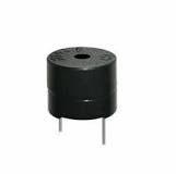
| Buzzer | T_CUBINO Pin |
|---|---|
| (-) | PWR_GND |
| (+) | PA14 |
Here's the code
    #define BUZZER_PIN 14 // Define the pin for the buzzer

    void setup() {
    pinMode(BUZZER_PIN, OUTPUT); // Set the buzzer pin as an output
    }

    void loop() {
    // Turn on the buzzer for 500 milliseconds (0.5 seconds)
    digitalWrite(BUZZER_PIN, HIGH);
    delay(500);

    // Turn off the buzzer for 500 milliseconds (0.5 seconds)
    digitalWrite(BUZZER_PIN, LOW);
    delay(500);
    }
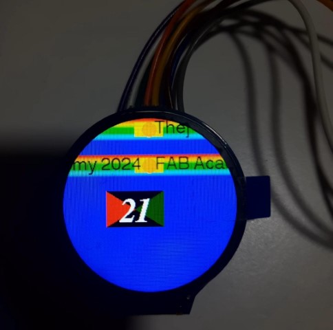
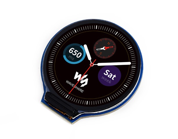
Watch Display (Project based)
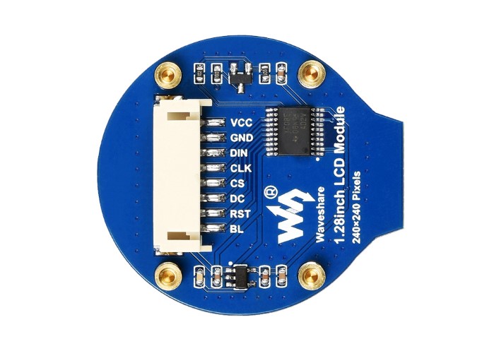
The 1.28" Round LCD Display Module features an embedded GC9A01 driver and utilizes the SPI bus for communication. It is a 240x240 Round RGB LCD Display featuring a four-wire SPI communication interface. By utilizing SPI, it efficiently utilizes GPIO ports and enables faster communication speeds. Similar in size to the 240x240 square LCD, it distinguishes itself with rounded edges. This LCD employs the GC9A01 driver, offering a resolution of 240RGB×240 dots.
| Pin | Description |
|---|---|
| VCC | Power (3.3V / 5V input) |
| GND | Ground |
| DIN | SPI data input |
| CLK | SPI clock input |
| CS | Chip selection, low active |
| DC | Data/Command selection (high for data, low for command) |
| RST | Reset, low active |
| BL | Backlight |
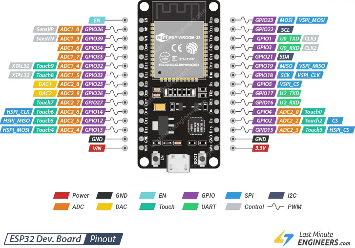
Interfacing with ESP 32
The ESP32 development board has 25 GPIO pins that can be assigned different functions by programming the appropriate registers. There are several kinds of GPIOs: digital-only, analog-enabled, capacitive-touch-enabled, etc. Analog-enabled GPIOs and Capacitive-touch-enabled GPIOs can be configured as digital GPIOs. Most of these digital GPIOs can be configured with internal pull-up or pull-down, or set to high impedance.
After refering the documentation of the display module, I thought of testing it out with ESP 32 Module.
So I referred this documentation and documentation for the testing.
Here's the pin connections
| ESP 32 Pin | Display Pin |
|---|---|
| 3V3 | VCC |
| GND | GND |
| G23 | DIN |
| G18 | CLK |
| G22 | CS |
| G16 | DC |
| G4 | RST |
| 3V3 | BL |
Now I need to set up the library.
I searched for “TFT_eSPI” and installed it.
I need to make a couple of modifications in order to get the library working, as it was meant for several types of displays and processors.
Here is what I did:
Using your File explorer, I navigated to Arduino Libraries folder, which is inside my Arduino folder in Documents.
Look for the TFT_eSPI folder and
Inside the folder, I found several files so I looked for the User_Setup.h file.
I opened the file using visual code studio and made the following edits:
Comment out the line defining the ILI9341 driver.
Uncomment the line defining the GC9A01 driver.
Comment out all the SPI definitions for the ILI9341.
For ESP 32, set MOSI to 23.
set SCLK to 18.
set CS to 22.
set DC to 16.
set RST to 4.
Then I saved the file.
.png)
A great demo code sample is the Animated_dial sketch, which is found inside the Sprites menu item from File>Examples>TFT_eSPI. This demonstration code will produce a “dial” indicator on the display, along with some simulated “data” (really just a random number generator). In order to run this sketch, I need to install another library. After installation, the code is uploaded and I get this output.
Next example is called Boing Ball Demo and it can be found in Example>TFT_eSPI> DMA Test>Boing Ball Demo
Next Sketch is this Scrolling Sprite Message which can be found in Example> TFT_eSPI> Sprite> ScrollingSprite 16 Bit. I made a few edits to the code to get this.
Seeed XIAO nRF52840 Sense
Since my final project is a swimming watch make a board with esp 32 module will make the watch size really big. So I found out a suitable board for my final project to interface with the display.
So I referred this documentation to understand the board and followed the steps of board installation. I implemented blink program and additionally, I implemented code to use the in-built sensor. Since that is an input device, I will document more details during the input week.
So I tried to implement the same steps I followed with the watch display and ESP 32 module. The example code was uploading successfully but the display wasn't showing anything.
I'm still trying to figure it out.
Update
So it turns out, I need a different library to configure display with this board. However I found a display i.e. Seeed Studio 1.28-inch Round Touch Display for XIAO which work well with this board. So I'm ordering it.
Group Assignment
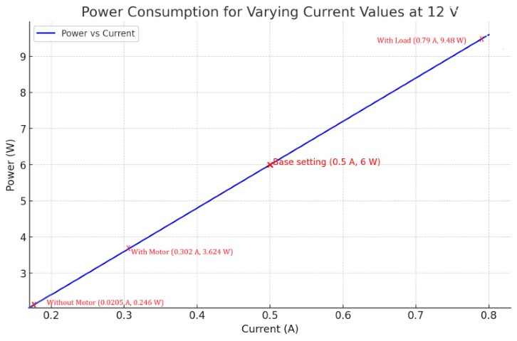
In this experiment, we measured the power consumption of a Stepper motor under different conditions by recording the current and voltage values and calculating the power using 𝑃=𝑉×𝐼. The results show a linear increase in power consumption with increasing current, which is visually represented in the graph. By understanding the power consumption characteristics of the Stepper motor, we can better optimize its performance and ensure efficient energy usage in practical applications.
Click here: Measure the power consumption of an output device