Input Devices
Individual Assignment
Measure something: add a sensor to a microcontroller board that you have designed and read it
Group Assignment
Probe an input device's analog levels and digital signals
Table of Contents
Group Assignment
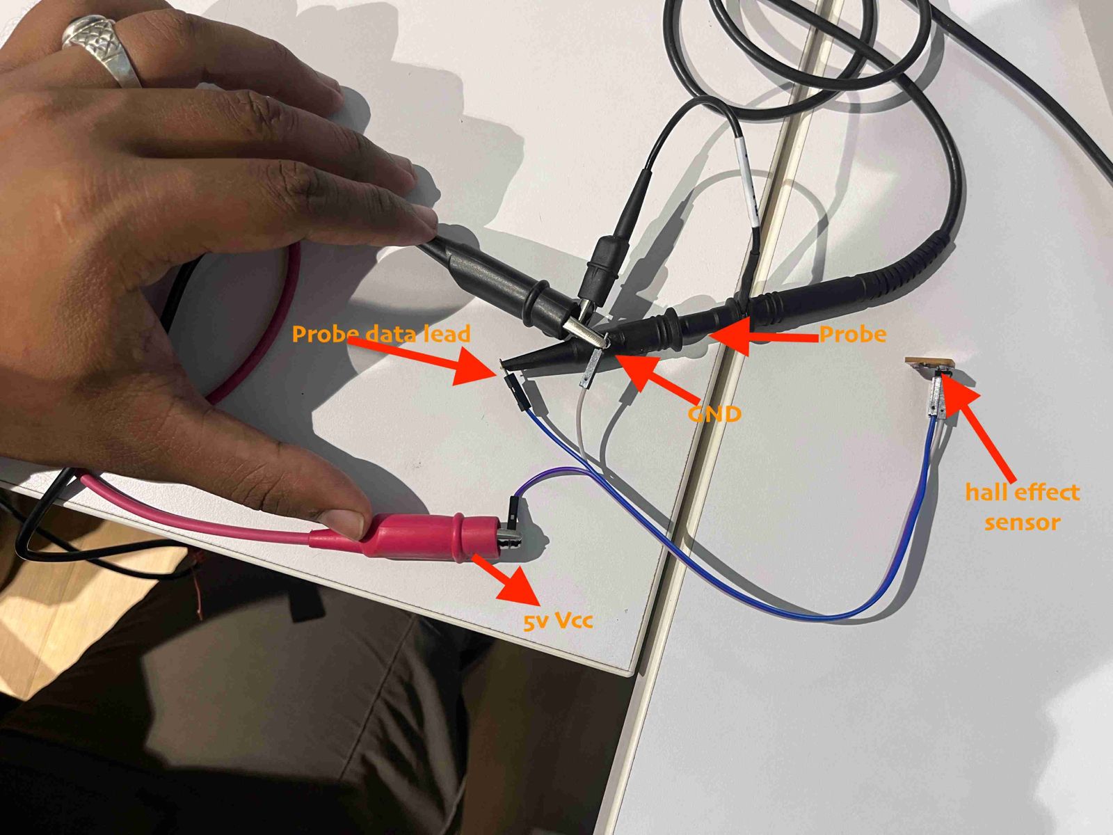
Click here: Probe an input device's analog levels and digital signals
Input Devices
After the stressful machine week, I just wanted to take a long break. I was feeling very lazy to start the next assignment. But when I saw the flexible capacitive sensor, I was very intrigued and wanted to test the same. However, when I finally got the motivation to try out something cool, I started feeling under the weather. I was getting sick and getting better and then again getting sick and getting better. This was going on and off. I took leaves and was left with one day to complete the assignment. So let's see how much I did:
ADXL345
ADXL345 is a Breakout board for the Analog Device's ADXL345 triple axis accelerometer. The module is populated with MOSFET based Voltage level conversion circuitry to enable you to interface different type of microcontrollers (3V3 & 5V). Apart from the above all, necessary components like decoupling capacitors ,filter capacitors ,pull up resistors and LED are also populated on board.
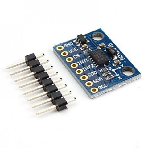
It is ideal for motion and acceleration sensing applications.It is a low-power, 3-axis MEMS accelerometer modules with both I2C and SPI interfaces.
The ADXL345 features 4 sensitivity ranges from +/- 2G to +/- 16G. And it supports output data rates ranging from 10Hz to 3200Hz such as the Arduino.
Key features include:
1. Digital Output: SPI / I2C
2. Low Power Consumption
3. Compact Accelemotor / inclinometer
4. 5V/3.3V input support.
5. PCB Board Size: 28mm x 14 mm
ADXL345 Testing
So referring to the schematic of my board week 8 , I connected ADXL435 to my board.
| ADXL345 | T_CUBINO Pin |
|---|---|
| VCC | PWR_5V |
| GND | PWR_GND |
| SDA | PA14 |
| SCL | PA15 |
I ran the example code but I had forgotten the flashsize of SAMD11C, so it showed me error! Therefore I referred documentation of previous FAB students. The code was written for MPU6050 so I had to change it for ADXL345.
    #include < Wire.h >

        const int ADXL_addr = 0x53; // I2C address of the ADXL345 accelerometer

        void setup() {
            Serial.begin(9600);
            Wire.begin();

            // Configure ADXL345
            writeTo(ADXL_addr, 0x2D, 8); // Power Control Register - Set to measure mode
        }

        void loop() {
            static unsigned long lastPrintTime = 0;

            if (millis() - lastPrintTime >= 5000) { // Print every 5 seconds
            // Read accelerometer data
            int16_t accX = read16BitsFrom(ADXL_addr, 0x32);
            int16_t accY = read16BitsFrom(ADXL_addr, 0x34);
            int16_t accZ = read16BitsFrom(ADXL_addr, 0x36);

            // Print accelerometer data
            Serial.print("AcX = ");
            Serial.print(accX);
            Serial.print(" | AcY = ");
            Serial.print(accY);
            Serial.print(" | AcZ = ");
            Serial.println(accZ);

            lastPrintTime = millis();
            }
        }

        void writeTo(int address, byte reg, byte val) {
            Wire.beginTransmission(address);
            Wire.write(reg);
            Wire.write(val);
            Wire.endTransmission();
        }

        int16_t read16BitsFrom(int address, byte reg) {
            Wire.beginTransmission(address);
            Wire.write(reg);
            Wire.endTransmission(false);
            Wire.requestFrom(address, 2, true);
            return (Wire.read() | (Wire.read() << 8));
        }

    }
These were the values getting read.
.png)
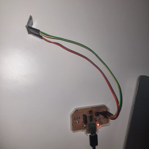
Seeed XIAO nRF52840 Sense
Since my final project is a swimming watch make a board with esp 32 module will make the watch size really big. So I found out a suitable board for my final project to interface with the display.
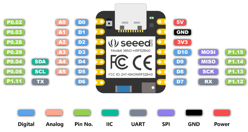
So I referred this documentation to understand the board and followed the steps of board installation. I implemented blink program and additionally, I tried to test the inbuilt sensor which is an accelerometer.
So I referred this documentation and used the code there to test the sensor. That documentation is about using tinyml to sense the human acitivity by one of the instructors Salman Farris.
  // XIAO BLE Sense LSM6DS3 Data  Forwarder

  #include "LSM6DS3.h"
  #include "Wire.h"

  //Create a instance of class LSM6DS3
  LSM6DS3 myIMU(I2C_MODE, 0x6A);  //I2C device address 0x6A

  #define CONVERT_G_TO_MS2 9.80665f
  #define FREQUENCY_HZ 50
  #define INTERVAL_MS (1000 / (FREQUENCY_HZ + 1))

  static unsigned long last_interval_ms = 0;


  void setup() {
    Serial.begin(115200);
    while (!Serial)
      ;

    if (myIMU.begin() != 0) {
      Serial.println("Device error");
    } else {
      Serial.println("Device OK!");
    }
  }


  void loop() {
    if (millis() > last_interval_ms + INTERVAL_MS) {
      last_interval_ms = millis();
      Serial.print(myIMU.readFloatAccelX() * CONVERT_G_TO_MS2, 4);
      Serial.print('\t');
      Serial.print(myIMU.readFloatAccelY() * CONVERT_G_TO_MS2, 4);
      Serial.print('\t');
      Serial.println(myIMU.readFloatAccelZ() * CONVERT_G_TO_MS2, 4);
    }
  }
So I tried to keep the microcontroller with my watch and tried to immitate the swimming movements with my hands. The values are getting displayed accordingly.
So for my final project, I'm thinking of using tinyml to train the movements of somersault to count the number of laps. I am a little bit familiarised with tinyml since I had attended a workshop about it by one of the instructor Salman Farris before Fab Academy. So the workshop was about using tinyml to sense the movements of the microcontroller. A similar implementation is available in this documentation about using tinyml for sensing human activity.
So here is the library generated during the workshop>
Magic Wand
Next, I uploaded this code to the board
  /* Includes ---------------------------------------------------------------- */
  #include < Xiao-nRF-MagicWand-LightControl_inferencing.h > //replace the library name with yours
  #include "LSM6DS3.h"

  /* Constant defines -------------------------------------------------------- */
  #define CONVERT_G_TO_MS2    9.80665f
  #define MAX_ACCEPTED_RANGE  2.0f        // starting 03/2022, models are generated setting range to +-2, but this example use Arudino library which set range to +-4g. If you are using an older model, ignore this value and use 4.0f instead
  #define INTERVAL_MS (1000 / (FREQUENCY_HZ + 1))
  static unsigned long last_interval_ms = 0;

  LSM6DS3 myIMU(I2C_MODE, 0x6A);  //I2C device address 0x6A

  static bool debug_nn = false; // Set this to true to see e.g. features generated from the raw signal

  /**
  * @brief      Arduino setup function
  */
  void setup()
  {
      // put your setup code here, to run once:
      Serial.begin(115200);
      // comment out the below line to cancel the wait for USB connection (needed for native USB)
      while (!Serial);
      Serial.println("Edge Impulse Inferencing Demo");

      if (!myIMU.begin()) {
          ei_printf("Failed to initialize IMU!\r\n");
      }
      else {
          ei_printf("IMU initialized\r\n");
      }

      if (EI_CLASSIFIER_RAW_SAMPLES_PER_FRAME != 3) {
          ei_printf("ERR: EI_CLASSIFIER_RAW_SAMPLES_PER_FRAME should be equal to 3 (the 3 sensor axes)\n");
          return;
      }
  }

  /**
  * @brief Return the sign of the number
  *
  * @param number
  * @return int 1 if positive (or 0) -1 if negative
  */
  float ei_get_sign(float number) {
      return (number >= 0.0) ? 1.0 : -1.0;
  }

  /**
  * @brief      Get data and run inferencing
  *
  * @param[in]  debug  Get debug info if true
  */
  void loop()
  {
      //ei_printf("\nStarting inferencing in 2 seconds...\n");

      delay(2000);

      //ei_printf("Sampling...\n");

      // Allocate a buffer here for the values we'll read from the IMU
      float buffer[EI_CLASSIFIER_DSP_INPUT_FRAME_SIZE] = { 0 };

      for (size_t ix = 0; ix < EI_CLASSIFIER_DSP_INPUT_FRAME_SIZE; ix += 3) {
          // Determine the next tick (and then sleep later)
          uint64_t next_tick = micros() + (EI_CLASSIFIER_INTERVAL_MS * 1000);

          //IMU.readAcceleration(buffer[ix], buffer[ix + 1], buffer[ix + 2]);

          buffer[ix+0] = myIMU.readFloatAccelX();
          buffer[ix+1] = myIMU.readFloatAccelY();
          buffer[ix+2] = myIMU.readFloatAccelZ();


          for (int i = 0; i < 3; i++) {
              if (fabs(buffer[ix + i]) > MAX_ACCEPTED_RANGE) {
                  buffer[ix + i] = ei_get_sign(buffer[ix + i]) * MAX_ACCEPTED_RANGE;
              }
          }

          buffer[ix + 0] *= CONVERT_G_TO_MS2;
          buffer[ix + 1] *= CONVERT_G_TO_MS2;
          buffer[ix + 2] *= CONVERT_G_TO_MS2;

          delayMicroseconds(next_tick - micros());
      }

      // Turn the raw buffer in a signal which we can the classify
      signal_t signal;
      int err = numpy::signal_from_buffer(buffer, EI_CLASSIFIER_DSP_INPUT_FRAME_SIZE, &signal);
      if (err != 0) {
          ei_printf("Failed to create signal from buffer (%d)\n", err);
          return;
      }

      // Run the classifier
      ei_impulse_result_t result = { 0 };

      err = run_classifier(&signal, &result, debug_nn);
      if (err != EI_IMPULSE_OK) {
          ei_printf("ERR: Failed to run classifier (%d)\n", err);
          return;
      }

      // print the predictions
    // ei_printf("Predictions ");
    // ei_printf("(DSP: %d ms., Classification: %d ms., Anomaly: %d ms.)",
    // result.timing.dsp, result.timing.classification, result.timing.anomaly);
      //ei_printf("\n");
      for (size_t ix = 0; ix < EI_CLASSIFIER_LABEL_COUNT; ix++) {
    // ei_printf("    %s: %.5f\n", result.classification[ix].label, result.classification[ix].value);
      if (result.classification[ix].value > .5) {
          ei_printf("%s \n", result.classification[ix]);
      }
      }

      //  if (result.classification[ix].value > .5) {
      //     ei_printf("    %s: %.5f\n", result.classification[ix].label, result.classification[ix].value);
      // }
      // }


  #if EI_CLASSIFIER_HAS_ANOMALY == 1
      ei_printf("anomaly score: %.3f\n", result.anomaly);
  #endif
  }

  #if !defined(EI_CLASSIFIER_SENSOR) || EI_CLASSIFIER_SENSOR != EI_CLASSIFIER_SENSOR_ACCELEROMETER
  #error "Invalid model for current sensor"
  #endif
So this code will sense the motion of the microcontroller and identify if it is circle, idle or swish.
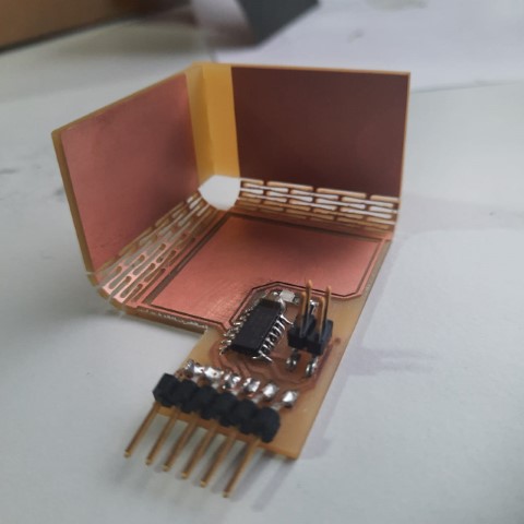
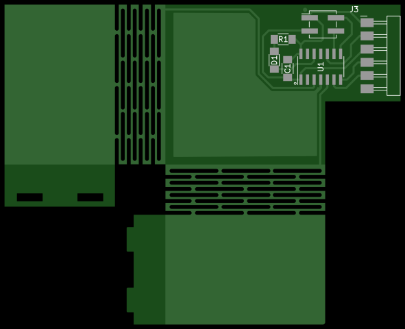
Flexible Capacitive Sensor
SAMD11C Flexible Capacitor looked really interesting and fun so I thought of trying it out but with ATTINY1614. Since ATTINY1614 had QTouch embedded in it, I could use it as well.
.jpg)
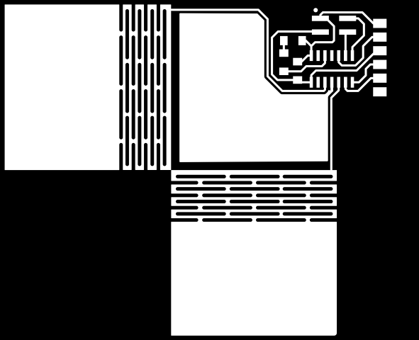
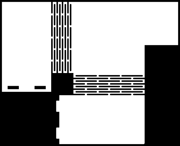
Here is the redesigned circuit using Attiny1614
.png)
.png)
Next, I converted Gerber to PNG using this website.
Next, I gave the file for milling.
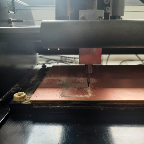
After the milling and cutting was done, I realised the flexures weren't cut. Turns out with 1/32 bit, the flexure cut weren't being calculated.
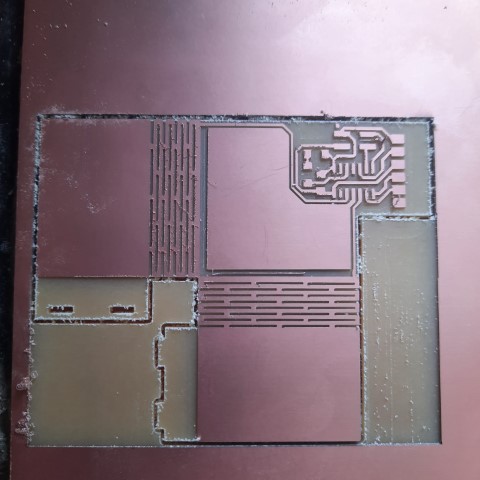
So my instructor changed the settings of the bit and did the cutting of the flexures again.
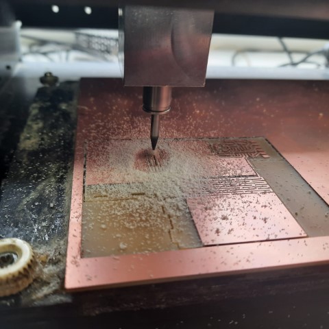
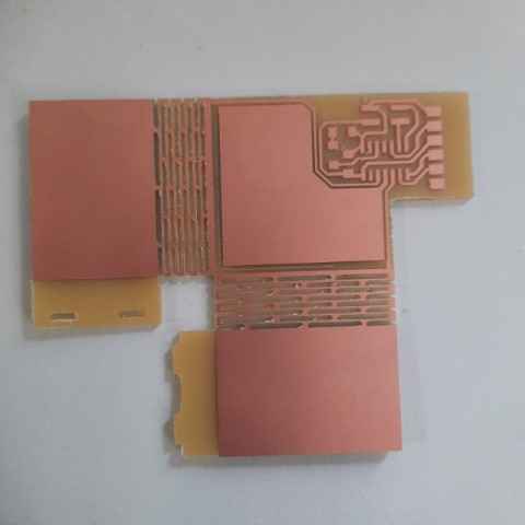
The flexures were done successfully!
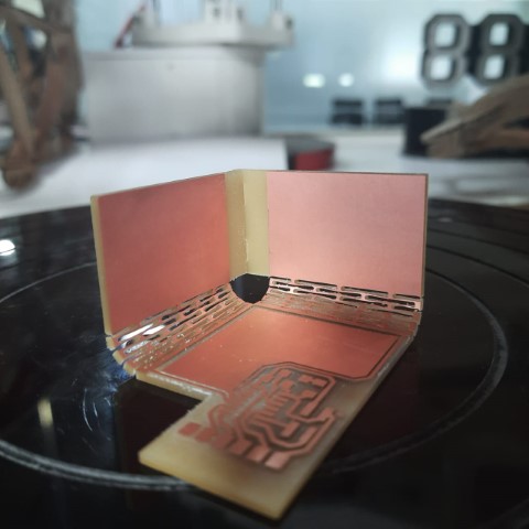
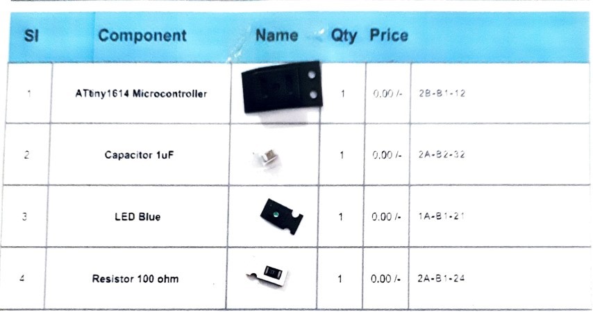
Next, I acquired the components. There are 2 things missing in the list: 2x2 header pin and and 6pos header pins
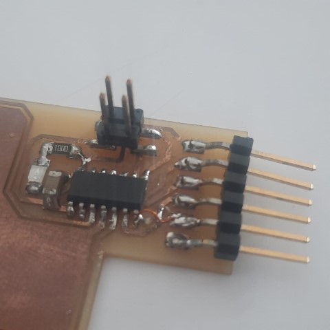
I finished soldering!
Next, I'll start to program the board and test if it works.
Since I am using Quentorres board as programmer, there's a few steps to be followed like I did in week 8. Then for Attiny1614, there's these additional steps:
.png)
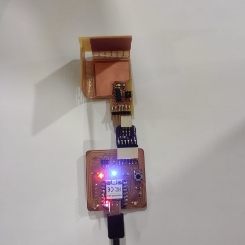
I tried the blink program and it works!
I referred the documentation but the library used in the code wasn't optimsed for Attiny1614, so I asked ChatGPT for code without library. But nothing was getting displayed on serial monitor. After troubleshooting, it was found that there was hardware errors. So I had inverted RX and TX pins of the header pins to connect it to the chip but I didn't have to do that since the pins were already inverted. But incase of socket, I'll have to invert it.
.png)
So I used jumper wires and connected it correctly and checked with a simple code to display hello world. It worked! However I tried to get the capacitance values to be displayed but it wasn't still working with the jumper wires. I'm working on it.
Upon countless hours of researching I found that I could create a Qtouch library myself from ATMEL start. From this page, go to create new project.
.png)
Next, choose the board, I'm using ATTINY1614 and under drivers choose PTC.
.png)
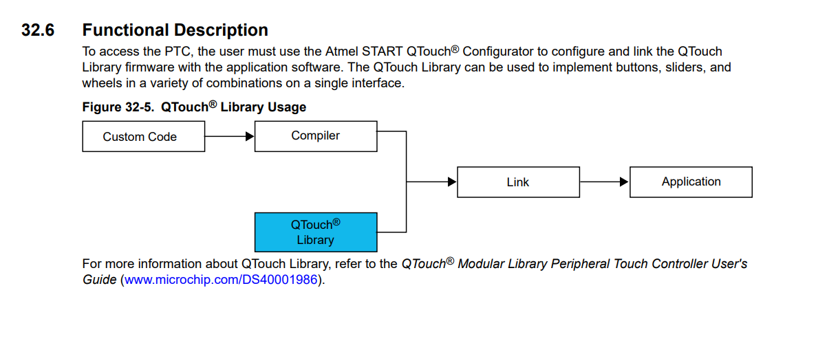
This window appears and now click QTouch and then Open QTouch Configurator.
.png)
A warning shows, click yes.
.png)
Under sensors, choose buttons as 3. Next, under pins, reset the pin numbers first and then reassign the pins for the board based on schematic.
.png)
After that I exported the project by downloading pack.
.png)
Now import that into Atmel Studio. You can download Atmel Studio here.
.png)
.png)
In the main.c code add a line to call the touch_example function. This function can be found in the example>src folder.
.png)
However I wasn't able to proceed furthur. I think I'm stopping with the QTouch here due to library issues. Here are some of my references: 1 2 3 4
Since I wasn't able to succeed with QTouch, I thought I'll try step response. Since the board was already milled, I had to explicitly add 1Mohms between the pads. Also I faced another problem, the flexures broke while I was disassembling the board no problem, I soldered the joints and fixed it as well.
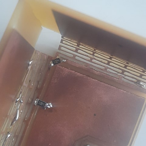
I refered Neil's code for Step Response but since it was for Attiny1624, I modified the code for Attiny1614 thanks to ChatGPT.
    //
    // hello.txrx.t1614.ino
    //
    // ATtiny1614 step response
    //

    //
    // This work may be reproduced, modified, distributed,
    // performed, and displayed for any purpose, but must
    // acknowledge this project. Copyright is retained and
    // must be preserved. The work is provided as is; no
    // warranty is provided, and users accept all liability.
    //

    #define rxpin1 PIN_PA5 // receive pin (PA5 on ATtiny1614)
    #define rxpin2 PIN_PA6 // receive pin (PA6 on ATtiny1614)
    #define txpin PIN_PA7 // transmit pin (PA7 on ATtiny1614)
    #define settle 100 // settle time
    #define samples 100 // number of samples to accumulate

    void setup() {
       Serial.begin(115200); // start serial
       pinMode(txpin, OUTPUT); // set transmit pin to output
       pinMode(rxpin1, INPUT); // set receive pin1 to input
       pinMode(rxpin2, INPUT); // set receive pin2 to input
    }

    void loop() {
       int32_t up, down;
       up = down = 0;
       noInterrupts(); // disable interrupts while measuring
       for (int i = 0; i < samples; ++i) {
          digitalWrite(txpin, HIGH); // charge up
          up += analogRead(rxpin1); // read from rxpin1
          delayMicroseconds(settle); // settle
          digitalWrite(txpin, LOW); // charge down
          down += analogRead(rxpin1); // read from rxpin1
          delayMicroseconds(settle); // settle
       }
       interrupts(); // enable interrupts after measuring
       Serial.println(up - down); // send difference
       Serial.flush(); // finish communicating before measuring
    }
.png)
The values based upon the pad I touch.
I tried to display which pad what was touched based upon the values
    //
    // hello.txrx.t1614.ino
    //
    // ATtiny1614 step response
    //

    //
    // This work may be reproduced, modified, distributed,
    // performed, and displayed for any purpose, but must
    // acknowledge this project. Copyright is retained and
    // must be preserved. The work is provided as is; no
    // warranty is provided, and users accept all liability.
    //

    #define rxpin1 PIN_PA5 // receive pin (PA5 on ATtiny1614)
    #define rxpin2 PIN_PA6 // receive pin (PA6 on ATtiny1614)
    #define txpin PIN_PA7 // transmit pin (PA7 on ATtiny1614)
    #define settle 100 // settle time
    #define samples 100 // number of samples to accumulate

    void setup() {
       Serial.begin(115200); // start serial
       pinMode(txpin, OUTPUT); // set transmit pin to output
       pinMode(rxpin1, INPUT); // set receive pin1 to input
       pinMode(rxpin2, INPUT); // set receive pin2 to input
    }

    void loop() {
       int32_t up, down;
       up = down = 0;
       noInterrupts(); // disable interrupts while measuring
       for (int i = 0; i < samples; ++i) {
          digitalWrite(txpin, HIGH); // charge up
          up += analogRead(rxpin1); // read from rxpin1
          delayMicroseconds(settle); // settle
          digitalWrite(txpin, LOW); // charge down
          down += analogRead(rxpin1); // read from rxpin1
          delayMicroseconds(settle); // settle
       }
       interrupts(); // enable interrupts after measuring

       int32_t difference = up - down;

       // Display messages based on the measured values
       if (difference >= -20000 && difference <= -18000) {
          Serial.print("Bottom pad touched: ");
          Serial.println(difference);
       } else if (difference >= -9000 && difference <= -5000) {
          Serial.print("Left pad touched: ");
          Serial.println(difference);
       } else if (difference < -20000) {
          Serial.print("Right pad touched: ");
          Serial.println(difference);
       } else if (difference >= -12000 && difference <= -8500) {
          Serial.print("Untouched: ");
          Serial.println(difference);
       }

       Serial.flush(); // finish communicating before measuring
    }
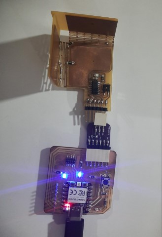
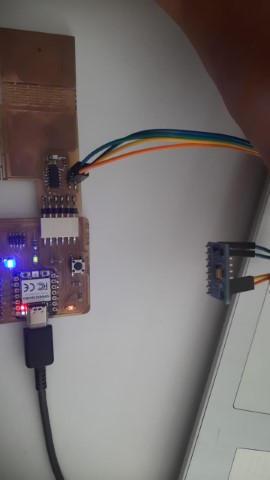
I really wanted to work and debug the issues I faced with Qtouch but I also had to finish the assignment. So I am adding ADXL345 accelerometer to this board since I had taken header pins of SDA, SCL. I had already mentioned about ADXL345 above.
| ADXL345 | Board Pin |
|---|---|
| VCC | PWR_5V (Header Pin 1) |
| GND | PWR_GND (Header Pin 3) |
| SDA | SDA (Header Pin 2) |
| SCL | SCL (Header Pin 4) |
    #include < Wire.h >  // Include the Wire library for I2C communication
    #include < Adafruit_Sensor.h > // Include Adafruit Sensor library
    #include < Adafruit_ADXL345_U.h > // Include Adafruit ADXL345 library

            // Assign a unique ID to this sensor
            Adafruit_ADXL345_Unified accel = Adafruit_ADXL345_Unified(12345);

            // Function to display sensor details
            void displaySensorDetails(void) {
                sensor_t sensor;
                accel.getSensor(&sensor);
                Serial.println("------------------------------------");
                Serial.print("Sensor:       "); Serial.println(sensor.name);
                Serial.print("Driver Ver:   "); Serial.println(sensor.version);
                Serial.print("Unique ID:    "); Serial.println(sensor.sensor_id);
                Serial.print("Max Value:    "); Serial.print(sensor.max_value); Serial.println(" m/s^2");
                Serial.print("Min Value:    "); Serial.print(sensor.min_value); Serial.println(" m/s^2");
                Serial.print("Resolution:   "); Serial.print(sensor.resolution); Serial.println(" m/s^2");
                Serial.println("------------------------------------");
                Serial.println("");
                delay(500);
            }

            // Function to display the data rate of the accelerometer
            void displayDataRate(void) {
                Serial.print("Data Rate:    ");

                // Print the current data rate
                switch(accel.getDataRate()) {
                case ADXL345_DATARATE_3200_HZ:
                    Serial.print("3200 ");
                    break;
                case ADXL345_DATARATE_1600_HZ:
                    Serial.print("1600 ");
                    break;
                case ADXL345_DATARATE_800_HZ:
                    Serial.print("800 ");
                    break;
                case ADXL345_DATARATE_400_HZ:
                    Serial.print("400 ");
                    break;
                case ADXL345_DATARATE_200_HZ:
                    Serial.print("200 ");
                    break;
                case ADXL345_DATARATE_100_HZ:
                    Serial.print("100 ");
                    break;
                case ADXL345_DATARATE_50_HZ:
                    Serial.print("50 ");
                    break;
                case ADXL345_DATARATE_25_HZ:
                    Serial.print("25 ");
                    break;
                case ADXL345_DATARATE_12_5_HZ:
                    Serial.print("12.5 ");
                    break;
                case ADXL345_DATARATE_6_25HZ:
                    Serial.print("6.25 ");
                    break;
                case ADXL345_DATARATE_3_13_HZ:
                    Serial.print("3.13 ");
                    break;
                case ADXL345_DATARATE_1_56_HZ:
                    Serial.print("1.56 ");
                    break;
                case ADXL345_DATARATE_0_78_HZ:
                    Serial.print("0.78 ");
                    break;
                case ADXL345_DATARATE_0_39_HZ:
                    Serial.print("0.39 ");
                    break;
                case ADXL345_DATARATE_0_20_HZ:
                    Serial.print("0.20 ");
                    break;
                case ADXL345_DATARATE_0_10_HZ:
                    Serial.print("0.10 ");
                    break;
                default:
                    Serial.print("???? ");
                    break;
                }
                Serial.println(" Hz");
            }

            // Function to display the range of the accelerometer
            void displayRange(void) {
                Serial.print("Range:         +/- ");

                // Print the current range
                switch(accel.getRange()) {
                case ADXL345_RANGE_16_G:
                    Serial.print("16 ");
                    break;
                case ADXL345_RANGE_8_G:
                    Serial.print("8 ");
                    break;
                case ADXL345_RANGE_4_G:
                    Serial.print("4 ");
                    break;
                case ADXL345_RANGE_2_G:
                    Serial.print("2 ");
                    break;
                default:
                    Serial.print("?? ");
                    break;
                }
                Serial.println(" g");
            }

            // Setup function runs once when the microcontroller starts
            void setup(void) {
                #ifndef ESP8266
                while (!Serial); // Wait for serial port to connect (for Leonardo/Micro/Zero)
                #endif
                Serial.begin(9600); // Initialize serial communication at 9600 baud rate
                Serial.println("Accelerometer Test"); Serial.println("");

                // Initialize the sensor
                if(!accel.begin()) {
                // If there's a problem detecting the ADXL345, check the connections
                Serial.println("Ooops, no ADXL345 detected ... Check your wiring!");
                while(1);
                }

                // Set the range to whatever is appropriate for your project
                accel.setRange(ADXL345_RANGE_16_G);
                // accel.setRange(ADXL345_RANGE_8_G);
                // accel.setRange(ADXL345_RANGE_4_G);
                // accel.setRange(ADXL345_RANGE_2_G);

                // Display some basic information on this sensor
                displaySensorDetails();

                // Display additional settings (outside the scope of sensor_t)
                displayDataRate();
                displayRange();
                Serial.println("");
            }

            // Loop function runs continuously after setup
            void loop(void) {
                // Get a new sensor event
                sensors_event_t event;
                accel.getEvent(&event);

                // Display the results (acceleration is measured in m/s^2)
                Serial.print("X: "); Serial.print(event.acceleration.x); Serial.print("  ");
                Serial.print("Y: "); Serial.print(event.acceleration.y); Serial.print("  ");
                Serial.print("Z: "); Serial.print(event.acceleration.z); Serial.print("  ");Serial.println("m/s^2 ");
                delay(500); // Wait for 500 milliseconds before the next loop iteration
            }
.png)
Files
Step Response for ATtiny1614
ADXL345 code for ATTINY1614
Touch code for ATTINY1614
PNG Files
PCB Files