My Final Project
An Experimental Setup for PhD Research
Description
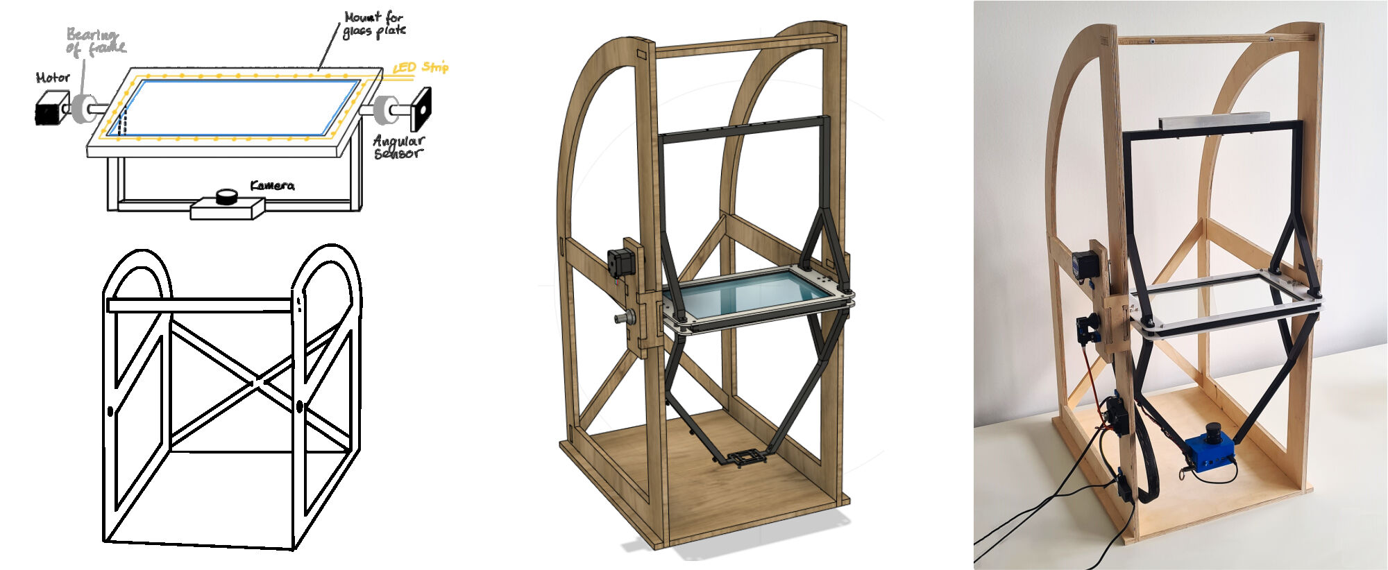
I am a researcher currently starting my PhD about soft robotics bio-inspired by soft-bodied animals. To make the most of my limited time, I want to use my final project for my PhD, i.e. to produce an experimental setup that allows me to visualize the contact of a small animal with its surroundings. More specifically, I want to make the contact area between the animal and a glass plate visible by "frustrated total internal reflection" (FTIR) under different environmental conditions, such as a normal horizontal plate, a wall or even an overhang environment to also assess its attachment performance.
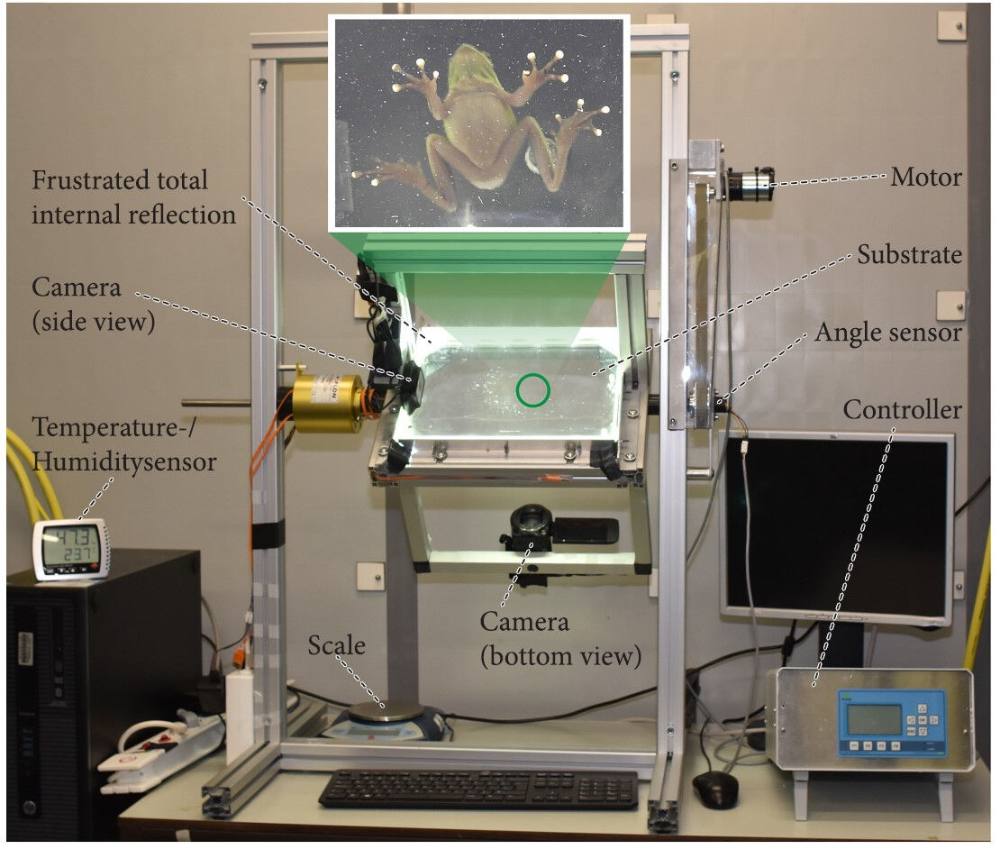
This experimental setup already exists, made by a research group at the University Wageningen in the Netherlands. However, setups like these are self-made and cannot be bought off-the-shelf. Therefore, I have to build one myself during FabAcademy 2024.
From: Langowski, J. K. A., Rummenie, A., Pieters, R. P. M., Kovalev, A., Gorb, S. N., & van Leeuwen, J. L. (2019). Estimating the maximum attachment performance of tree frogs on rough substrates. Bioinspiration & Biomimetics, 14(2), 025001. https://doi.org/10.1088/1748-3190/aafc37
Project Management
Already in the first week of FabAcademy, project management is an essential task. This includes defining requirements, sketching the idea, time management, creating a bill of materials and a fabrication plan.
Requirements
I started project management with formulating some demands and wishes what the final project should implement.
Demands
- An LED strip must be placed around the glass plate.
- The glass plate must be connected to a rotating shaft able of rotating 90°.
- A camera must be able to record the surface of the glass plate from below.
- The camera must be able to follow the rotations of the shaft.
- The shaft must be suspended by a frame.
- The rotation is controlled by a motor.
- An angle sensor is used to measure the angle
- A GUI is used as an interface via USB to the microcontroller.
- The microcontroller has a housing.
Wishes (optional)
- The camera is connected and controlled via a microcontroller.
- The rotation is controlled by the angle measurements.
- For a high contrast, the setup should be partially enclosed by a shading box.
- The rotation is extended to 180°.
- All wires and other electrical components are integrated and not visible.
- It can be placed on a table, i.e. the dimensions are less than 120cm x 60cm x 60cm (h x w x d).
Sketching the Idea
Below, you can see the sketches of the experimental setup how I imagined it. You can see, it does not really differ from the image shown in the description. However, sketching emphasizes concepts and important aspects and is therefore an important task.
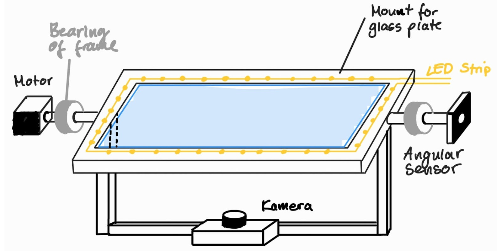
Sketch of Components Suspended by the Frame
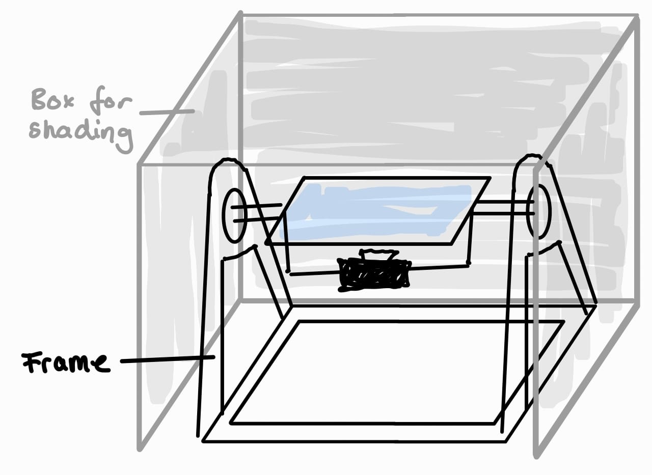
Sketch of Frame and Enclosure
Laster, as you an see here, I neglected the shading box and instead focussed on the frame which can also be enclosed by attaching sheets of material on its sides.
Time Management
In addition to the demands and sketching the idea, time management is an essential task. I addressed this also in the documentation for the first week. However, in contrast to it, I will keep the Gantt Chart below updated on this page. You can see in which week I contributed to a task as these weeks are marked with an "X". The weeks in which I plan to accomplish them are marked in orange and buffer time is marked with yellow.

Gantt Chart (Last Edit: 21st of June 2024)
Bill of Materials & Fabrication Plan
The bill of materials as well as a fabrication plan was part of the assignment on applications & implications. For this assignment, I divided the bill of materials into the parts I will be making, components I will be buying and the electrical parts. For the former, I will be using the fabrication processes of 3D printing, CNC milling, PCB milling and lasercutting with PLA, wooden multiplex boards, a FR4 copper sheet and 3 mm POM sheets, respectively. The expenses amount to about 81.25 €.
The components cost in total 281.04 €. The main parts of the expenses are caused by the camera which consists of a Raspberry Pi board, a camera module and a lens, as well as the glass plate and the LED strip.
Almost all of the electrical components were available in the FabLab which makes it hard to state the costs for them. However, I estimated them to be about 15 €.
Please refer to the according assignment for the details on the bill of materials and the fabrication plan. There, I have shown, which parts are needed for my final project, bought or made, the source of the part/material, the individual costs, quantities and if applicable the fabrication process.
Mechanical Components
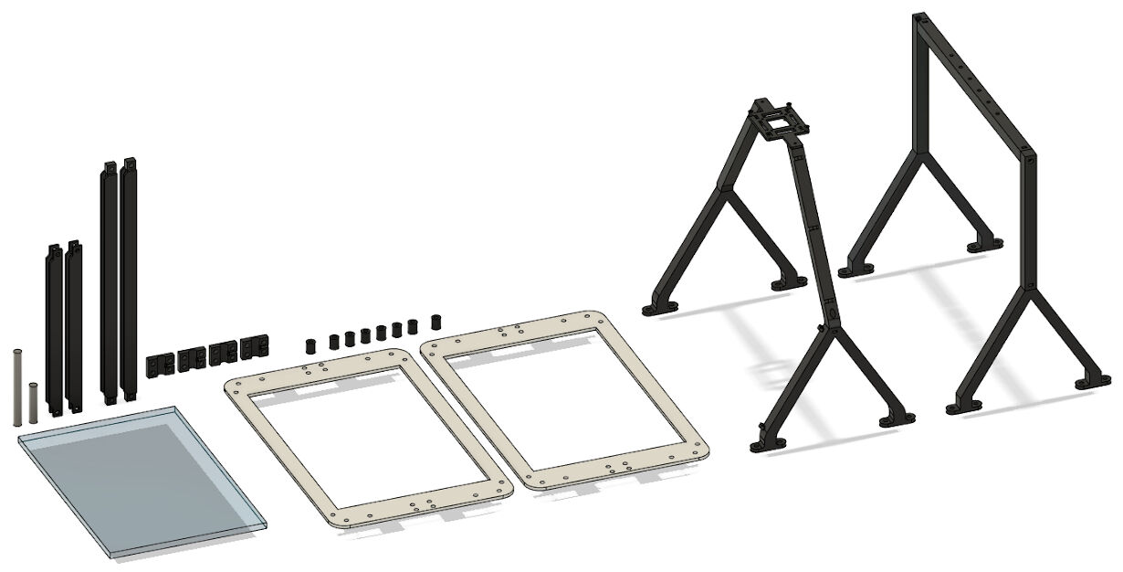
As previously sketched, the general setup consists of mainly two groups of mechanical parts, namely the parts that are suspended by the frame and the frame itself. Therefore, these components, the design of the parts, manufacturing and assembly is described separately below. In the end, the mechanical components are all put together.
Parts Suspended by the Frame
The mechanical parts suspended by the frame are:
- Glass Plate: Dimensions 300 x 200 x 8 mm (w x d x h)
- 3D Printed Profile: Positioning of LED strip, fixing glass to more rigid structure
- Lasercut Frame: Two sheets sandwiching the 3D printed profile
- Rotating Shaft: Diameter 10 mm
- Shaft Mount: Mounting shaft to lasercut frame
- Camera Mount: Mounting camera to lasercut frame
- Couterweight: Balancing the camera's weight
These parts were firstly designed using CAD, then manufactured with different manufacturing processes and lastly assembled.
Computer-Aided Design
Designing the individual parts suspended by the frame was achieved using the 3D CAD software Autodesk Fusion 360. I started with it already in the second week of FabAcademy. Later, I finalized the designed so that they can be manufactured and assembled properly.
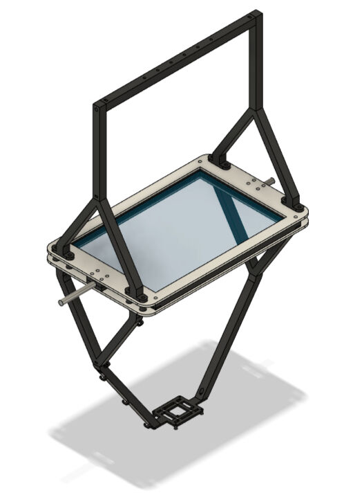
Preliminary CAD
In the second week of FabAcademy, I started with the preliminary CAD design of the parts suspended by the frame using Fusion 360. Please refer to this section for more details on the design.
The parametric design is centered around a glass plate with the dimensions of 200 x 300 mm. From the side, 3D printed profiles can be slid onto the glass plate to hold the LED strip in place, one profile per side. These can be connected by finger joints in the corners and furthermore secured in place by screws traversing though the overlapping parts.

The 3D Printed Profiles
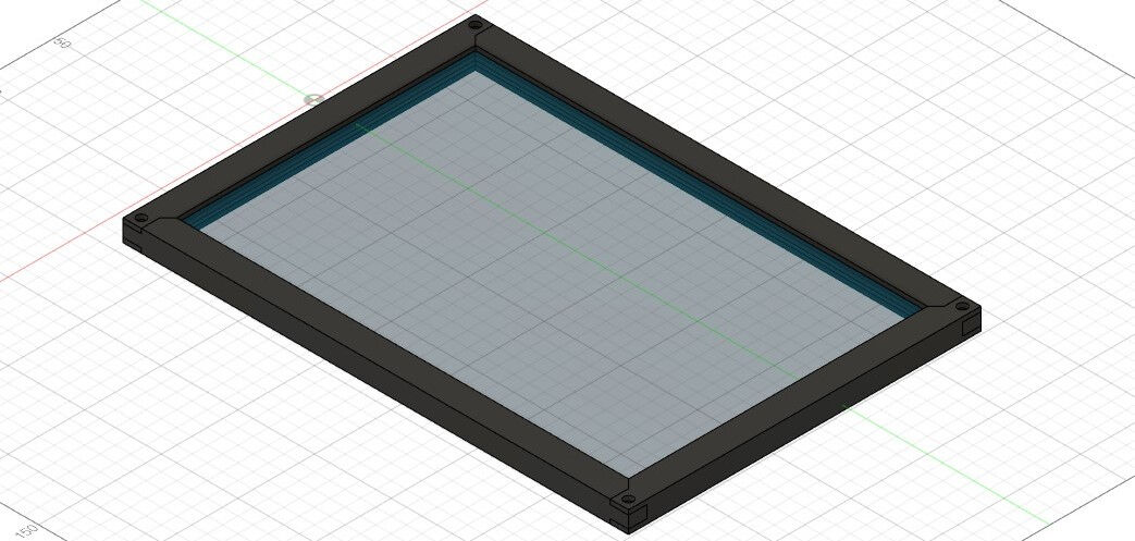
Profiles Assembled Around the Glass Plate
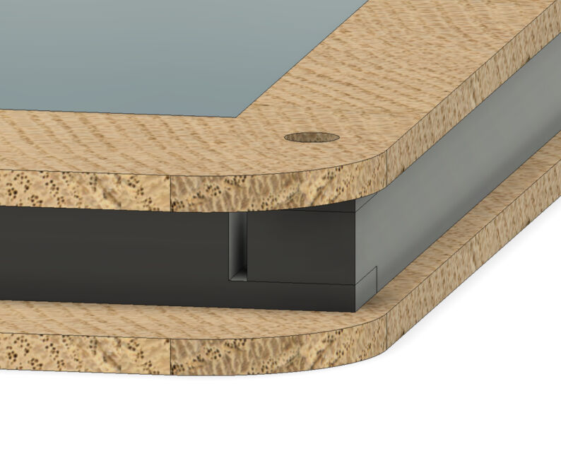
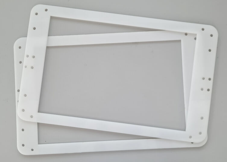
In addition, the profiles are sandwiched by two lasercut frames from the top and bottom, respectively. They are secured in place with the same screws that joins the four profiles at the corners.

Lasercut Frames Sandwiching the Profiles
As you can see in the image above, the lasercut frames protrude from the profiles at both sides creating a slot where a mount for the rotating shaft can be attached with additional screws. As this shaft mount is designed to consist of two halves with a cylindrical slot, tightening the screws compresses the mounts onto the shaft between them. The created friction should prevent any rotation of the shaft in the shaft mounts.
Below, you can see a video showing the complete assembly and an animation of the rotation.

Shaft Mounting Halves Inserted in the Lasercut Frame
Animation of the Rotating Shaft
Final CAD
Later, when I had time for working on my final project between the weekly assignments, I continued to model the parts to generate a final design from the preliminary one shown above.
As the LED strip has now arrived and I could measure the parameters like width and height of it, I firstly entered the correct values for the parameters in Fusion 360. Here, I changed the value of the width of the LED strip to 2 mm.
When reviewing the preliminary design of the parts mounted on the shaft, I noticed that I had to design an inlet or rather outlet for cables supplying power to the LED strip which is enclosed by 3D printed profiles. Designing this however is relatively simple. I just selected the face in the slot at the end of a small profiles and negatively extruded it by the parameter referring to the width of the LED strip. This deepened the slot and allowed the LED strip to escape through it.

Deepening the Slot for an Offset in the Assembly
Offset in the Assembly Allows for LED Strip to Enter the Profiles
Furthermore, the LED strip had to perform sharp corners which however is not possible or would imply high stresses potentially leading to failure. To overcome this problem, I added some dogbone-shaped cut-outs in the corners. In detail, I added a sketch on the side of the profiles which I used to generate a cut-out between the strips holding the glass plate.

Sketch on the Side of the Profiles
Negative Extrusion to Generate the Dogbone Cut-Outs
I furthermore added a fillet on the inner sharp edge with the same radius as the dogbone's circle, namely 10 mm. This resulted in the profiles shown below. At the outlet of the LED strip, I added another fillet for the outer edge with a radius of two thirds of the dogbone's circle.
Long Profiles with Dogbone Cut-Outs
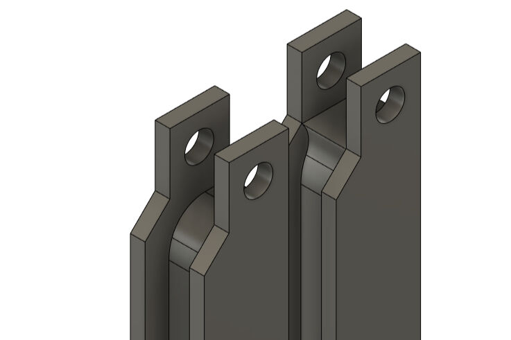
Short Profiles with Dogbone Cut-Outs and LED-Strip Outlet
After assembling the profiles, I investigated the generated cut-outs. You can see them below. As I was happy with it, I left it like this.
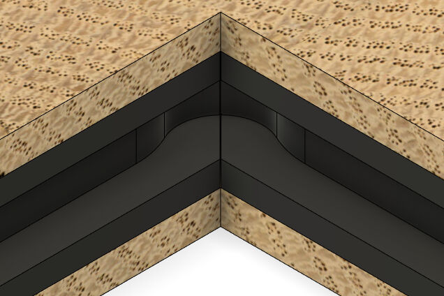
Meeting Point of Two Profiles with Dogbone Cut-Outs
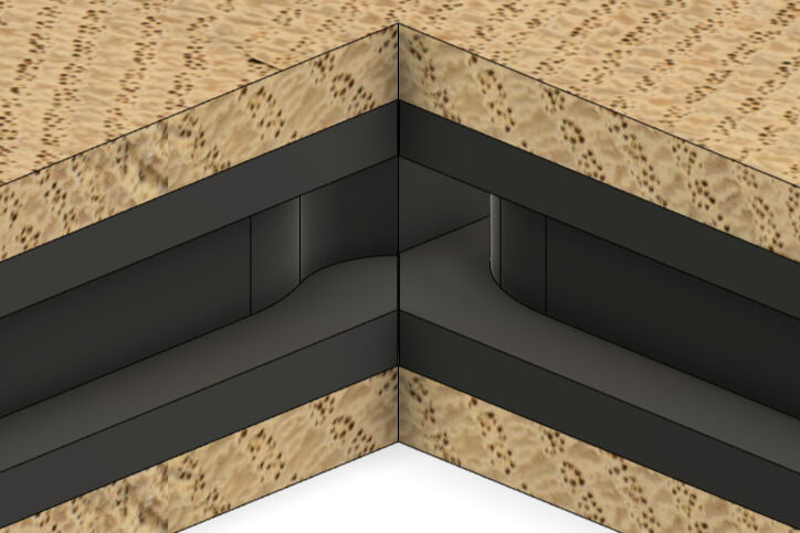
Meeting Point of Two Profiles with Dogbone Cut-Outs and LED Outlet
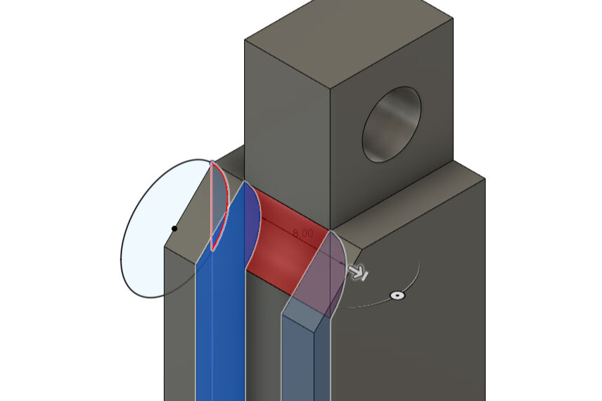
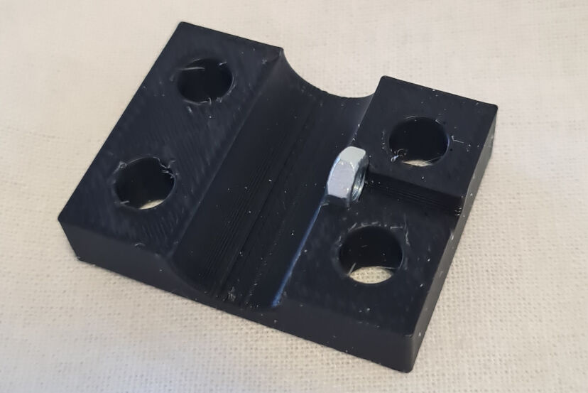
Furthermore, I was concerned whether the shaft mounting halves were able to clamp the rotating shaft strong enough to limit any relative movement between these parts. As I doubted it, I also added an insert for an M3 nut between the two halves and a screw hole. This allowed me to tighten a M3 screw onto a shaft, which I also will file down to have a flat on one side.
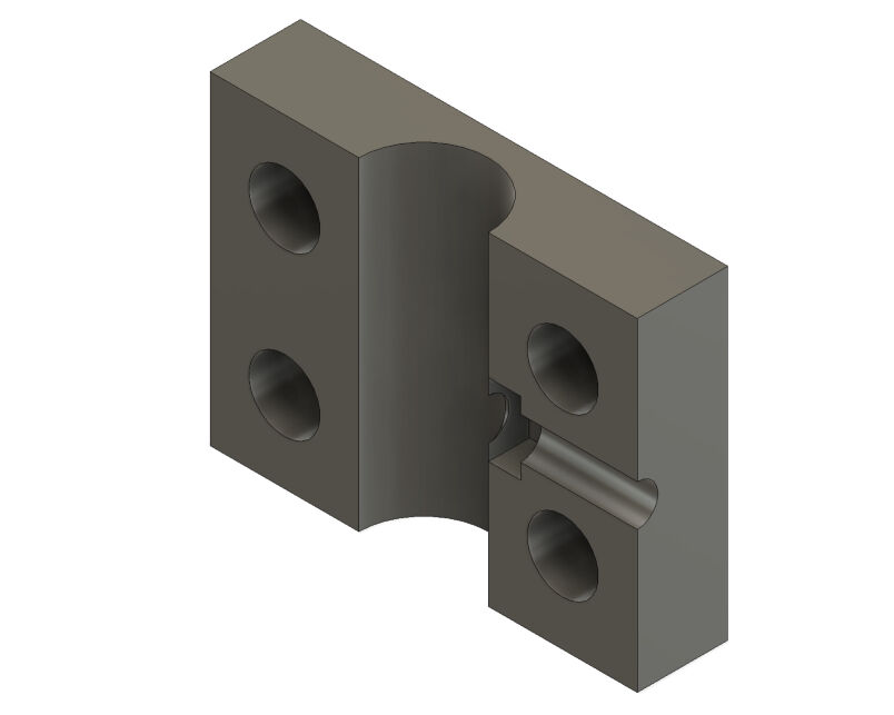
Shaft Mount Half with Nut Insert and Screw Hole

Functional Principle to Limit Relative Rotations of the Shaft and the Mount
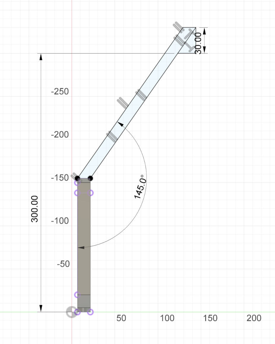
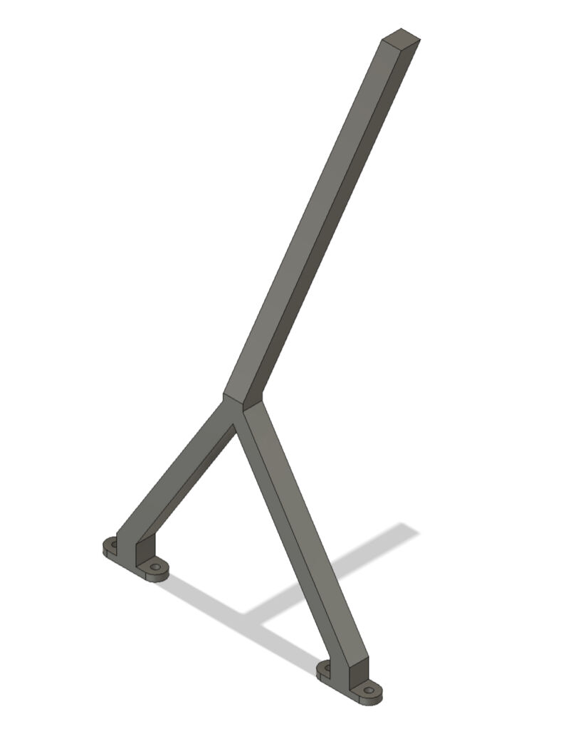
As a last aspect for the parts mounted on the shaft, I had to design the camera mount, its attachment to the remaining components and its counterweight. For this, I decided on 3D printing two upside-down "V", which connect on the tip to an angled bar. These two eventually join in the middle, where the camera should be mounted. In the bottom of the "V", bolts should connect the camera mounts to the lasercut frames. Initially, I the design is a joined body of every parts which I then split into multiple components and added some aspects to join them.
I started the design with the upside-down "V". For this, I firstly drew two mounting structures in the shape of a rectangle with rounded corners and two screw holes in the corners. I extruded the profiles 5 mm and an inner rectangle for 15 mm. This generated the base for the camera mount.
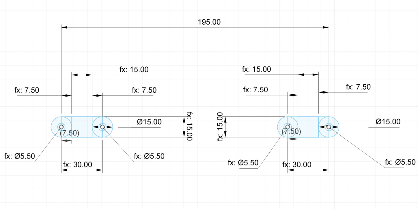
Sketch for the Base of the Camera Mount
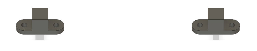
Base of the Camera Mount
Next, I added the actual V-shape by drawing on the side of the mounts. After extruding the sketched profile for 15 mm, I had designed a component that connects the two bases.
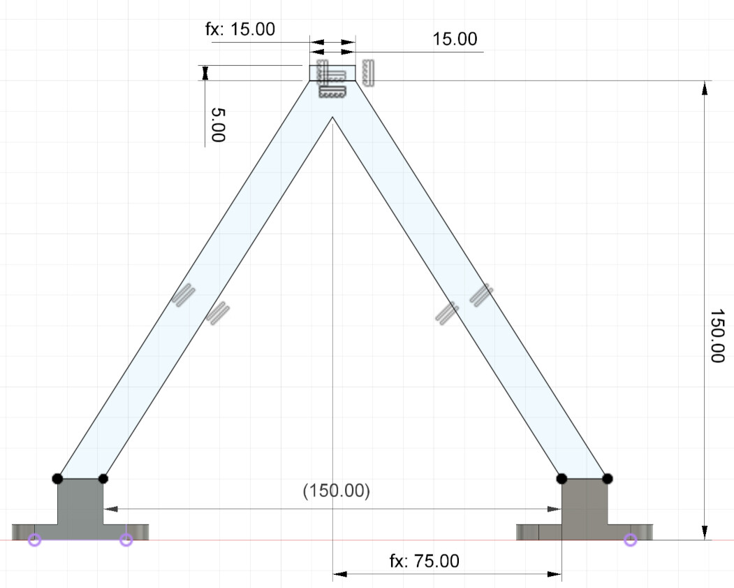
Sketch for the Part in the Shape of an Upside-Down "V"
Part in the Shape of an Upside-Down "V"
I furthermore added the diagonal arm by sketching a profile and extruding it. Here, I specified the height of the arm to be 300 mm with an additional 30 mm to account for the length of the lens of the camera. I chose this height as the angle of the camera's field of view is about 60°. To be able to see the complete glass plate, I had to chose a height of at least 259 mm. However, I did not want to go to that extreme and instead added a safety margin on that.
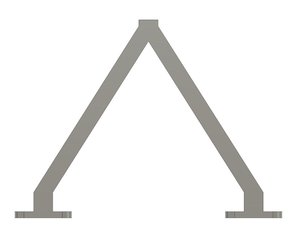
Sketch for the Part in the Shape of an Upside-Down "V"
Part in the Shape of an Upside-Down "V"
Next, I mirrored these arms at a plane in a distance of 168.5 mm from the base. Then, I connected both arms by drawing a sketch on the topmost surface. The generated shape's purpose is to mount the actual camera, i.e. the Raspberry Pi. In this case, I only needed one set of circular holes arranged in a square with an edge length of 58 mm to mount the raspberry pi and another set with an edge length of 30 mm to mount the camera module.

Mirrored Arms
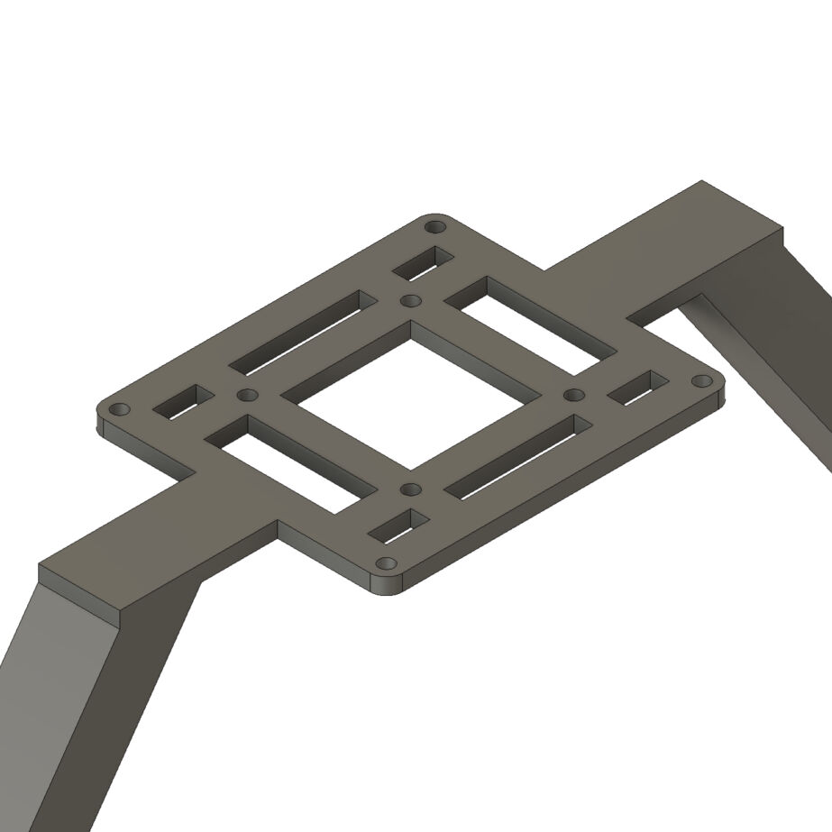
Actual Camera Mount
After that, I added small protrusions acting as spacers to add space between the mount and the Raspberry Pi as well as between the mount and the camera module.
Spacers for Raspberry Pi
Spacers for Camera Module
Once I had the structure modelled, I worked on making it manufacturable, i.e. 3D printable. In this case, I split the body into multiple parts, i.e. two "V"-shaped parts, two diagonal arms, the camera mount with the spacers for the Raspberry Pi and into four spacers for the camera module. For this I simply used horizontal planes placed at the desired positions.
Next, I had to design the joints of the individual pieces. For the joint between the "V"-shaped part and the diagonal arm, I used a nut insert and circular hole for a bolt. For the joint between the diagonal arm and the camera mount, a simple circular hole was needed where a bolt can be inserted and a nut can be tightened onto it.

Joint of "V"-Shaped Part with diagonal Arm

Joint of Camera Mount with diagonal Arm
As a power supply and a connection to the remaining electronics will be necessary to run to the camera, I added some cable clips where the cables can be inserted and fixed. For this, I drew a sketch on a plane orthogonal to the outside face of the diagonal arm and one of the "V"-shaped part. I extruded it for 3 mm at different position along the parts.

Sketch for Cable Clips
Cable Clips on Diagonal Arm and "V"-Shaped Part
To attach the complete camera mount to the remaining components, I had to make some screw holes in the lasercut frames. At the according positions, I created circular holes with a diameter specified with the parameter referring to the screw's diameter.

Added Screw Holes for the Camera Mount on the Lasercut Frames
The appearance of the lasercut frames were furthermore changed to a white plastic, namely "Plastic - Glossy (White)".
Lastly, I added some spacers that can sit between the two lasercut frames to be able to tighten screws around them without bending the frames or adding to much stresses. These are just a cylinder with a diameter of 11.5 mm and a circular hole in its middle with a diameter of 5.5 mm. The latter dimension is the adapted value of the parameter referring to the screw's diameter.
Last but not least, I also had to design the counterweight of the camera. I intentionally design the whole project with a small and thus cheap motor which however results in the fact that the motor cannot turn the off-balanced camera and the other components on the shaft. To bring everything in balance and with this allow the motor to turn the shaft, a counterweight is added opposite of the camera relative to the rotating shaft.
Spacers Between the Lasercut Frames
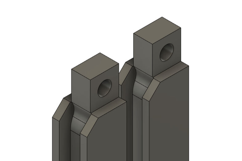
In principle, the design is very similar to the complete camera mount. However, instead of diagonal arms, the arms above the "V"-shaped parts are placed vertically to allow the user to easily access the glass plate to place animals on it. The top ends of the vertical ars are connected by a crossbar with holes in it to allow to attach some weights out of metal to it.
The whole mount for the counterweight consists of five parts, the two "V"-shaped parts, two vertical arms and a crossbar. They are joint by M3 bolts and nuts which can be inserted into the according positions.
Mount for Counterweight

Joint Between Individual Parts of the Counterweight Mount
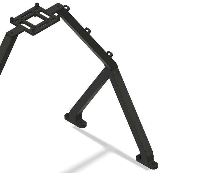
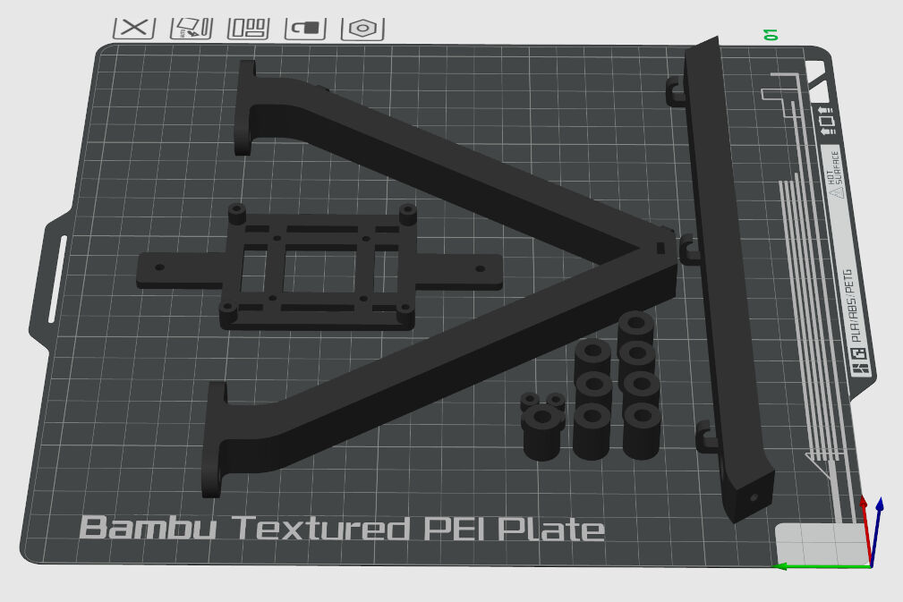
With this, I had finalized the design for the components on the shaft. You can see the individual components below.
All Components on the Shaft
As for the assignment on computer-aided design, I assembled the components. Please refer to this assignments for the details of how to assemble components in Autodesk Fusion 360.
In principle, I repeated the steps for the newly created components in order to get the assembly of all components. Not shown are bolts and nuts.
All Components on the Shaft Assembled
Manufacturing
The manufacturing of the components on the shaft were initiated with 3D printing on a BambuLab X1 Carbon. The details on 3D printing can be seen here.
From Fusion 360, I exported the parts as .step files and opened them with the slicer software Bambu Studio. In the assignment on 3D printing, I found the "0.16mm Optimal @BBL X1C" the best and therefore, I also selected this profile. I left all settings as the default and just printed the parts with black PLA.
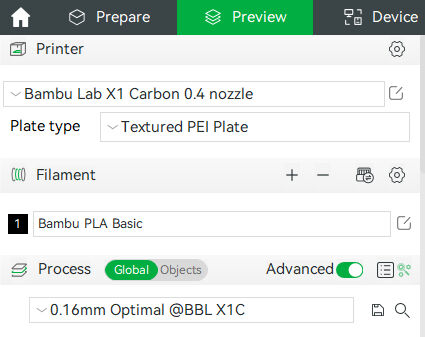
Settings for 3D Printing
Below, you can see how the parts were oriented for 3D printing. The parts that are not shown are oriented accordingly. The shaft mount halves were oriented such that the layed on the large flat side.
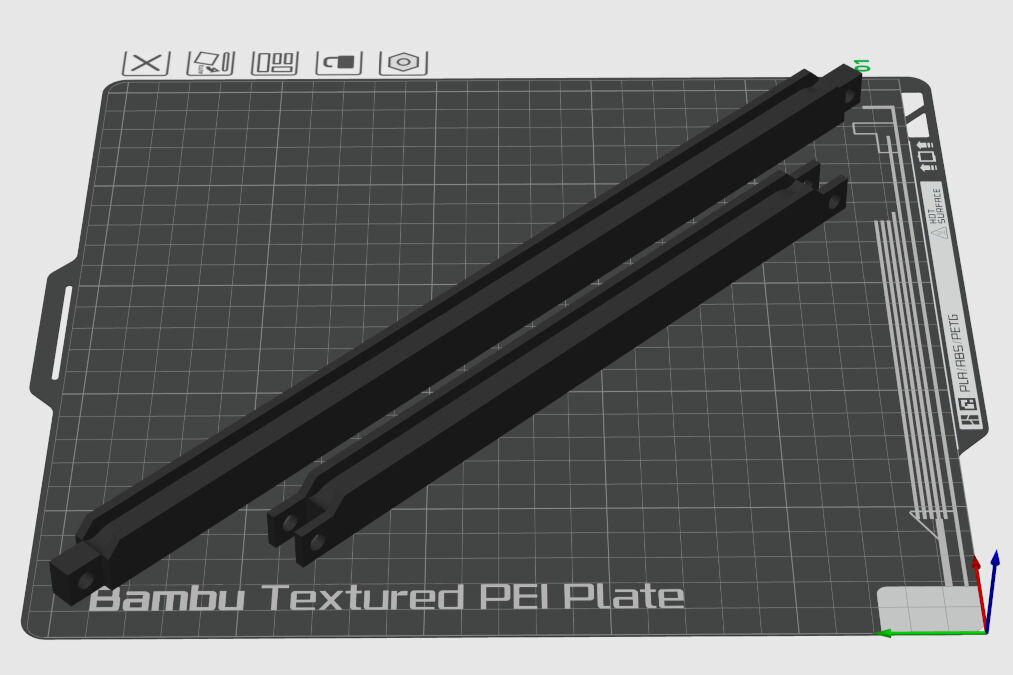
All Components on the Shaft
All Components on the Shaft Assembled
Next, I produced the lasercut frames from 3 mm thick sheets of POM. Instead of the lasercutters in the FabLab Kamp-Lintfort, I used the lasercutter on the campus in Kleve. As I also have never used POM sheets, I had to find the optimal lasercutting settings for it. In general, I firstly drew two small rectangle approximately of the size 1 cm x 1 cm in the software RDWorksV8. Both had different colors which allowed me to set different lasercutter setting for them. However, I did not concern about them as they can be set at the lasercutter itself. I simply pressed "SaveToUFile" in the bottom right and saved the .rd file on an external flash drive.
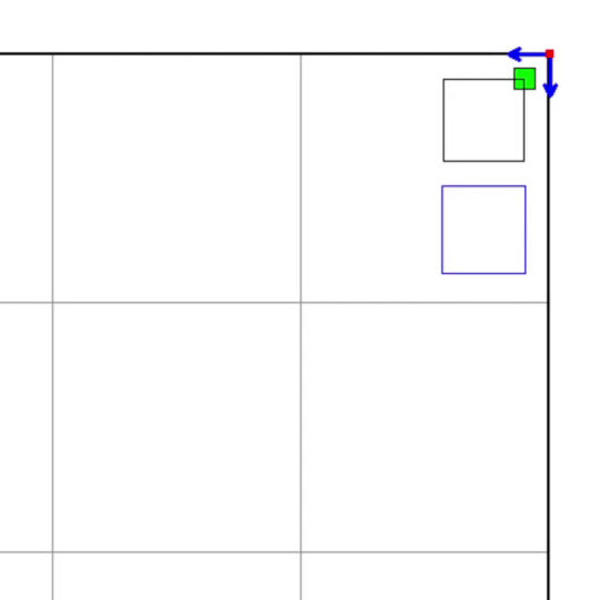
Rectangles in RDWorksV8
At the lasercutter, the LM500700 80W, I firstly had to turn on the socket in the back right that also immediately switches on the lasercutter's extraction. The lasercutter is then powered by turning a switch on the right of the machine.
The lasercutter has a display with buttons that allow the user to control the machine, e.g. to set the origin, select a file and start the lasercutter job.
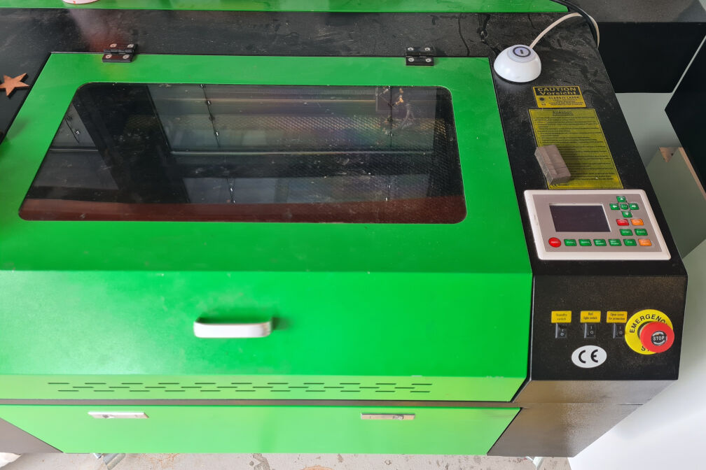
The LM500700 80W Lasercutter
After plugging in the flash drive on the right into the slot called "U-disk", I selected the lasercutting file by pressing File, navigating with the arrow keys to "Udisk+" and entering. Then, I selected the file and entered again which lead to three options. Here, I selected "copy to mem" to copy the file to the memory.
Next, I placed a sheet of POM in the center of the lasercutter's bed and moved the lasercutter head to the top right corner of the sheet. Then, I pressed the button "Origin" to zero the axis.
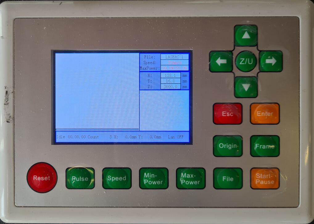
Display of the Lasercutter
I furthermore used a 15 mm thick block of metal to focus the lasercutter head by positioning it exactly 15 mm above the sheet of material. Here, I used two buttons, one for moving up and one for down on the right of the machine. It did not require any saving and hence I proceeded with the settings of the cut.
As the file was imported to the memory, I could just press "Enter" twice to reach a settings panel. By clicking through the parameters with the "Z/U" button to power and speed and using the arrow keys for increasing or decreasing the values, I set the power initially to 80 and the speed to 40, the parameters for this lasercutter that are typical for this plywood.
Once, everything was set, I started the lasercutting job by pressing the "Start - Pause" button. This immediately started cutting with the previously set settings.
However, the first test cut did not cut at all and therefore, I drastically reduced the speed and started the test again. I repeated the testing with different parameters. In the end, I found a speed of 20 and a power of 70 ideal to cut the test rectangles.
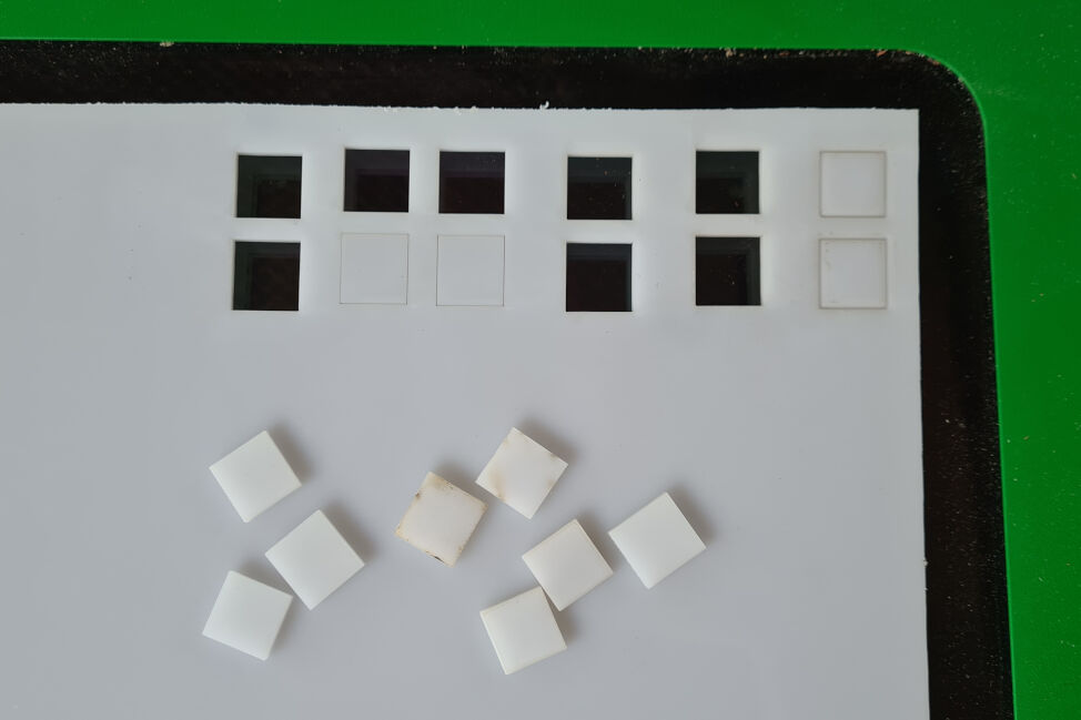
Test Cuts on the Lasercutter
Next, I started cutting the actual files. For this, I exported the desired face of the lasercut frames as an .svg file from Fusion 360 using the Origin plug-in. This .svg was then imported into Inkscape and exported as a .dxf file (version R12). This file format can then be imported into RDWorksV8.
Next, I changed the settings of the lasercutter in RDWorksV8 to a speed of 20 and a power of 70 and exported from this project an .rd file to an external flash drive. The file on that drive was then again saved to the internal memory of the lasercutter. Once that file was selected, the display of the lasercutter showed the file on the left and the settings on the right.
Then, I placed a sheet of POM with 3 mm thickness on the lasercutter's bed. Here, I noticed that the sheet was slightly bent. As any deviations of a flat sheet of material in suboptimal for cutting, I decreased the speed to 15 as shown in the image.
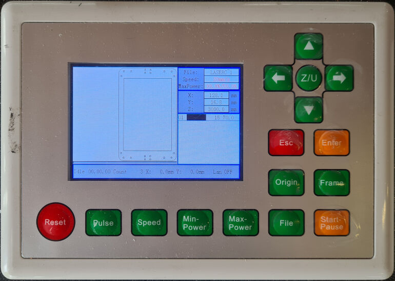
Display of the Lasercutter with the File and Settings
Once I set the origin, I started the job. After it was done, I repositioned the origin further to the left and started the job again. Thus, I cut this part two times. As visible in the image below, the cut components were however stained with burning marks. Here, I simply used a paper towel and isopropanol to wipe of the stains.
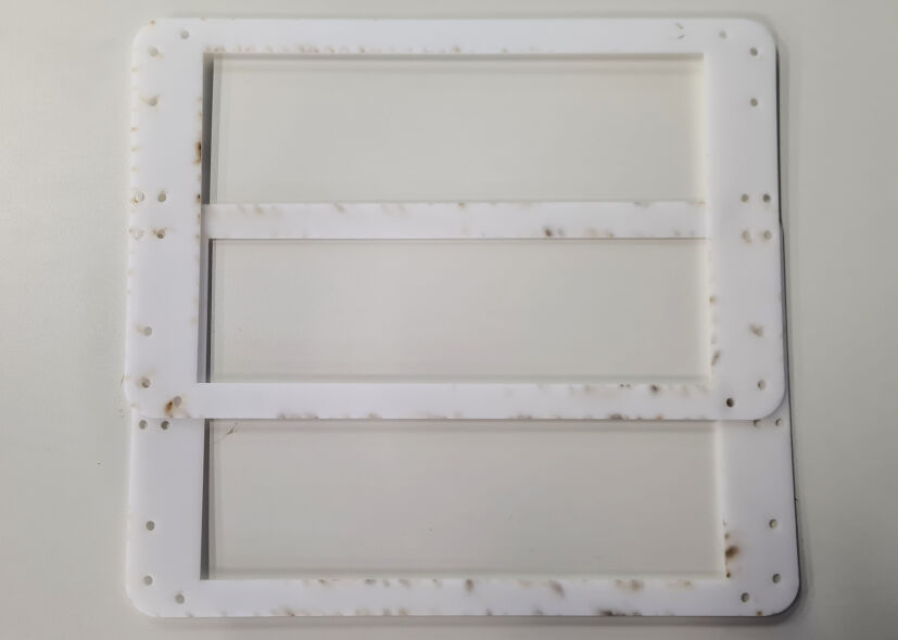
Lasercut Frames Before Cleaning with Isopropanol
Lasercut Frames After Cleaning with Isopropanol
The Frame
In addition to the parts that are suspended by the frame, the frame itself must be designed, manufactured and assembled. In contrast to the other mechanical parts, these steps were completed for a single assignment, namely for computer-conntrolled machining. Please refer to its documentation for more details as below only a summary of the steps is described.
Computer-Aided Design
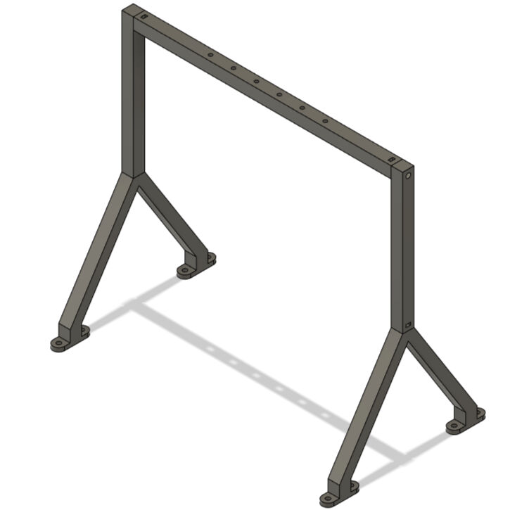
The design of the frame was also done in Fusion 360. It consists of many parts that are all joined by finger joints and press fits. The two sides are connected in the top by a straight crossbar and in the back by an X-shaped crossbar. This structure is mounted onto a baseplate. At about half the height, the two sides of the frame have a cylindrical hole where the bearings for the rotating shaft can be inserted. To make the suspension of the rotating frame more stable, two bearings on either side of the frame are used. Therefore, a second layer of the material is used to thicken these parts.
On one side however, the motor must be mounted. Therefore, the second layer of the material is placed in an offset and elongated. On its top, a stepper motor (NEMA 17) can be fixed such that its shaft protrudes into the space between the two layers of material. This creates also space to run a belt from the motor shaft in the top to the rotating shaft connected to the glass plate in the bottom.
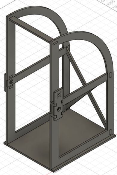
Complete Assembly
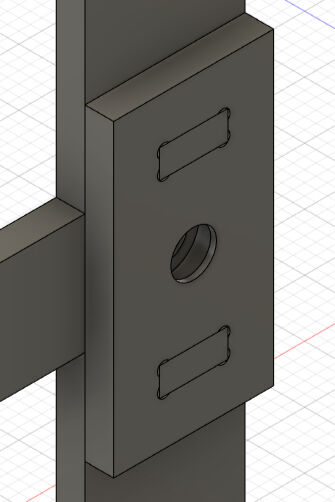
Panel for Mounting the Second Bearing on the Left Side
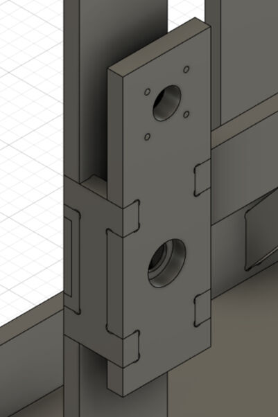
Panel for Mounting the Second Bearing and Motor on the Right Side
Computer-Aided Machining
After the design was completed, the manufacturing must be prepared with computer-aided machining (CAM) which is also done in Fusion 360. For this, nesting must be accomplished, i.e. arranging all parts on a single sheet of material with the aim of minimizing the waste of material. This is done by placing the parts on the same plane in the correct orientation and moving them such that only the milling tool fits between them.
Then, the toolpaths can be generated. Here, certain milling techniques like "2D Pocket" or "2D Contour" are selected for the according feature. After having selected all necessary aspects, the toolpaths can be exported as machine code with the according post-processor.
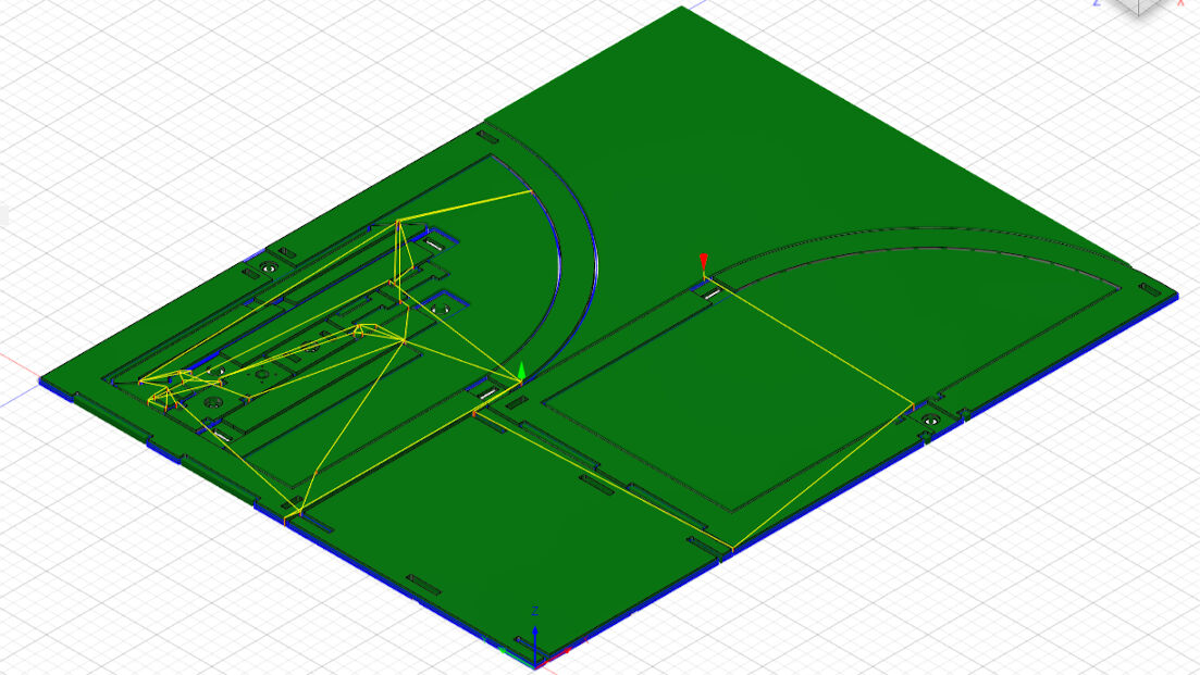
Finished CAM: Cut Stock (Green) with Toolpaths
Manufacturing
The machine code obtained by CAM can then be opened in the software for the machine. After fixing the material and setting up the machine and software, the milling job was started.
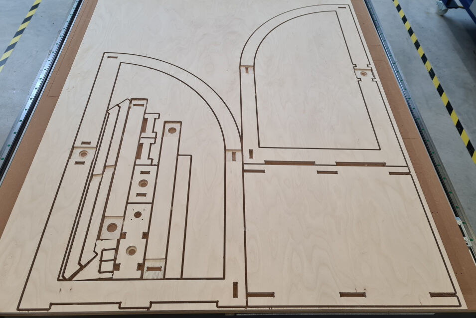
Done Milling Job
Assembly of the Frame
Once the milling job is done, the parts need to be post-processed with a bit of sanding, tab removal and so on. Then, I started with the assembly using a mallet and a sacrificial piece of wood to hammer the press fit joints together. The tolerances were quite low which is why I also had to further sand some joints. But after a while, the assembly was complete. I am really happy about how this turned out.
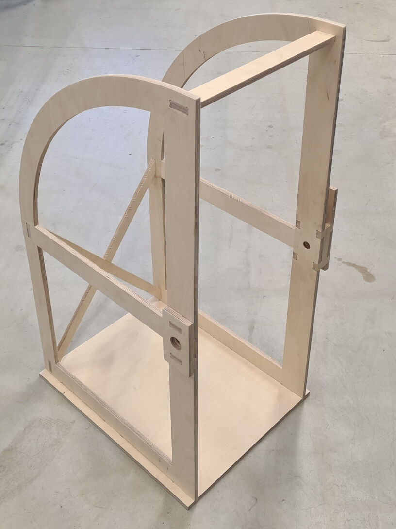
Assembled Parts from the Left
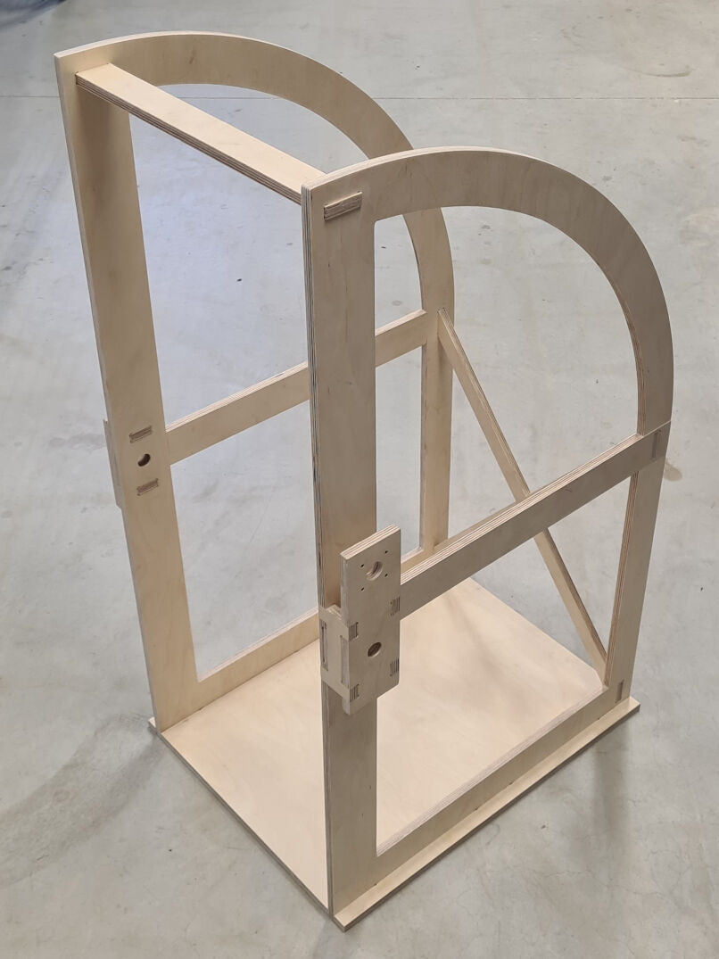
Assembled Parts from the Right
Assembly of All Mechanical Parts
Now, that the frame is assembled and the components suspended by the frame are fabricated, the assembly can begin. For this, I started with the center part of the project, namely the glass plate and the LED strip.
For this, I layed down the glass plate on a table and the LED strip and profiles around it. Here, I already matched the outlet of the LED strip's cable in the profile with the LED strip. Next, I placed the end of the LED strip at the corner of the glass plate where the outlet will be placed, at the other face however. I held the LED strip in position at the face while mounting the profile from the side. I continued with this for the next side face of the glass plate. As soon as I had two profiles joined in the end, I used an M4x25 bolt and nut to secure their position. I proceeded with this technique until I had looped the LED strip around the glass plate with the profiles mounted over them.
While these profiles, the LED strip and glass plate layed assembled on a table, I simply removed the nuts and placed one of the lasercut frames on the bolts. After fixing its position with the nuts, I turned everything around and repeated the process with the second lasercut frame. After I had assembled the lasercut frames with the profiles, the glass plate and the LED strip, I replaced the nuts with lock nuts.
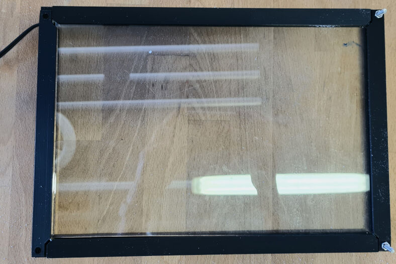
Profiles Around Glass Plate with LED Strip
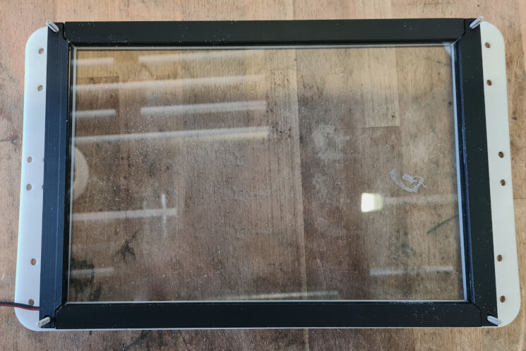
Lasercut Frame on Profiles
After I finished this, I started assembling the shaft mount halves. For this, I firstly placed a nut in one of the halves of the shaft mount, then put the second half on top of it and, while holding it in this position, I inserted an M3x16 bolt into the nut. As the assembled two halves were really fragile, I clamped them together by inserting them in their according position between the lasercut frames with only one M4x20 bolt and lock nut so far. This made it easier to assemble the parts suspended by the frame with the shaft later.
Assembling the Two Halves of the Shaft Mount
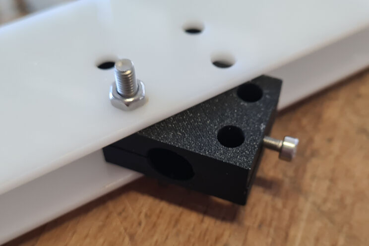
Assembling the Shaft Mount with the Lasercut Frames
Next, I continued to mount the shaft to the frame. For this however, the first step is to position the ball bearings. As the tolerances were relatively low during the CNC milling of the frame, I was not able to do this by hand and instead a bearing press was needed. For this, I disassembled the mounting panels on the side of the frame such that each hole for the bearing was separated. Then, I pressed the bearings into the four holes with a bearing press, one after another.
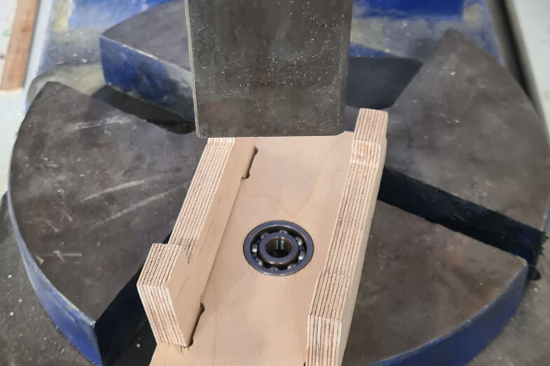
Using the Bearing Press to Press the Bearings into the Frame
After this, I wanted to place the shaft in the bearings and mount the panels back onto the frame. However, I then discovered, that the shaft also needs to be inserted with a bearing press. Therefore, I pressed the two shaft parts on either side into the mounting panels up to the desired position. Before mounting the panel back onto the frame, I however also placed a pulley on the shaft below the motor fixture, tightened its set screws and used four M3x16 bolts to fix the position of the motor on the panel.
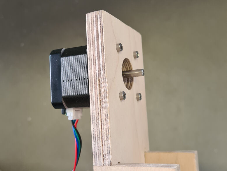
Fixing the Motor to the Motor Mounting Panel
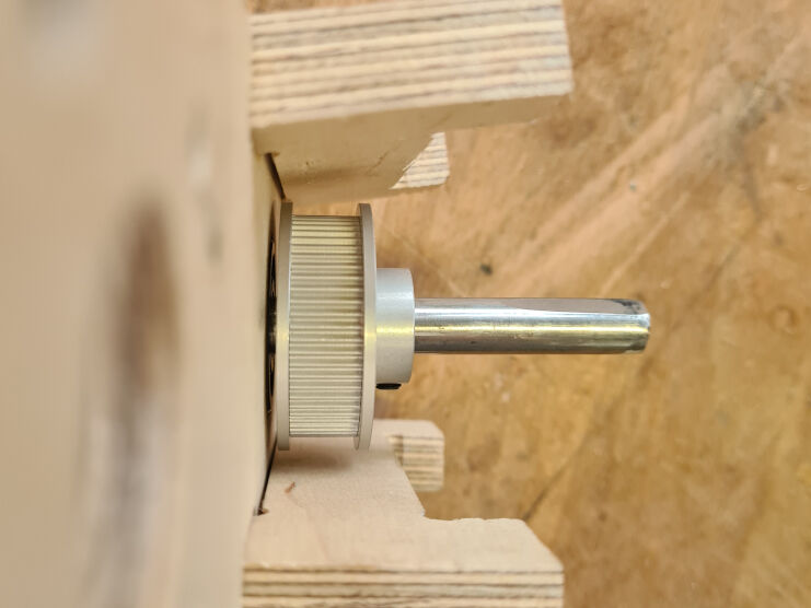
Placing the Pulley on the Shaft
Then, I was able to mount the panels back onto the frame. For the beginning, I used the bearing press. However, as soon as the frame parts came together, I was not able to use the bearing press anymore as it would have pressed out the bearing from the frame. Instead, I used a mallet and a sacrificial piece of wood and hammered the pieces together.
Consecutively, I addressed the transmission of the motor's rotation from a smaller pulley with 12 teeth to the shaft with a pulley of 60 teeth. For this, I cut a 6 mm wide GT2 belt to a length of about 293.004 mm. I obtained this length from a formula shown here. With the according teeth numbers and a distance of 110.5 mm, I calculated that the GT2 belt should have exactly this length. Then, I searched online on how to properly join the ends of the belt and found this tutorial. I followed the steps which are firstly joining the ends with superglue and after it had cured slightly, strengthen the joint with a piece of ribbon on the outer face and superglue. As the pulleys were already mounted, I had to place the belt already next to the pulleys while conducting this procedure.
After the ends were joined, I placed the belt on the pulleys. This was slightly tricky as the belt was sized really well and had a healthy amount of tension. However, the pulleys have a protruding edge to avoid any slippage of the belt which makes it difficult to pull the belt over this edge. Therefore, to mount the belt on the pulleys, I had to dismount the pulley from the motor, place it with the other pulley in the looping belt and lastly mounting it back onto the motor shaft.
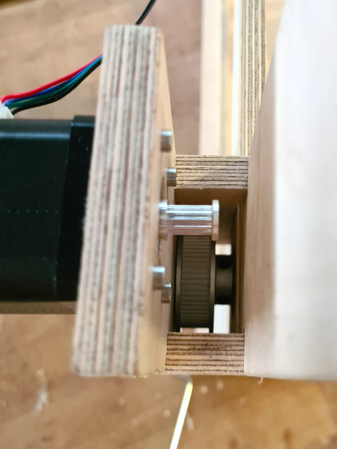
Two Pulleys with a Gear Ratio of 5
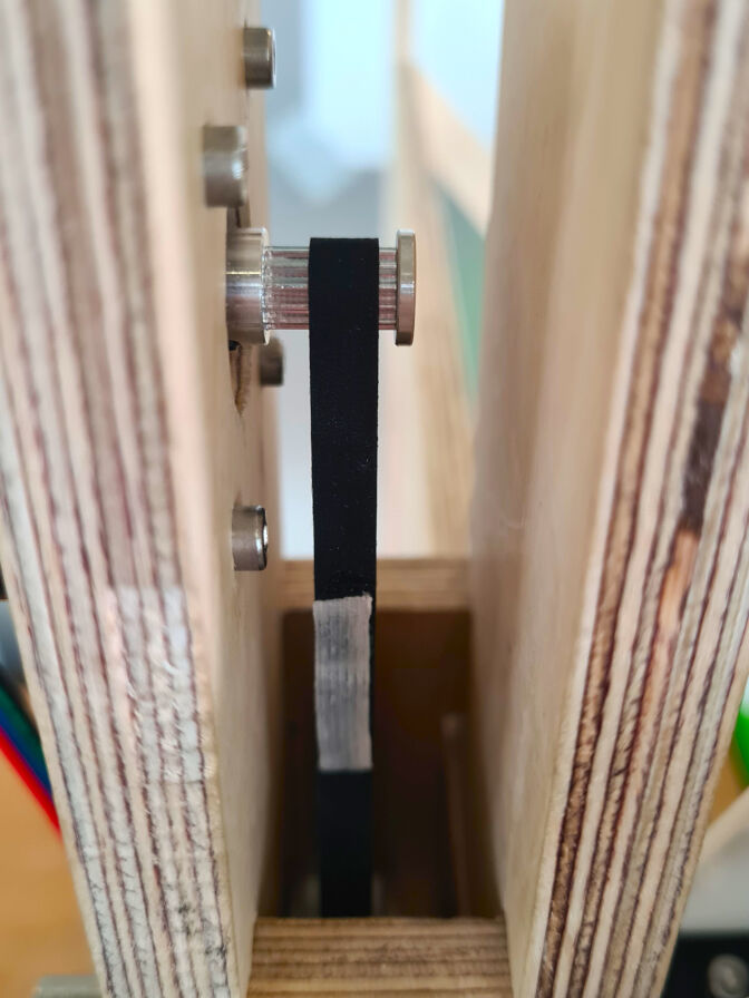
Creating a Looping Belt with Superglue and a Piece of Ribbon
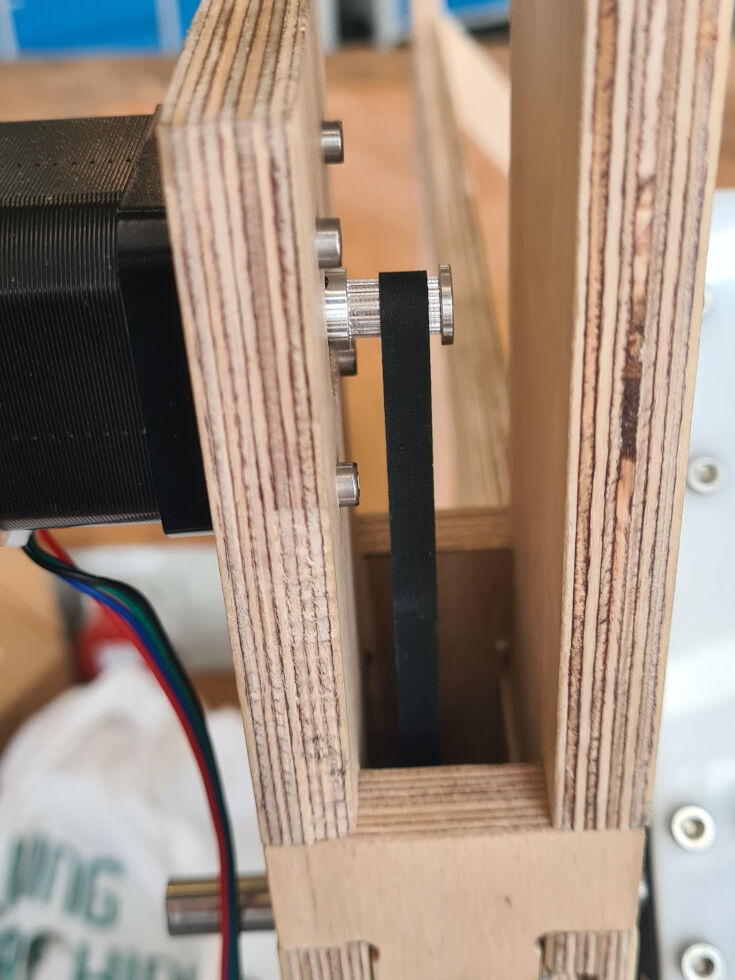
Final Assembly of Motor, Pulleys and Belt
Once, these pieces were assembled, I returned back to the parts suspended by the frame. I placed these parts on the shaft by inserting the rotating shaft in the shaft mounts. Next, I placed the remaining three M4x20 bolts around the lasercut frames through the shaft mount and secured the position with lock nuts. I also replaced the nut of the fourth bolt with a lock nut.
Finally, I only had the camera mount and the counterweight left. I assembled both by using in total two M3x10, four M3x16 and two M3x20 bolts with nuts.
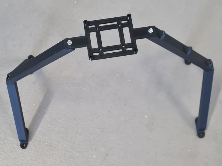
Assembled Camera Mount
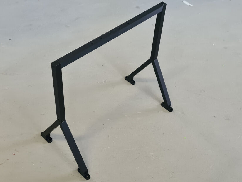
Assembled Counterweight Mount
Additionally, I mounted these to the rest of the parts with eight M4x40 bolts and lock nuts. For this, I placed the spacer between the two lasercut frames and then inserted the bolts through one mount, the sandwich structure of lasercut frames and spacer and the other mount. A washer was furthermore placed between the mounts and the bolt heads or the lock nuts, respectively.
Furthermore, I placed the Raspberry Pi camera with the board and the camera module with the attached lense on the camera mount with four M2.5x10, four M2.5x14 bolts and nuts. To balance the camera, I furthermore needed a counterweight. Before mounting the camera, I used a kitchen scale to estimate its weight, namely 135 g. Therefore, searched in our scrap metal box for a piece of similar weight. Here, I found an approximately 220 mm long aluminum profile with a rectangular face of the size 20 x 20 mm, a wall thickness of 2 mm and a weight of 132g. I used a calliper to mark the position of the screw holes on it to fix it on the mount. Then, I used a 5 mm drilling bit to create the holes. Lastly, I sanded it and mounted it to the counterweight mount using four M4x20 bolts and nuts.
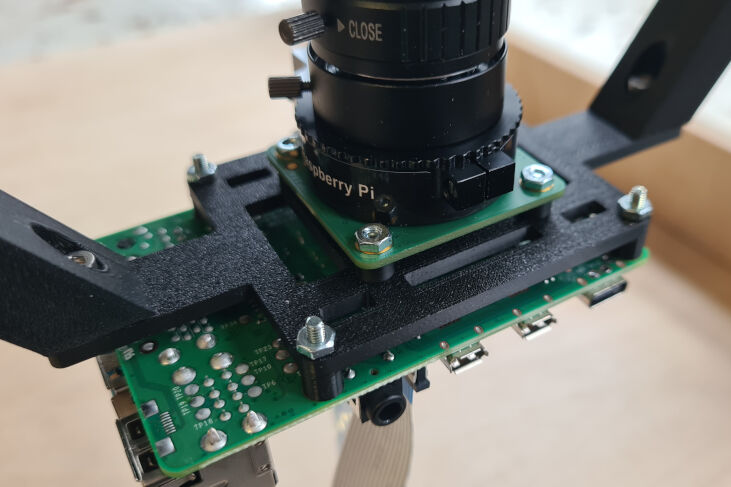
Camera on Camera Mount
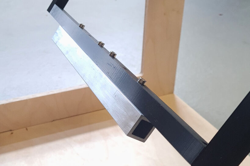
Counterweight on Counterweight Mount
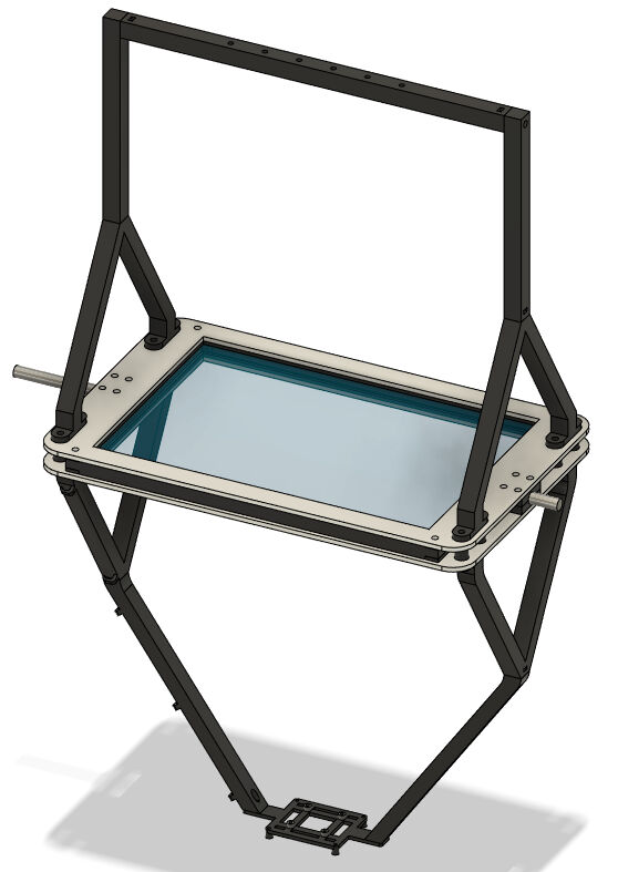
With this, I was finished with the complete assembly of the mechanical parts. Below, you can see the outcome of it. Please note, that the housing for the Raspberry Pi camera is from a later stage of the project, namely system integration. The according assignment can be found here.
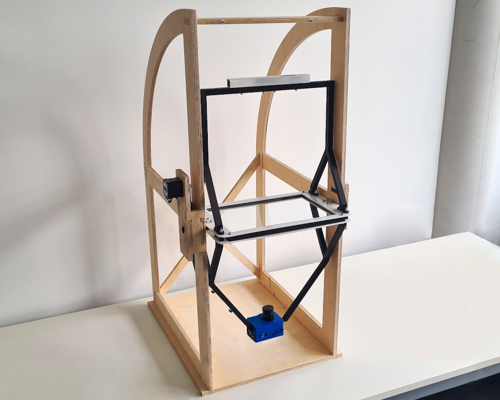
Complete Assembly of All Mechanical Parts
Electrical Components
In addition to the mechanical parts, electrical components are needed. These include a printed circuit board (PCB), some output devices, i.e. a motor and an LED strip, and input devices, i.e. an angular sensor and a camera.
The Printed Circuit Board
In the eighth week about electronics design, I made use of the assignment to make a PCB for my final project. Below, only a summary is shown. Please refer to its documentation for further details.
Before starting the design and consecutively the manufacturing, I had to consider what other electrical components are necessary and how they are connected to my PCB. For the stepper motor, a motor driver is needed, the LED strip requires a MOSFET for controlling the brightness and, to measure the angle of the rotating shaft, a Hall sensor is needed. Lastly, to power the motor and the LED strip, connections to an potential external power supply must be an implemented.
Design With KiCAD
The design of firstly the schematics with its logics and secondly the physical layout of the PCB was done in KiCAD. In the image you can see the outcome of the design phase. From KiCAD, Gerber files are exported.
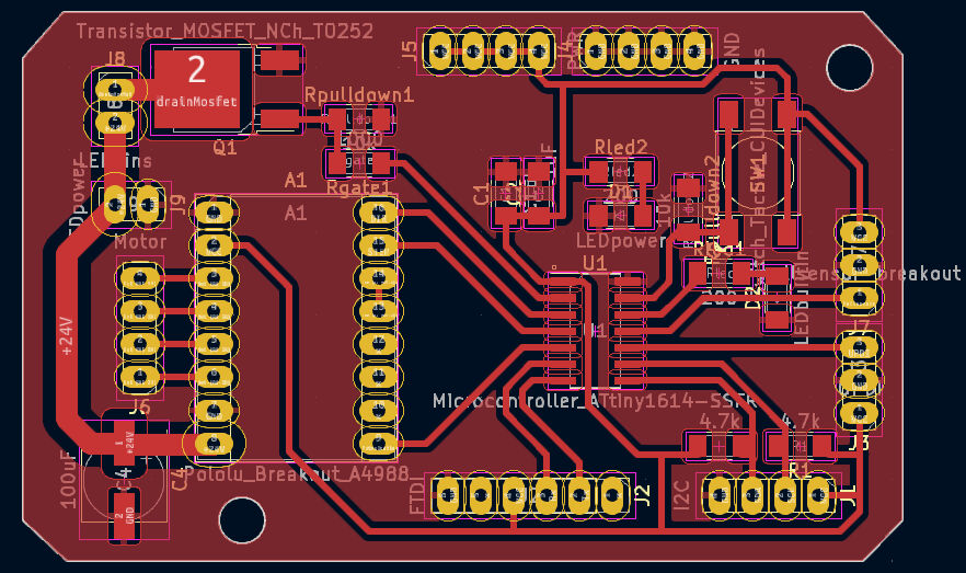
Completed PCB Layout
Computer-Aided Machining & Milling
The Gerber files can then be imported into the software LPKF CircuitPro for the PCB milling machine, the LPKF ProtoMat 1S04. This software is really handy as it also includes the CAM processing. This includes e.g. selecting a tool and defining the starting point of the milling job.
After the CAM processing was completed, the milling can start which is guided with a Wizard in the software for the machine. This really comes in handy as the user basically cannot miss a step with these steps being very well automated, e.g. setting the height of the tool.
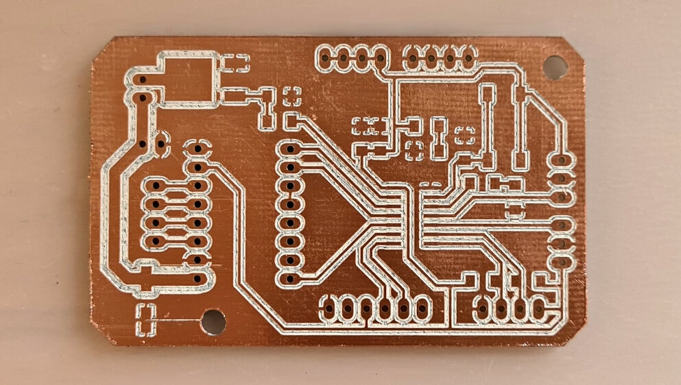
Milled PCB
Soldering
After the milling, the board can be stuffed with the components by soldering. This includes the microcontroller, capacitors, resistors, LEDs, buttons, pin headers, the MOSFET and other comonents.
Lastly, a bit of testing is completed with a multimeter to ensure the functionality of the PCB. The board I made is shown in the images below.
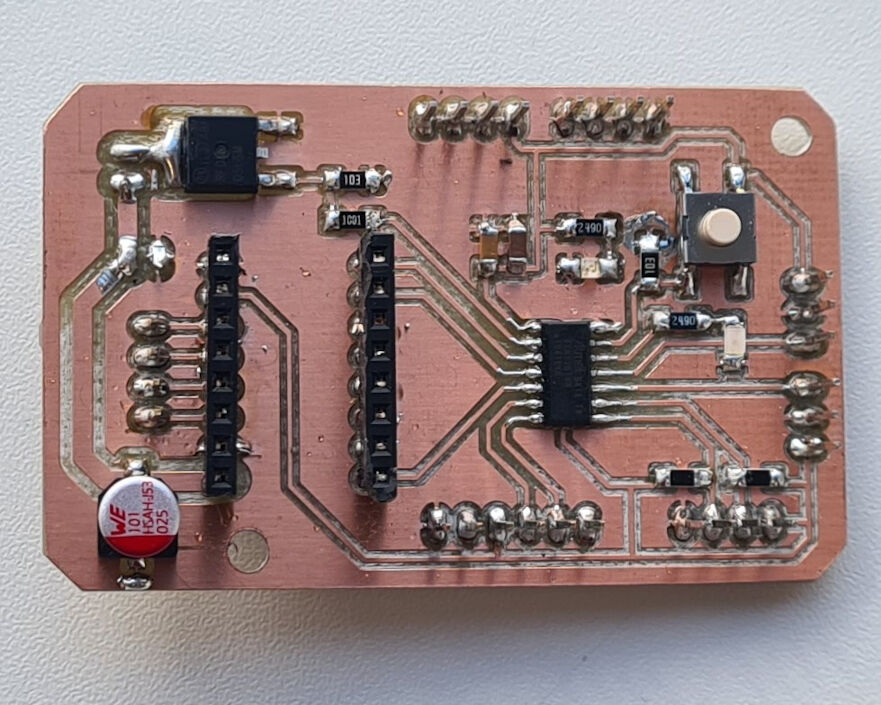
Finished PCB

Angled View on Finished PCB
At a later stage of my project, I figured out, that I will need microstepping of the stepper motor with a step size of 1/16th of a complete step for a slower rotation speed. However, in my design of the PCB, I had not included any possibility of controlling the step size of the motor. As a workaround, I soldered the microstepping pins of the motor driver together and soldered a wire from the 5 V pin to one of the microstepping pins on the back of the PCB.
Soldering the Microstepping Pins together for 1/16th Microstepping
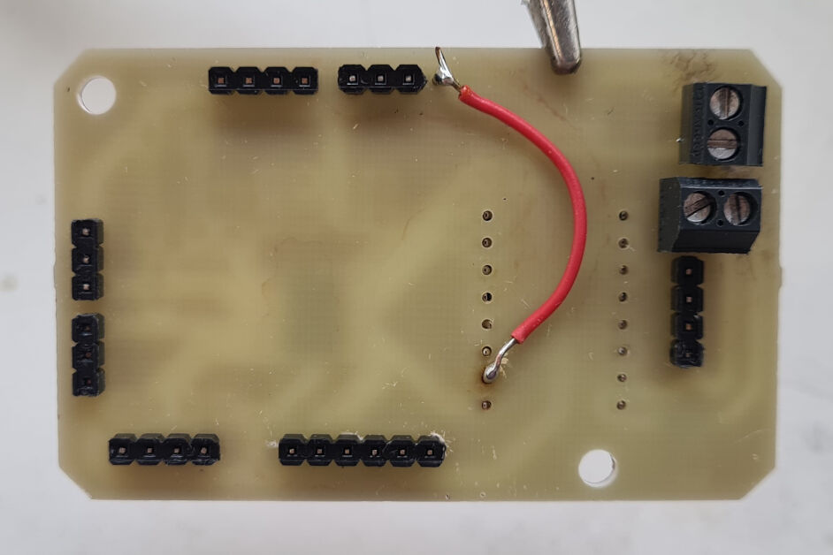
Soldering the Microstepping Pins to 5 V for 1/16th Microstepping
With this, the microstepping pins are constantly at a high voltage level allowing me to achieve 1/16th of a complete step as a step size and thus a lower rotation speed.
Output Devices
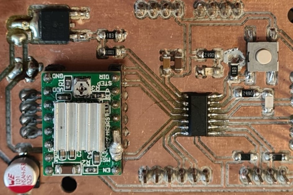
The output devices for my final project are a stepper motor and an LED strip. To explore how to control then, I used the assignment on output devices. Once, I had finished the PCB for my final project, it was very easy to control the output devices as most of the wiring is already implemented on the PCB. For more details than shown below, please refer to the documentation on output devices.
Controlling the Movements of a Stepper Motor
For controlling the stepper motor, I mounted the driver onto the female pin headers on the PCB in the correct orientation, connected the motor to it and attached a bench power supply with 24 V and a load-depended current to it. Then, I attached a programmer board to the PCB via the 1x3 pin header for UPDI, including VCC, ground and the UPDI pin. Then, I wrote an Arduino sketch shown here and uploaded it to the microcontroller. This made the motor spin back and forth with a small pause between it.
Motor Rotates Using the Final Project Board
For more details, please refer to this documentation. It shows how a single step is programmed and that a loop repeating the single step creates the rotation of the motor.
Controlling the Brightness of the LED Strip
For the LED strip, I controlled the brightness with a MOSFET which is basically a voltage-driven gate. By opening and closing it via pulse width modulation (PWM) with different duty cycles, the "subjective" brightness can be adjusted. This is "subjective" as the brightness actually does not vary but just the "On" time vs "Off" time such that it is only perceived as a changed brightness.
For wiring the components, I firstly connected the LED strip and a bench power supply with 24 V and a load-depended current to the according screw terminals. Then, I also connected a programmer board via the UPDI pin header and uploaded the Arduino sketch shown in this section to it. This turned the brightness of the LED strip up and then down again, over and over again.
Increasing and Decreasing the Brigthness with the Final Project Board
Input Devices
The input devices for my final project are a Hall sensor and a camera consisting of a Raspberry Pi board, a camera module and a lense. To explore how to generate input data, I used the assignment on input devices. Once, I had finished the PCB for my final project, it was very easy to do so as most of the wiring is already implemented on the PCB. For more details than shown below, please refer to the documentation on input devices.
Using a Hall Sensor for Angle Measurements
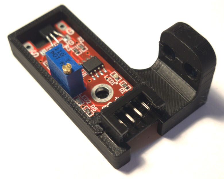
A Hall sensor is a sensor that can measure the strength or presence of a magnetic field as it deflects electrons creating a small voltage. In my final project, I used this sensor. By mounting a diametric magnet onto the end of the rotating shaft, the Hall sensor should measure the the angle of the rotation.
This sensor has four output pins, the analog output, ground, 5 V and a digital output. The latter only allows for information on the presence of a magnet. As I will need information of the strength of the magnetic field, I choose the analog output in addition to the ground and 5V connection.
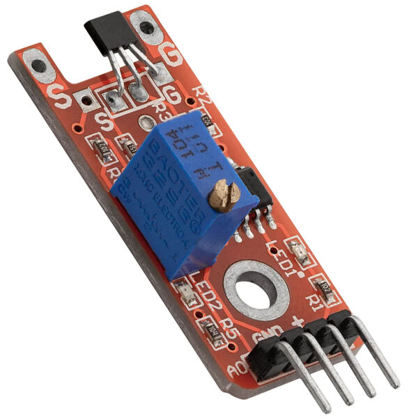
Breakout Board with Hall Sensor (Black Box in the Top)
After establishing a serial communication to the board, connecting the Hall sensor to it at the according pins and making sure this setup works properly, I simulated its operation by rotating the magnet with a motor. For this, I designed a magnet holder, that can be mounted on the end of a round shaft with a diameter of 10 mm.
Such a component can be seen in the image. Firstly, the magnet is inserted through the hole in the bottom and then it is mounted on the end of the shaft. A set screw on the side secures its position on the shaft and a set screw on the end fixes the magnet to the shaft to make it rotate with the shaft.

Magnet Holder
For simulating the operation in my final project, I mounted the magnet holder on the motor shaft. Next, I programmed my main board using a programmer board to rotate the motor and simultaneously read the value of the Hall sensor. The script can be seen here. The setup is shown in the image below.
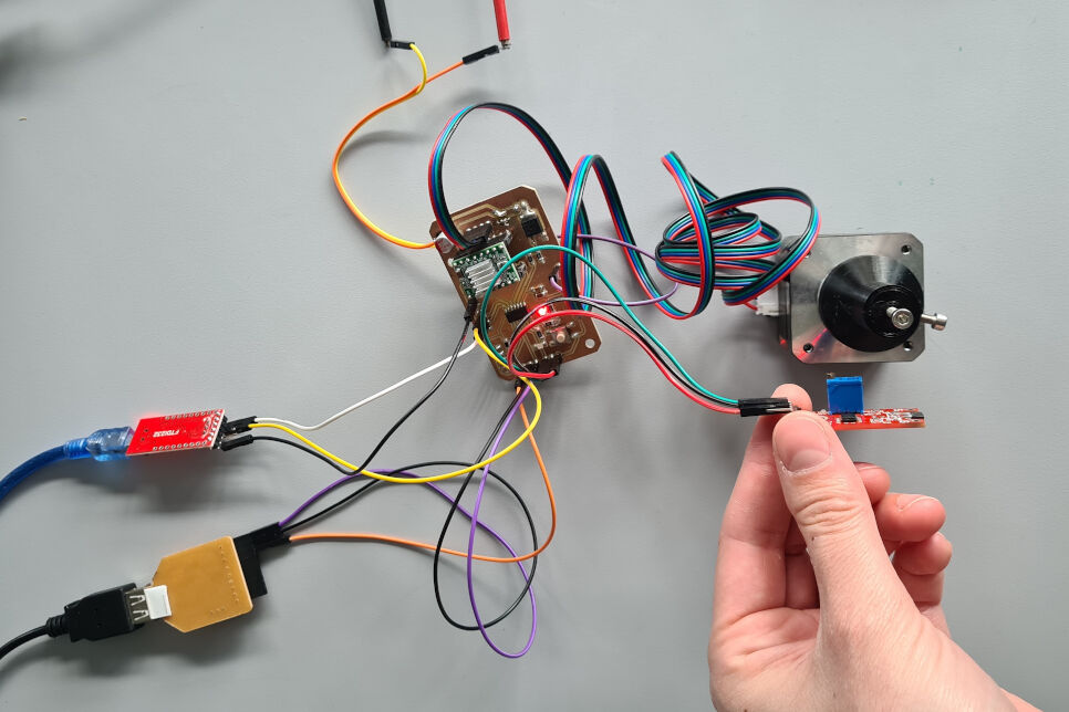
Setup for Angle Measurements
During the measurements, I tried to hold my hand as steady as possible to keep the Hall sensor in a constant distant to the magnet. I opened the serial plotter of the Arduino IDE via Tools > Serial Plotter which showed the sensor readings below. The deviations of the slope in the readings correspond to an off-centric rotation of the magnet as the magnet holder is designed for a 10 mm shaft and not the 5 mm shaft of the motor.
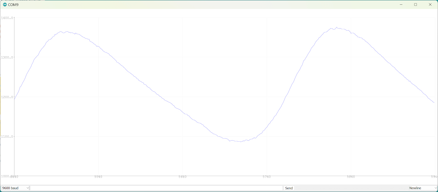
Results of Measuring the Angle of the Rotation
Recoding Videos
Recording videos using a Raspberry Pi camera can easily be done with a Python script and the "Picamera2" library. In addition to the very basic way of recording, the frame rate as well as the resolution of the video can be configured. Such a script can be seen below and in the according assignment.
from picamera2 import Picamera2
from picamera2.encoders import H264Encoder
from picamera2.outputs import FfmpegOutput
import time

duration = 2 # Duration of video recording in seconds

picam2 = Picamera2() # Create camera instance
video_config = picam2.create_video_configuration(main={"size": (1700, 1275)}) # Configure resolution
picam2.configure(video_config) # Add configurations to camera (with default 30fps)
h264encoder = H264Encoder() # Create encoder


picam2.start_recording(h264encoder, FfmpegOutput("video.mp4"))
print("Recording...")

time.sleep(duration) # Wait for a certain amount of time before stopping the recording

picam2.stop_recording() # Stop recording
print("Video recording has stopped!")
Upon running this script, it creates a video on the desktop which is 2 s long with the defined resolution and 30 frames per second.
Recording Videos
System Integration
In system integration, different sub-systems of a whole project are brought together. In my case, the two sub-systems are the mechanical and the electrical parts. The complete assignment and its details can be seen here.
The mechanical systems include the frame and the parts that are suspended by the frame. These are actually even two sub-systems of the mechanical parts which are joined by in total four ball bearings.
Components Suspended by the Frame

The Frame

Assembled Mechanical Parts
The electrical components consist in the core of a main board, that I made during the electronics design assignment bearing an AtTiny1614. There are two output devices, namely the stepper motor and the LED strip, as well as two input devices, the hall sensor and Raspberry Pi camera. Most of it is powered by the USB outlet of a computer. However, the motor and the LED strip are supplied with 24 V and the Raspberry Pi camera via its own power supply.
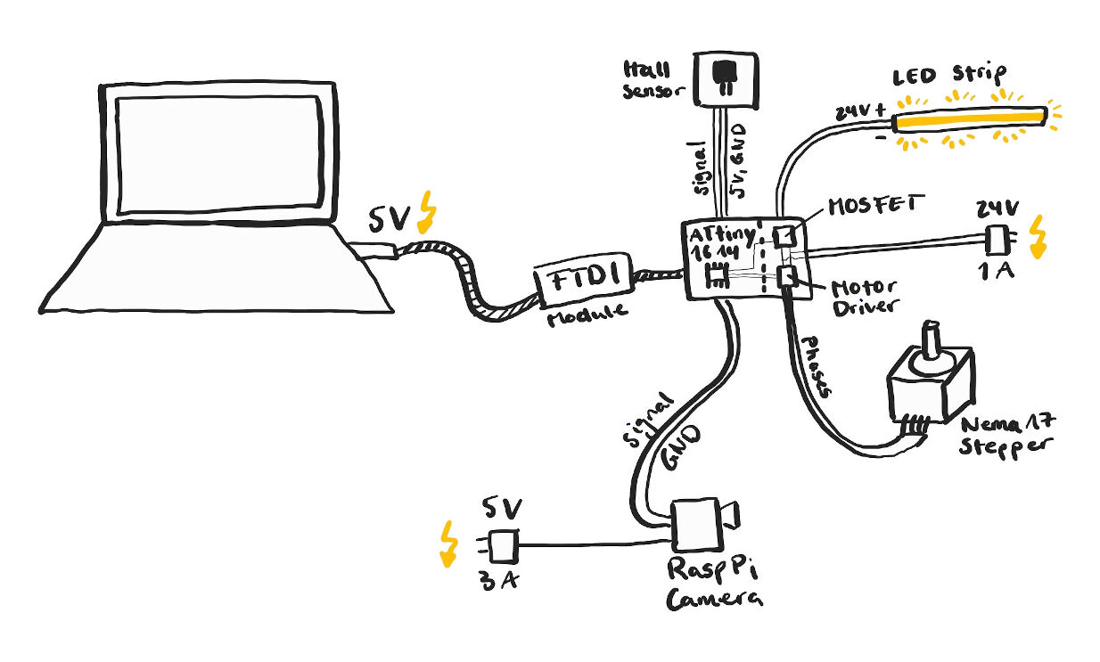
Electronic Components
To accomplish system integration successfully, three aspects have to be addressed, i.e. the attachment of the electronics parts to the mechanical parts, housings for the electronics parts and cable management by appropriate routing.
The first aspect, attachment of components was already incorporated in the 2D design. This is valid for the Raspberry Pi camera, the LED strip and the motor. The remaining components are attached via their housings.
Housings for Electronics
For the housings, I intended to use 3D printed JST connectors. After figuring out the best dimensions for an optimal fit of the female and male parts, I designed the housings including such connectors for the Hall sensor, the FTDI module and the main board. Additionally, a housing for the Raspberry Pi camera without a housing was designed.
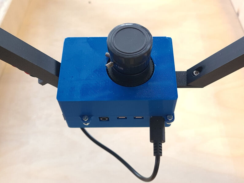
Raspberry Pi Camera with the Housing
Housing for the Hall Sensor
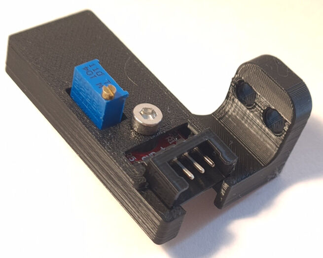
Housing for the Hall Sensor with Lid
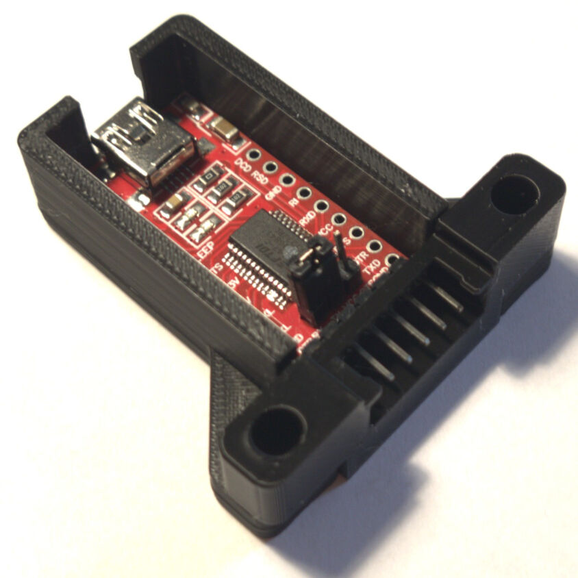
Housing of FTDI Module without Lid

Main Board on Bottom Half of the Housing
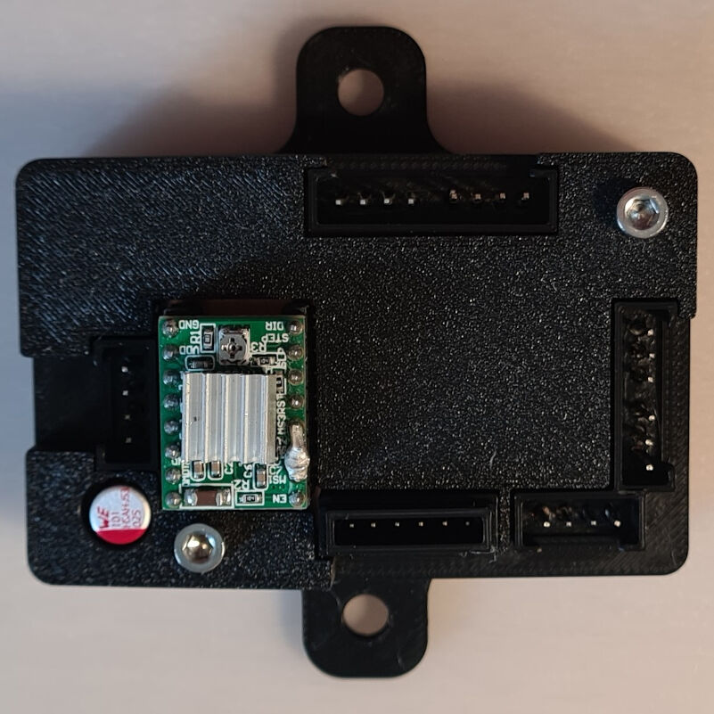
Complete Housing for Main Board
Cable Routing
In addition, the cable routing was addressed at three places, namely from the camera to the rotating platform, from the rotating platform to the frame, and along the frame. For the first, the mount for the camera already incorporated some clips to allow for the routing.
The second aspect was accomplished with a braided sleeve that allowed the cables to stay together and not disintegrate. Furthermore, this setup also allowed for a free rotation of the platform up to 180°.
Lastly, cable routing along the frame was improved by using "U"-shaped parts that can be mounted on the side of the material of the frame. By drilling a hole such that a bolt can be inserted through the frame and the cable routing part, the cables can be fixed at a designated position.
If you look closely, all of the cable routings for all three places can be seen in the images below.
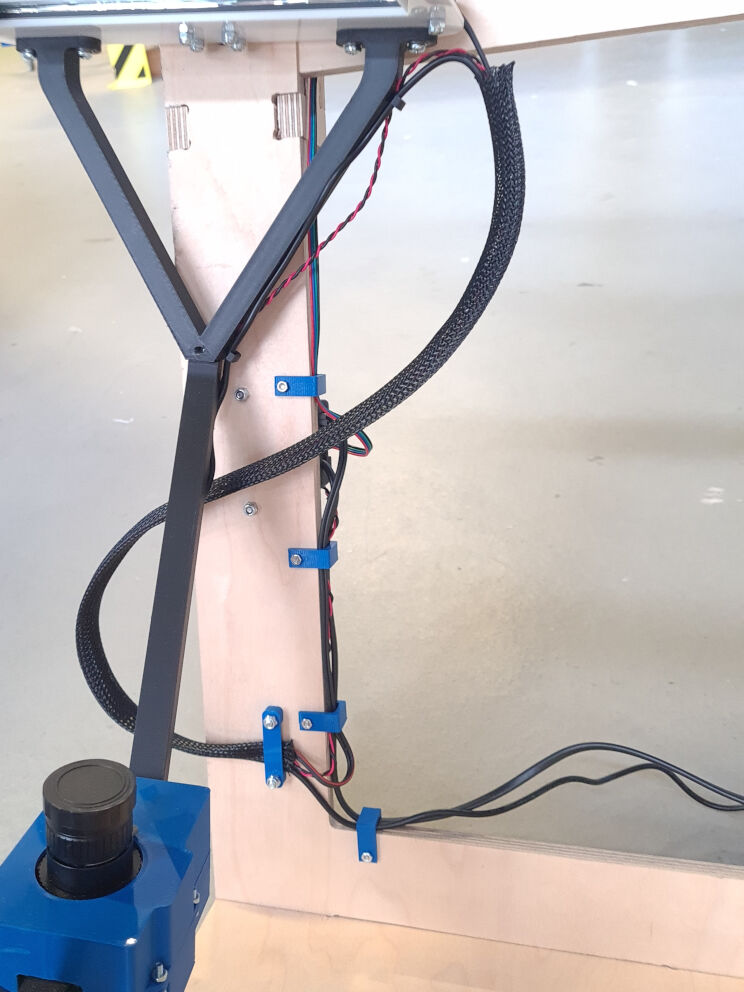
Sleeve with Cables in 5° Position of the Platform
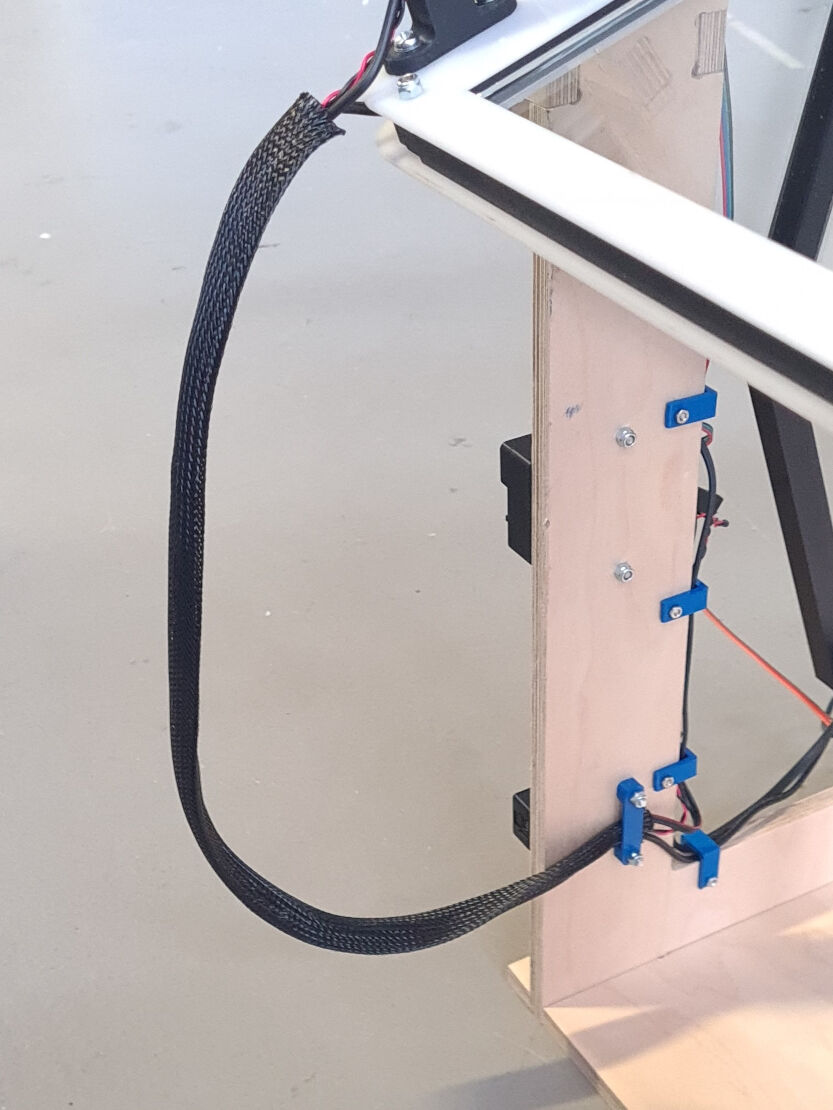
Sleeve with Cables in 160° Position of the Platform
Interface & Application Programming
During the assignment on interface and application programming, I programmed a graphical user interface (GUI) in Python using the package Tkinter and an advanced version of this package called CustomTkinter. However, before starting to program, it is always good to have an idea of what to program. Then, the idea can be put into action by programming the GUI, giving it functionality and lastly programming also the main board and the Raspberry Pi camera to react accordingly.
Functional Diagram
Basically, the program should run on a laptop that is connected to a main board via an FTDI module using the UART communication protocol. After the user was able to locate the right device with the COM ports, different input choices can be made.
All of these choices and inputs are then put into action upon pressing the START button. Firstly, the brightness is transmitted to the main board which will adapt the PWM signal for controlling the brightness of the LED strip via a MOSFET accordingly.
Furthermore, the video recording is started. The message "START" is send to the main board which sets the signal pin connected to the Raspberry Pi camera to a high voltage level. For more details on how this induces video recording, please see either the summary on this page or the complete development of this function in the according weekly assignment.
Next, one of either loops is entered depending on the selected mode. In case it is static, nothing happens until either the STOP button is pressed or the input of the end duration is reached. For the dynamic mode, steps are send to the main board which are then performed. This is repeated in a frequency of 30 Hz until either the STOP button is pressed or the end angle is reached.
Lastly, the video recording is stopped, which happens analogously to the start of the recordings.
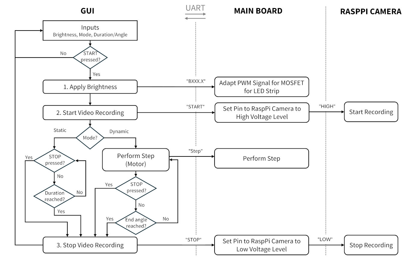
Functional Diagram
In this version of the GUI, the Hall sensor is not yet included. Therefore, I added one aspect, namely after performing a step the main board should read the Hall sensors output and send this to the connected computer via the UART communication. The computer then temporarily stores the values in e.g. a list. Once, the measurements are terminated, either by pressing the STOP button or by reaching the end angle, the user is asked to specify a folder path about where the readings should be stored via a file dialog.
After that, the previous functional diagram is valid again and proceeds with stopping the video recordings. The communication to the main board and the Raspberry Pi about terminating the recording is not shown in the appended functional diagram.
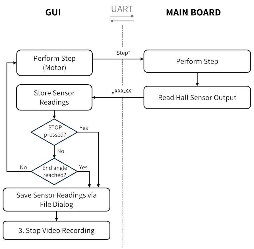
Appended Functional Diagram
Programming a Graphical User Interface
After I sketched how I would like the GUI to look, I started programming the window and filled it with content. From the first example program on the website of CustomTkinter and a Tkinter tutorial, I got to know how to program a single window.
import customtkinter as ctk

class App(ctk.CTk):

	def __init__(self, ):
		super().__init__()

		self.geometry("300x50") # Set the width and height of the window
		self.title("Rotating FTIR Platform") # Set title of window
		self.title = ctk.CTkLabel(self, text = "Rotating FTIR Platform") # Create a label
		self.title.pack() # Displays the title in the window

app = App()
app.mainloop() # Window is now reactive (starts to listen to events)
When executing this program in VS code, a window appears (see image).
It consists of a title in the top bar and a label in the middle of the window showing
the text "Rotating FTIR Platform". Next, I added the four frames to the window by
creating four CTkFrame instances.
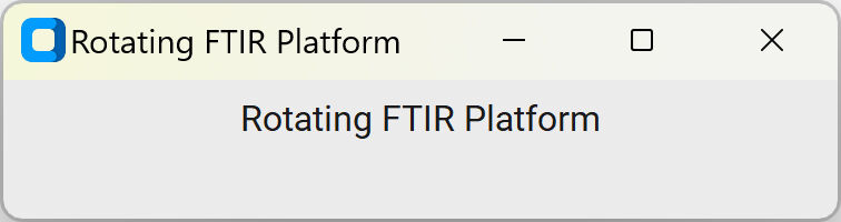
Window Created with CustomTkinter
I generated four frame in this window which can be positioned with the grid() function.
In the top, the frame contains control about the COM port selection to establish a serial connection. This is
actually done with a small message between the selected device, ideally the main board, and the computer. Upon
clicking on "Check Port", the message "Echo" is send to the device. If it is the main board, the anser "Echo: Echo" should
be received as it will be programmed to do so.
In the left, the brightness can be adapted with a slider and applied with another button. On the right, the mode can be selected and the input parameter can be given. In the bottom, the user can press START and STOP and has a feedback on how long the experiment has been running since pressing START. Below, you can see the outcome of the programming. Details on this are shown in the according assignment.
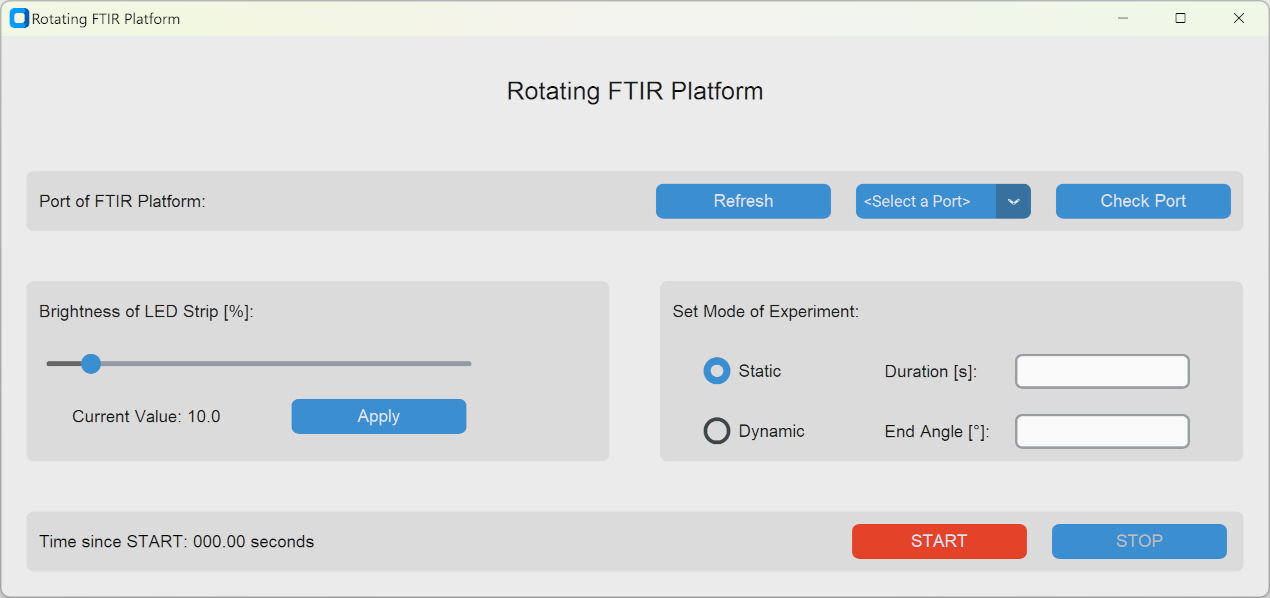
Complete GUI
In addition to this version of the GUI, I needed to add the Hall sensor and it intended use as shown in the appended functional diagram. For this, I had to first of all add the import for the filedialog and initialize an array where the data of the angle can be stored together with the timestamp upon receiving.
import tkinter.filedialog as filedialog
import numpy as np

class App(ctk.CTk):

def __init__(self, ):
	super().__init__()
	self.angle_data = np.array([['Time', 'Raw Angle']], dtype = str)
Next, I had to adapt the function which sends the message "Step" to the main board. Instead of only using a one-way communication, the program waits for a reply after sending the "Step" message. It takes the time and stores both in the array by appending it.
Once, the thread should stop, i.e. if the self.stop variable is True, the filedialog
pops up and asks the user for a folder path. In case no path is entered, this information is displayed and it is asked
for confirmation. Here, the user is able to go back and enter a folder path or dismiss it and loose the data.
When saving the data, the information of the array is stored in a .csv file at the destination and the array is reset.
The code for this is shown below. The complete Python script for the gui can be found in the downloads.
# Send "Step" to the board such that it performs a step
self.ser.write(str.encode("Step"))

# Get the reading of the angle measurement
curr_time = datetime.now()
angle_time = curr_time.strftime('%H:%M:%S.%f')
angle = self.ser.readline().decode().rstrip("\r\n")
self.angle_data = np.append(self.angle_data, np.array([[angle_time, angle]]), axis = 0)

# If the stop button was pressed
if self.stop == True:
	file_path = ''
	while file_path == '':
		file_path = filedialog.asksaveasfilename(defaultextension='.csv', filetypes=(("CSV File", "*.csv"),("All Files", "*.*") ), initialdir='.',title ="Select a Folder to Save the Angle Measurements")
		if file_path == '':
			if messagebox.askyesno("Do not save", "You have not selected a destination folder to save the angle measurements. Are you sure you do not want save them? You cannot go back!"):
				file_path = 'Cancel'

	if file_path != 'Cancel':
		# Create the CSV file and write to it
		with open(file_path, 'w', newline='') as myFile:
			writer = csv.writer(myFile)
			for unit in self.angle_data:
				writer.writerow(unit)

	self.angle_data = np.array([['Time', 'Raw Angle']], dtype = str)
	break
Embedded Programming of the Main Board
As presented above, the microcontroller must be able to react to the messages "BXXX.X", "START", "Step", "STOP" and also "Echo" appropriately. To do this, I programmed the main board using the Arduino IDE via a programmer board. Details on the connections and on how to program this board can be found here.
The script for the main board start with some declarations of pins and a setup function including the initialization of the serial communication. The loop however is the interesting part. In this case, it simply waits until it receives a message and echos it by adding "Echo: " in front of it. With this, the GUI also gets feedback that the sending was successful. Based on the characters of the received message, the according code blocks are executed to initiate the functions shown in the functional diagram above. For the complete code and details on the development, please see here.
As I later added the function that the readings of the Hall sensor are send to the computer after each step, I had to address that as well. In contrast to simply echoing every message, the adapted Arduino sketch now recognizes the "Step" message and returns the Hall sensor readings averaged over five measurements. Then, the remaining incoming messages are handled as previously shown in the according assignment. The new code snippet is shown below. The complete Arduino sketch for the main board can be found in the downloads.
if (msg != ""){
	if (msg.startsWith("Step")){
		// Perform a step by generating a single pulse
		digitalWrite(stepPin,HIGH);
		delayMicroseconds(200);
		digitalWrite(stepPin,LOW);
		delayMicroseconds(200);
		angle = 0.0;
		for (int i = 0; i < 5; i++){
			angle = angle + (float) analogRead(hallPin);
		}
		Serial.println(angle/5);
	}
	else{
		// Handle other messages and echo them
	}
}
Programming the Camera
As shown above, recording videos is relatively easy. However, the recording of videos should start upon a trigger and stop upon another one. As the cables from the main board to the Raspberry Pi will be relatively long, I decided against a communication protocol like I2C but instead only used a digital signal in the form of a high voltage level for recording and a low voltage for no recording. An according script can be seen in this section.
To develop such a script, I firstly wrote a Python script that sensed the digital voltage level of an GPIO. Then, I manually connected the chosen signal pin (GPIO number 11) to the 5 V pin and ground pin, alternatingly, via jumper cables. In the video, you can see the change of voltage level with the jumpers while the sensed voltage level is shown in the output.
Sensing the Voltage Levels
Once, this was working, I merged it with the basic video recording script. This resulted in a new video every time the 5 V pin was connected to the pin 11 and the end of the video when it was disconnected and connected to the ground pin.
Start and Stop of Recording is Controlled with the Voltage Levels
In addition to this, I had to run the script automatically after the Raspberry Pi is booted without starting it manually.
For this, I found a tutorial
that I followed. The method in there edits the rc.local file by appending a terminal command to it that executes
the python script. To do this, I opened a terminal and typed in the following line.
sudo nano /etc/rc.localThis opened an editor in the terminal. In the bottom of the file, I added another line shown below.
sudo python /home/blackberry/Desktop/FTIR_video_recording.py &With this, the Python script with the specified name and at the defined location is executed.
Lastly, I had to set the focus and aperture. For this, the camera lens has two adjustment rings that can be turned and fixed in position with set screws. Here, I basically followed the file from Raspberry on how to mount the lens. In addition, I used a live view of the camera shown with the script below which I obtained from here.
import time
from picamera2 import Picamera2

picam2 = Picamera2() # Create camera instance
config = picam2.create_preview_configuration() # Create preview configurations
picam2.configure(config) # Set the configurations
picam2.start(show_preview=True) # Start the preview
time.sleep(2) # Update image
image = picam2.capture_array()
With the live view, I firstly opened the aperture completely, then turned the ring for the focus to the right positions until I found the right focus and fixed its position with the set screw. I repeated the process for the aperture. Below, you can see how the aperture opens and closes. Please not, that the ring turns close to 360° from a fully closed to a half-way opened and to a almost fully closed aperture.
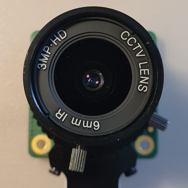
Aperture Fully Opened
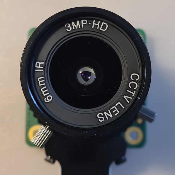
Aperture Half-Way Opened
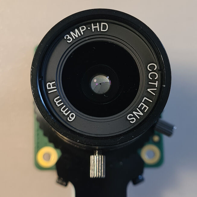
Aperture Almost Fully Closed
Final Project Presentation
In the end, every student has to present their own final project. As they were recorded and published, you can see my presentation here. It starts at about 1:18:55. Below, you can see the slide and the video that I used for presenting.
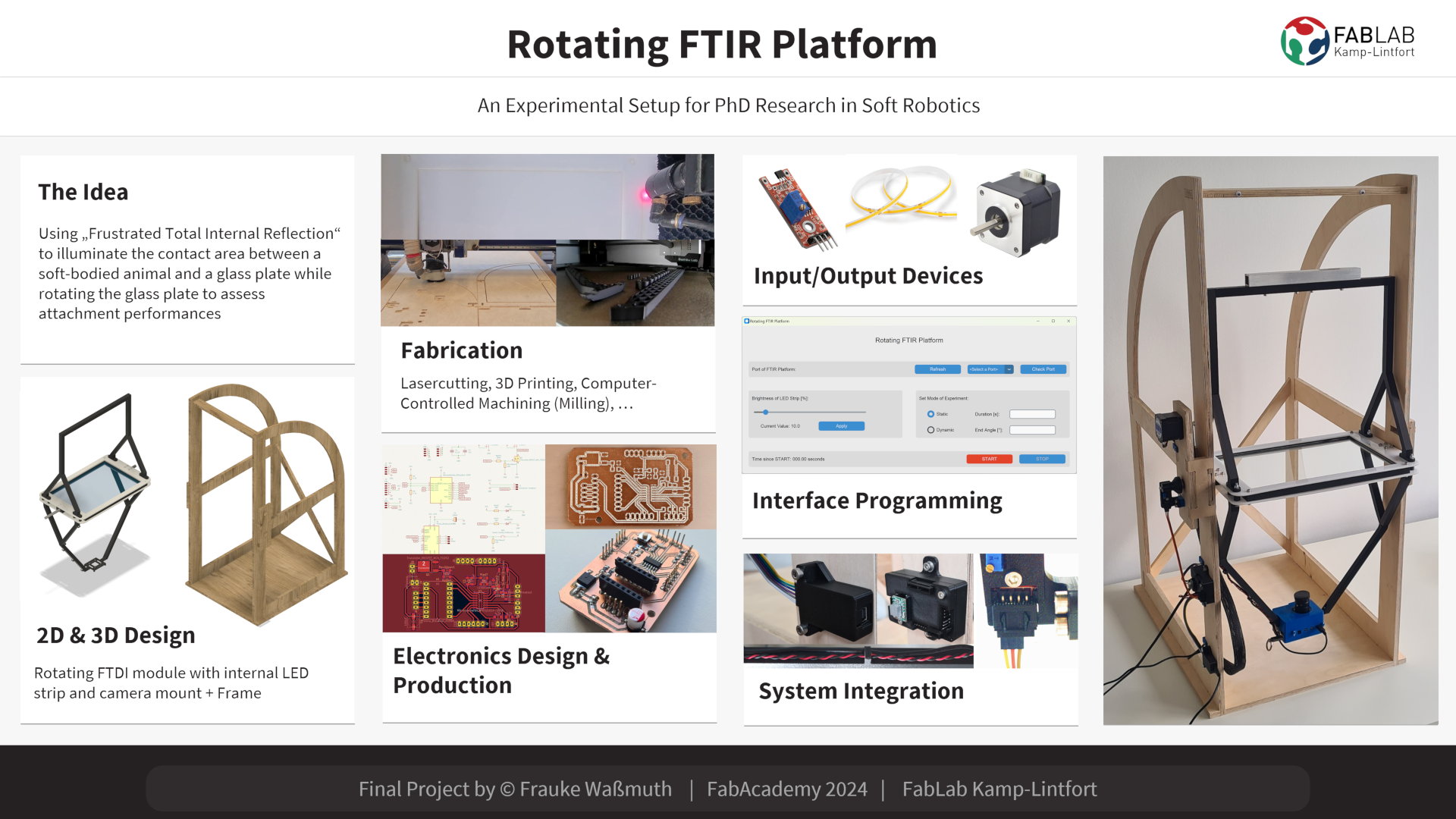
Summary Slide
Video Clip
Design Files and Source Code for Download
Project Management
- Bill of Materials (.xlsx): List of materials and components split into "Making", "Buying" and "Electrical" showing the needed quantity, source, the costs and for materials also the fabrication process
CAD of Mechanical Parts
- CAD of Parts Suspended by the Frame (.f3d): CAD of all Parts suspended by the frame including the glass plate, LED strip profiles, lasercut frames, their spacers, shaft mount halves, the camera mount and the counterweight mount
- CAD of Frame (.f3d): CAD and CAM of the frame for my final project
CAD of Electrical Parts
- Schematic Design (.kicad_sch): KiCAD file including the logics and schematics of the PCB
- PCB Layout (.kicad_pcb): KiCAD file for physical layout of the PCB
- Project (.kicad_pro): KiCAD project file
System Integration Parts
- JST Connectors (.f3d): 3D printable JST connectors in male and female version for three, four and six pins
- Housing for Raspberry Pi Camera (.f3d): Two halves of the housing to enclose the Raspberry Pi board, camera module and lense
- Housing for Hall Sensor (.f3d): Housing and attachment to the frame for the hall sensor
- Housing for FTDI Module (.f3d): All parts assembled for the housing of the FTDI module
- Bottom Part of Housing for Main Board (.f3d): Bottom half of the housing for the main board
- Top Parts of Housing for Main Board (.f3d): Parts for the housing of the main board on top of the board including the JST connector parts and cover as well as customized female JST connectors
- Cable Routing (.f3d): Part for attachment of sleeve to frame and cable routing parts along side of the frame
Source Code for Interface & Application Programming
- Graphical User Interface (.py): GUI for communication with the main board allowing the input of required variables
- Arduino Sketch for Main Board (.ino): Arduino Sketch responding to messages received via serial communication to rotate a motor or apply the brightness to the LED strip
- Video Recording Script for Raspberry Pi Camera(.py): Merge of the video recording script with sensing the digital input of the GPIO pin number 11 with additional functionality
Project Presentation
- Summary Slide (.png): Slide summarizing my final project for the presentation
- Video Clip (.mp4): Video summarizing my final project for the presentation
License
Rotating FTIR Platform
by
Frauke Waßmuth is licensed under
CC BY-NC-SA 4.0
![]()
![]()
![]()
![]()