14 - Interface & Application Programming
A GUI for My Final Project
This week is the programming-heaviest week as I would say. However, I am really into programming and have many experiences. My favorite language so far is Python even though I have not implemented any graphical user interface (GUI) except for some diagrams with it so far. For this, I so far only have used Java and Processing.
This week was, as you might guess from the title and my description about programming a GUI. However, the purpose of it is to interact with a board that does something if the GUI is presented a certain input like pressing a button. In detail, this weeks's assignment were:
- Group Assignment
- Compare as many tool options as possible
- Individual Assignment
- Write an application that interfaces a user with an input &/or output device that you made
Group Assignment
The group assignment was to compare different tool options. The tool options here are different frameworks witch which an application or an interface can be programmed. In general, almost endless tools exists and it appears difficult to pick one of these. However, many are outdated or not easy to use and so on. During the global lecture, my fab mates and I got presented a more restricted selection of tools which are the currently the best ones available.
They can be sorted into the language they are using or are based on. For Python, the three most popular frameworks are Tkinter, wxPython and PyQt. For interfacing output or input devices via an Arduino, the potentially most popular framework is Processing as it was developed for the use with Arduino boards. Its language is unique but based on Java. Other tools are for example Flutter or the MIT App Inventor. For more details on the frameworks and a comparison of them, please refer to our group page.
In total however, either Processing or
Individual Assignment
For the individual assignment, I decided on designing and programming a graphical user interface (GUI) for my final project to control everything from my computer and communicating with my final project board. As a programming language I decided to go with Python.
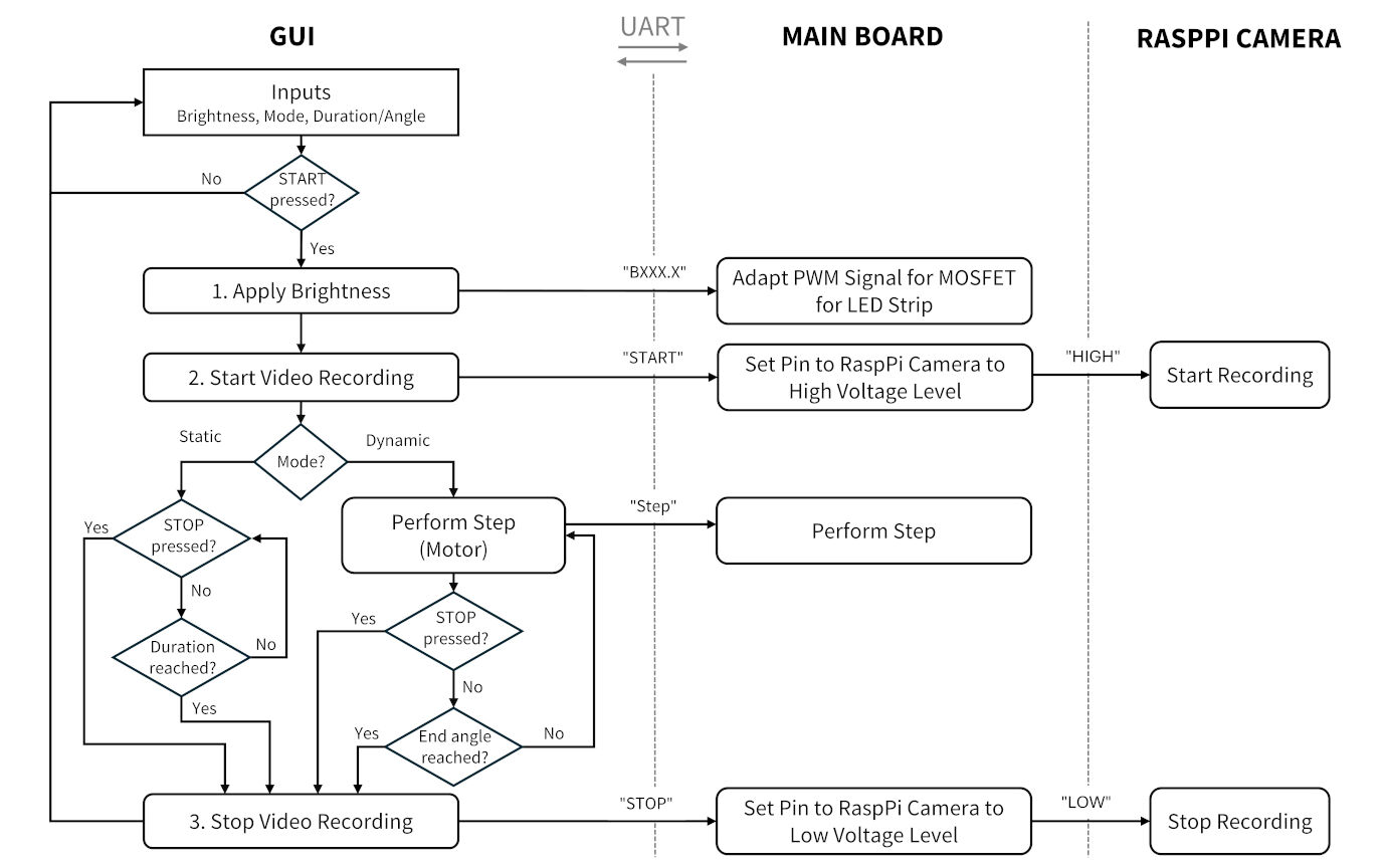
However, before I jumped into programming a GUI, I thought of how it should function and look like. For this, I drew a functional diagram as well as sketched my idea for the GUI with the four different frames and later programmed it starting with the top frame and proceeding with the left and right one while already implementing few basic functions. Later, for the last frame, I programmed the more advanced functions to allow for turning the motor and recording videos by sending specific serial commands. Lastly, I programmed the Arduino and the reactions to the serial commands it receives from the host computer.
Functional Diagram of the Interfaces
Basically, the program should run on a laptop that is connected to a main board via an FTDI module using the UART communication protocol. After the user was able to locate the right device with the COM ports, different input choices can be made. These are the brightness of the LED, the mode of the experiments and a START and STOP button. The mode of the experiments comes with another input, which are for the static mode where no rotation happens the duration of the recording and for the dynamic mode the end angle of the rotation.
All of these choices and inputs are then put into action upon pressing START. Firstly, the brightness is transmitted to the main board via a message starting with B followed by the percentage of the brightness in the format of XXX.X. The main board then recognizes that the brightness should be adapted and extracts the value. The PWM signal controlling the MOSFET is lastly adapted accordingly.
Furthermore, the video recording is started. After the brightness adaption was communicated, the message "START" is send to the main board. When receiving this message, the main board simply sets the signal pin connected to the Raspberry Pi camera to a high voltage level. For more details on how this induces video recording, please see either the summary on this page or the complete development of this function in the according weekly assignment.
Next, one of either loops is entered depending on the selected mode. In case it is static, nothing happens until either the STOP button is pressed or the input of the end duration is reached. For the dynamic mode, steps are send to the main board which are then performed. This is repeated in a frequency of 30 Hz until either the STOP button is pressed or the end angle is reached.
Lastly, the video recording is stopped, which happens analogously to the start of the recordings.
Sketch of the Graphical User Interface
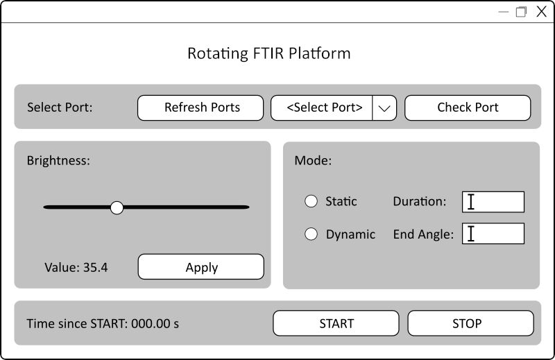
Before I started sketching, I tried to determine what I will need to control. First of all, I will need to generate a serial connection to the board. Furthermore, I would like to be able to adjust the brightness of the LED strip. Next, the user should have a choice of the mode, i.e. a static mode in which videos are recorded while the platform does not rotate and a dynamic mode in which the platform rotates during recordings. Lastly, a start and stop control should be added.
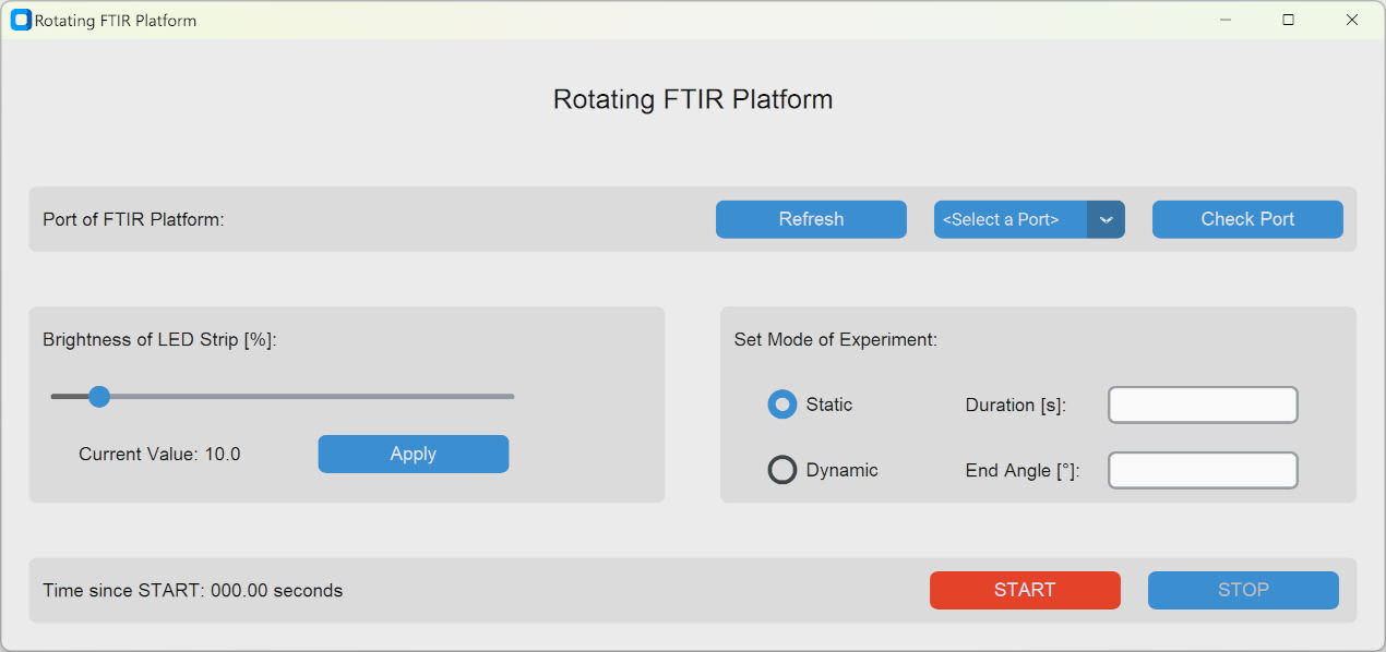
With this in mind, I sketched a GUI as shown on the side in Inkscape It consists of a title and below it of four different regions or frames indicated with the grey color that allow the user to control either the serial connection in the top frame, the brightness of the LED strip in the left frame, the mode in the right frame and lastly the start and stop of the measurements in the bottom frame.
The top frame concerns the serial connection. Here, the user should select a port which is supplied in a dropdown menu. However, the port should be checked in case the wrong one was selected. Lastly, the dropdown showing the available ports should be refreshed in case the connection was lost or the board was detached.
The left frame allows the user to adjust the brightness of the LED strip. Here, a slider widget should be present that adjusts the brightness between 0 % and 100%. Below, the value of the current position of the slider should be displayed. Next to it, an "Apply" button is positioned to apply the value set by the user to the LED strip.
In the right frame, the mode can be set. In case the static mode is selected, an input about the total recording time should be given. In case it is missing, the duration is undefined and the recording can only be stopped by pressing the STOP button. The dynamic mode similarly requires the input of an angle to which the platform should rotate.
The bottom frame should display the time since when the START button was pressed. A STOP button should terminate the recordings and movements of the platform.
Programming the Graphical User Interface in Python
There are many ways of programming a GUI. However, I read a couple of rankings of the frameworks which can be used with Python. Here, I found this ranking which puts PyQT in the first, Tkinter in second and wxPython in third place. Here, I decided to go for Tkinter as it does not require any additional packages, is free to use and is already implemented in the (newer) python versions.
Due to previous experiences with Python, I already had setup Python 3.10 on my computer and had the programming IDE VS Code already configured for using it. Therefore, I simply created a .py file and opened it in VS Code. Next, I started to look for tutorials on how to create a GUI with Tkinter. Here, I came across the UI-library CustomTkinter which is based on Tkinter. The default settings of the widget looked quite beautiful and therefore I continued using it.
From the first example program on the website of CustomTkinter and a Tkinter tutorial, I got to know how to program a single window. I used that knowledge together with object-oriented programming, a good practice for programming, and created the following code.
import customtkinter as ctk

class App(ctk.CTk):

	def __init__(self, ):
		super().__init__()

		self.geometry("300x50") # Set the width and height of the window
		self.title("Rotating FTIR Platform") # Set title of window
		self.title = ctk.CTkLabel(self, text = "Rotating FTIR Platform") # Create a label
		self.title.pack() # Displays the title in the window

app = App()
app.mainloop() # Window is now reactive (starts to listen to events)
When executing this program in VS code, a window appears (see image).
It consists of a title in the top bar and a label in the middle of the window showing
the text "Rotating FTIR Platform". Next, I added the four frames to the window by
creating four CTkFrame instances.
To position the frames, I replaced the .pack() function with the
.grid(row = , column = ) function which
allows me to position the widgets in a grid by specifying the row and column inside the function.
Additionally, the arguments columnspan and rowspan can be used in case
the widget should span multiple columns or rows, respectively. The code and the respective
widgets and their placements using the .grid() function is shown below.
import customtkinter as ctk

class App(ctk.CTk):

	def __init__(self, ):
		super().__init__()

		self.title("Rotating FTIR Platform") # Set title of window

		############################### Title
		self.title = ctk.CTkLabel(master = self, text = "Rotating FTIR Platform")
		self.title.grid(row = 1,column = 1, columnspan = 6)

		############################### Top: Port input
		top_widget = ctk.CTkFrame(master = self)  # Top: Serial communication via port
		top_widget.grid(row = 2, column = 1, columnspan = 6)

		############################### Left: Set brightness
		left_widget = ctk.CTkFrame(master = self)  # Left: Adjust Brightness
		left_widget.grid(row = 3, column = 1, columnspan = 3, rowspan = 3)

		############################### Right: Set Modes and their properties
		right_widget = ctk.CTkFrame(master = self)
		right_widget.grid(row = 3, column = 4, columnspan = 3, rowspan = 3)

		############################### Bottom: Start and stop with timer
		bottom_widget = ctk.CTkFrame(master = self)
		bottom_widget.grid(row = 6, column = 1, columnspan = 6)

app = App()
app.mainloop() # Window is now reactive (starts to listen to events)
As you can see in the image, the frames do not really have and shape and are not positioned as expected. This is due to the fact, that they do not contain anything and by this have a default, rectangular shape.
Nevertheless, the general positioning of the frames is correct as one is in the top, one is in the bottom and then two are placed in the middle next to each other.
In order to fill them with content, other widgets must be created. They can then be placed
inside of the frame by changing the argument master = selfmaster = top_widget
Below, you can see how I created the GUI I wanted and which steps I tool. Nevertheless, I won't show the complete code as it is quite comprehensive. Please refer to the download section for the complete source code.
Top Frame: Communication to the Board via a Serial Port
For the top frame, I simply started by adding a label, a button, an option menu, i.e.
a dropdown, and another button with their according text at their according position
specified with the column argument of the .grid() function.
############################### Top: Port input
top_widget = ctk.CTkFrame(self)  # Top: Serial communication via port
top_widget.grid(row = 2, column = 1, columnspan = 6)

self.port_label = ctk.CTkLabel(master = top_widget, text = "Port of FTIR Platform:")
self.port_label.grid(row = 0, column = 0)

self.refresh_ports = ctk.CTkButton(master = top_widget, text="Refresh")
self.refresh_ports.grid(row = 0,column = 1)

self.port_option = ctk.CTkOptionMenu(master = top_widget)
self.port_option.grid(row = 0, column = 2)

self.check_port = ctk.CTkButton(master = top_widget, text="Check Port")
self.check_port.grid(row = 0,column = 3)
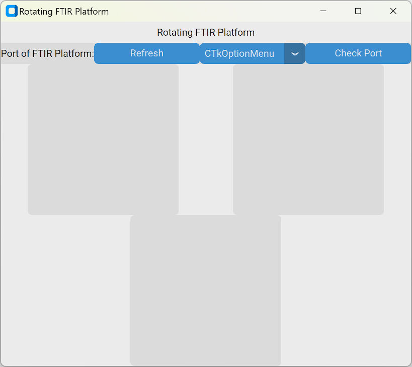
This generates a window as shown in the image. The shape of the top frame has changed and it is filled with content. However, this window is not at all responsive and nothing happens when a button is pressed. Even the dropdown does not show any list of which the user can choose a port.
In order to add functionality,
the command argument must be added to the refresh and the check port button. For the option menu
this process is slightly more difficult.
E.g. for the refresh button the line of code where it is initialized can look like the following:
self.refresh_ports = ctk.CTkButton(master = top_widget, text="Refresh", command = self.refresh_ports)
This command references a function that must be defined inside the App() object as well. It could e.g.
look like the following.
def refresh_ports(self):
	""" Refreshes the option menu where the user can select the port """
	print("Refresh button pressed")
With this function, the string "Refresh button pressed" is printed into the terminal of VS code every time the refresh button was pressed. Such a method can also be applied to the check port button.
For the option menu, the process is slighly different. Here, the argument
values = self.options_portself.options_port. Then, a variable of the type
StringVar is passed to the option menu with the argument variable. Anytime the user selects
something from the dropdown, the selection is stored in this variable. Lastly, a function is passed to the option
menu also with the command argument. This is how the code looks for the top widget:
self.optionmenu_ports = ctk.StringVar(value="<Select a Port>")  # set initial value in option menu
self.options_port = get_serial_ports() # get all serial ports
self.port_option = ctk.CTkOptionMenu(master = top_widget,
		values = self.options_port,
		variable = self.optionmenu_ports,
		command = self.set_port)
self.port_option.grid(row = 0, column = 2)
As you can see, the values for the list for the dropdown is aquired with the get_serial_ports()
function. With this function, the serial ports are returned. To do this, I looked online and found a comment
in a forum on stackoverflow. The code worked for me so
I used it with some minor changes in my own code. This is the function.
def get_serial_ports():
	"""Returns a list of all ports available for this computer

	Returns:
		list: available ports
	"""
	from serial.tools.list_ports import comports

	ports = []
	for port in comports():
		ports.append(port.device)
	return ports
However, I had not yet talked about how the serial connection is achieved. For this, I firstly had to create
an instance of the Serial object of the
pySerial package in the __init__()
function of the App() object.
# Initialize serial communication
self.ser = serial.Serial(timeout = 2, write_timeout = 2) # Create instance and set the timeouts
self.ser.baudrate = 115200 # Set the baudrate of the communication
self.ser.port = "Undefined" # Set the port to undefined
self.checked_port = False  # Port was not checked
Then, the first serial connection is tried to be achieved when the selected port is checked. Here, the
self.check_port
tk.messagebox.showinfo(title="Information",
	message = "This port is not available. Please select a different port!")
However, if the serial connection can be opened, it sends a string "Echo" via the connection and waits for a reply of the connected port. If it is an echo of the previous message, i.e. if it is "Echo: Echo", the connection is a success. With opening and closing the serial communication, sending and receiving a string looks like this:
self.ser.open()
self.ser.write(str.encode('Echo')) # Send a message
msg = self.ser.readline().decode().rstrip("\r\n") # Receive a message
# Check if received message was the expected echo
if msg == "Echo: Echo": # Success
	# If the echo was received, make the "Check Port" button green and disable it
	self.check_port.configure(state = "disabled",fg_color = "#4eb82c")
	self.checked_port = True # Set the boolean to True that the port was successfully checked
self.ser.close() # Close the port
Here, it must be noted, that I programmed my board to reply with an echo of the received message. For this, I used the following Arduino script:
String msg;

void setup() {
	Serial.begin(115200); // Start serial communication
	while (!Serial); // Wait until Serial is open
}

void loop() {
	while (Serial.available()) { # Read a line
		delay(3);  //delay to allow buffer to fill
		if (Serial.available() > 0) {
			char c = Serial.read();  //gets one byte from serial buffer
			msg += c; //makes the string readString
		}
	}
	if (msg != ""){
		Serial.println("Echo: " + msg); // Print an echo
		msg = ""; # Reset the received message
	}
}
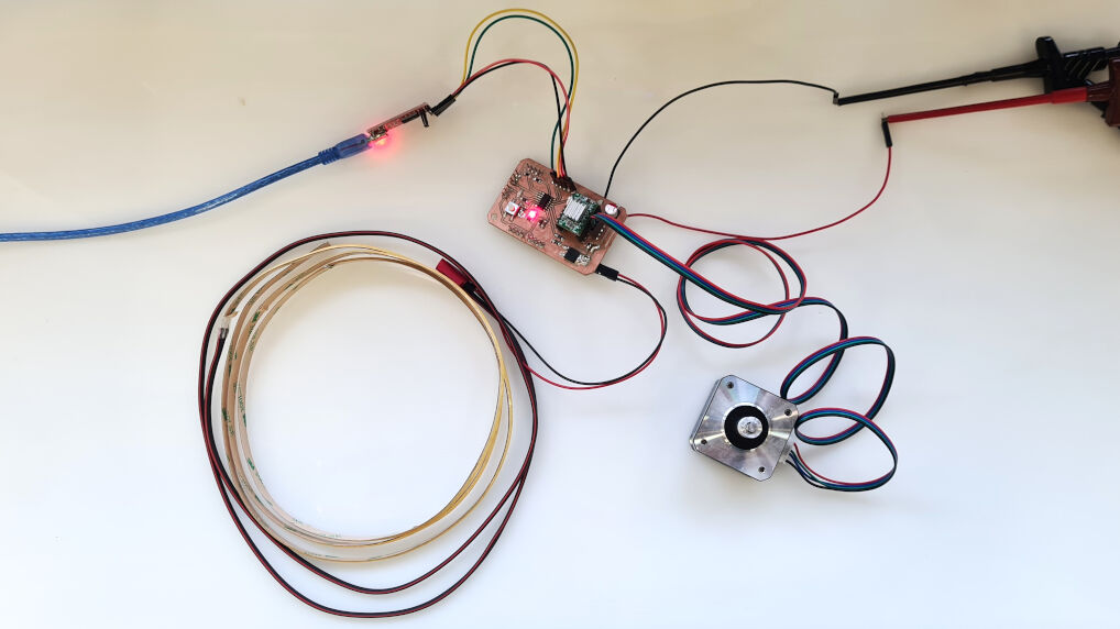
I programmed the board with a programmer board and after this connected it to my computer via an FTIR module as shown here. This allowed me to check the ports not only if they are available but also if it is the right port with the board that I created (and programmed).
Lastly, the refresh function was easily implemented by simply calling the get_serial_port()
def refresh_ports(self):
	""" Refreshes the option menu where the user can select the port """

	self.port_option.configure(values = get_serial_ports()) # refreshes list
	self.optionmenu_ports.set("<Select a Port>") # sets the text in the option menu
	self.ser.port == "Undefined" # Reset the current port
	self.checked_port = False # Set that the current port is not checked
	# Enables the "Check Port" button and undoes it being green
	self.check_port.configure(state = "normal",fg_color = blue_theme)
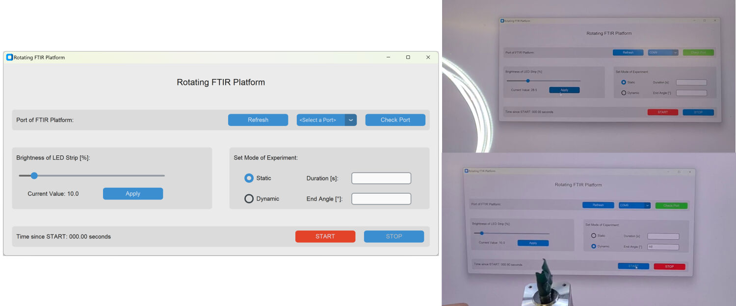
In total, I achieved the behavior shown in the video. Here, I had the board already connected to my computer and therefore checking the port was exited with a success shown with the green button. Refreshing the list of ports resets everything and displays the updated list of ports which is in this case identical to the first list.
Top Frame with Added Functions
Left Frame: Setting the Brightness of the LED Strip
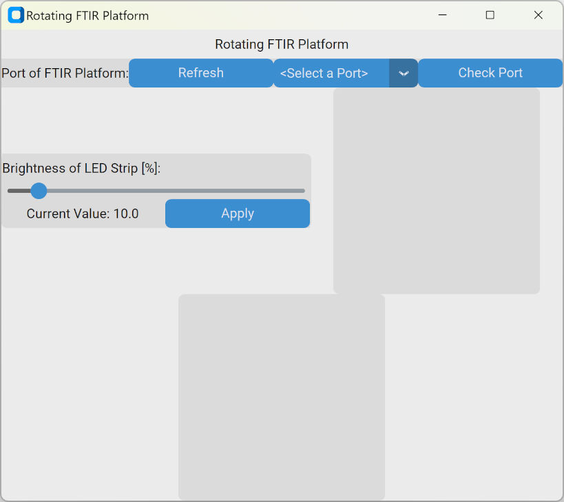
After the top frame was done and functional, I concentrated on the left frame where the user should be able to apply set the brightness of the LED strip by adjusting a slider. The value should be displayed in the bottom of the frame next to the "Apply" button which can be used to apply the brightness to the LED stip.
The first step here was again to simply add the labels and buttons. For the slider, I chose the
CTkSlider widget with a scale from zero to 100 with the unit percentage. Below, you
can see the widgets, their arguments and the positioning with the grid() function.
Left: Set brightness
	left_widget = ctk.CTkFrame(master = self)  # Create container on the left, contains brightness input
	left_widget.grid(row = 3, column = 1, columnspan = 3, rowspan = 3)

	self.led_label = ctk.CTkLabel(master = left_widget, text = "Brightness of LED Strip [%]:")
	self.led_label.grid(row = 1,column = 1)

	self.led_slider = ctk.CTkSlider(master = left_widget, from_ = 0, to = 100, width = 300)
	self.led_slider.grid(row = 2, column = 1, columnspan = 3)

	self.value_label = ctk.CTkLabel(master = left_widget,
		text = "Current Value: " + "") # Value to display is still missing
	self.value_label.grid(row = 3,column = 1, columnspan = 2)

	self.btn_apply_brightness = ctk.CTkButton(master = left_widget, text="Apply")
	self.btn_apply_brightness.grid(row = 3, column = 3)
Once the layout and labelling was done, I proceeded with implementing functionality. For the slider
I started by adding the argument variable where I inserted a newly created variable of
the type ctk.DoubleVar(), namely self.brightness. In the brackets of the
variable type, I furthermore specified the initial value to 10 [%]. Then, I
added a function to the slider called self.display_brightness using the command
argument.
Below, the complete code for the slider is displayed that I programmed for my GUI.
self.brightness = tk.DoubleVar(None, 10) # Brightness of LED strip, default 10%
self.led_slider = ctk.CTkSlider(master = left_widget,
	from_ = 0, to = 100, width = 300, variable = self.brightness,command = self.display_brightness)
The function that is called by the slider then directly accesses the label where the value of the
brightness slider should be displayed. It configures the label by setting the text to a new value. Here,
the value of the self.brightness variable is accessed with the .get() function.
def display_brightness(self, _):
	""" Display the brightness but updating the text of a label"""
	self.value_label.configure(text = "Current Value: " + "{:.1f}".format(self.brightness.get()))
Similarly, I changed the initial text of the value displaying label by adding the value of the brightness with the following code:
self.value_label = ctk.CTkLabel(master = left_widget,
	text = "Current Value: " + "{:.1f}".format(self.brightness.get()))
Lastly, I added a function to the "Apply" button. Every time this button is pressed, it calls the
self.apply_brightness function implemented with this code:
self.btn_apply_brightness = ctk.CTkButton(master = left_widget, text="Apply", command = self.apply_brightness)Lastly, I had to define the called function which I did with the following code:
def apply_brightness(self):
	""" Apply the brightness by sending the value to the board"""

	msg = "B" + "{:.1f}".format(self.brightness.get()).zfill(5)
	self.ser.open()
	self.ser.write(str.encode(msg))
	self.ser.flush()
	self.ser.close()
This function basically sends the brightness via the serial port to the board in the format of a String starting with "B" followed by three digits and a single decimal. To make the board responsive to this message, I implemented some more code into the Arduino sketch echoing the received messages. First, I added the pin for the LED strip with
const int ledstripPin = 0;// the number of the LED strip pinFurthermore, I had to declare this pin as an output and set it to an initial value of zero meaning the LED strip is off with the following code:
void setup() {
pinMode(ledstripPin, OUTPUT); // initialize pin as outputs
analogWrite(ledstripPin, 0); // Start with LED strip turned off
}
Then, I added more code in the loop function which is executed in case the received string
starts with "B". It will then extract the value of the brightness as a substring from the received
message and sets the brightness of the LED strip with the analogWrite() function. The
details on that, I explored in the week on output devices. This is the code:
Serial.println("Echo: " + msg); // Print an echo
if (msg.startsWith("B")){
	brightness = msg.substring(1).toFloat();
	Serial.println(brightness);
	brightness_analog = (int)((255.0*brightness/100.0)+0.5);
	Serial.println(brightness_analog);
	analogWrite(ledstripPin, brightness_analog);
}
With this I had implemented the function that I wanted. Please refer to this section a video on how the application of the brightnesses to the LED strip.
Right Frame: Selecting the Mode of Recoding
In the right frame, the user should select the mode of recording. This can either be static
or dynamic, i.e. the platform does not rotate or does rotate during recording. For either of the
modes, additional inputs are required, namely the duration of the recording and the end angle to
with the platform should rotate, respectively. This can be done with another widget, that has not been
used so far, the CTkEntry. For the selection of wither modes, I used the
CTkRadioButton widget.
############################### Right: Set Modes and their properties
right_widget = ctk.CTkFrame(master = self)
right_widget.grid(row =3, column = 4, columnspan = 3, rowspan = 3)

self.mode_label = ctk.CTkLabel(master = right_widget, text = "Set Mode of Experiment:")
self.mode_label.grid(row=1,column=1)

# Create radiobutton, label and entry for static mode
self.rbtn_static = ctk.CTkRadioButton(master = right_widget, text= modes[0])
self.rbtn_static.grid(row=2,column=1)

self.static_end_label = ctk.CTkLabel(master = right_widget,text = "Duration [s]:")
self.static_end_label.grid(row=2,column=2)

self.static_end_entry = ctk.CTkEntry(master = right_widget)
self.static_end_entry.grid(row=2,column=3)

# Create radiobutton, label and entry for dynamic mode
self.rbtn_dynamic = ctk.CTkRadioButton(master = right_widget, text=modes[1])
self.rbtn_dynamic.grid(row=3,column=1)

self.dynamic_end_label = ctk.CTkLabel(master = right_widget, text = "End Angle [°]:")
self.dynamic_end_label.grid(row=3,column=2)

self.dynamic_end_entry = ctk.CTkEntry(master = right_widget)
self.dynamic_end_entry.grid(row=3,column=3)
In the image you can see what I have added to the right frame. So far, the frames appear to squeeze into the window as no padding or spacing is added. However, this is a concern for later.
After adding the plain widget, I again added functionality by calling functions. Here, I started with the radio buttons as they come first in the code.
As you can see in the code below, I firstly defined a list which stores the two modes possible. Next, I
created a variable self._mode that saves the currently selected mode. Then, I had to create
a variable of the type IntVar(), with the initial value of zero. This variable was passed to
both radio buttons along with a value. As the initial value of the variable is zero same as the value for the
radio button selecting the static mode, this selects the static mode by default.
modes = ["Static", "Dynamic"] # Defining the two modes
self._mode = modes[0] # Default value of modes (static)
mode = ctk.IntVar(None, value = 0) # Initialize variable of mode
self.rbtn_static = ctk.CTkRadioButton(master = right_widget,
            text= modes[0], variable=mode, value=0, command = self.set_mode_static)
self.rbtn_dynamic = ctk.CTkRadioButton(master = right_widget,
            text=modes[1], variable=mode, value = 1,command = self.set_mode_dynamic)
In addition, I let both radio buttons call different functions. These are really simple and just
change the value of the variable self._mode that saves the selected mode as previously
defined:
def set_mode_static(self):
	""" Sets the mode to static """
	self._mode = modes[0]

def set_mode_dynamic(self):
	""" Sets the mode to dynamic """
	self._mode = modes[1]
After I was done with the radio buttons, I continued with adding functionality to the entry widgets. For the first one, I created an simple string variable with a value of "0" for saving the input for the duration. Similarly, for the second entry widget I also created such a varibale.
self._end_duration = "0" # Duration for static mode
self._end_angle = "0" # End angle for dynamic mode
However, instead of passing it to the entry widgets, I simply created two functions, one for each widget, which
get the value of the input simply by using the .get() on the widgets:
def set_end_angle(self):
	""" Get the end angle from the entry widget and save it """
	self._end_angle = self.dynamic_end_entry.get()

def set_duration(self):
	""" Get the duration from the entry widget and save it """
	self._end_duration = self.static_end_entry.get()
So, in case the values for the input are needed, the according function can simply be called. After that, the variables storing the input can be used.
Bottom Frame: Starting and Stopping the Experiment
The last frame was simply as I already had experience on how to do it from the first three frames. This label also only had one label showing the time since the START button was pressed, the START button and the STOP button.
############################### Bottom: Start and stop with timer
bottom_widget = ctk.CTkFrame(master = self)
bottom_widget.grid(row =6, column = 1, columnspan = 6, rowspan = 1)

self.time_since_start = ctk.CTkLabel(master = bottom_widget,
	text = "Time since START: 000.00 seconds", width = 200)
self.time_since_start.grid(row=1,column=1)

self.btn_start = ctk.CTkButton(bottom_widget, text="START", command = self.start_pressed)
self.btn_start.grid(row = 1, column = 2, columnspan = 2)

self.btn_stop = ctk.CTkButton(bottom_widget, text="STOP", command = self.stop_pressed)
self.btn_stop.grid(row = 1, column = 4, columnspan = 2)
The image shows the window with now all widgets added. As for the other frames, after adding the widgets, I added functions. In this case, I only had to add functions that are called when either the START or STOP button is pressed.
self.btn_start = ctk.CTkButton(bottom_widget, text="START", command = self.start_pressed)
self.btn_stop = ctk.CTkButton(bottom_widget, text="STOP", command = self.stop_pressed)
The function that is started when the START button is pressed, first handles some exceptions, e.g. if
the input os not a float or an integer or also if the port is not correct. Then, it applies the input for
the brightness which invokes the function self.apply_brightness() shown above. Then, it
calls another function passing the selected mode as shown below.
def start_pressed(self):
	""" Method invoked when the START button is pressed: It applies the brightness and then
		invokes the self.start() method"""
	if self._mode == modes[1]: # if mode is dynamic
		self.set_end_angle() # get and set the current input for the angle
		# Start the measurements
		self.apply_brightness() # Apply the brightness
		self.thread = threading.Thread(target=self.thread_send_steps)
		self.thread.start() # Start thread

	else: # if mode is static
		self.apply_brightness() # Apply the brightness
		self.thread = threading.Thread(target=self.thread_send_time)
		self.thread.start() # Start thread
The start function then simply starts one of two possible threads. The
thread, that is started in case the dynamic mode was selected when the start button was pressed,
sends the message "Step" at a certain
frequency to the board which then commands the motor to make a single step. The frequency is
determined by a variable called speed_dynamic which I set to 30 Hz initially.
import time

def thread_send_steps(self):
	""" Method that is invoked as a thread to send the board a trigger when a step should be performed by
		the motor.The frequency of the transmission is determined by 1/speed_dynamic """

	self.ser.open()
	self.ser.write(str.encode("START")) # Send start to the board to invoke the video recording

	steps = (int) (float(self._end_angle)/(1.8)+0.5) # Calculate the total number of steps
	start_time = time.time()

	for step in range (0,steps): # For each step

		# Calculate the elapsed time to send a message with the frequency speed_dynamic
		elapsed_time = time.time() - start_time
		time_target = step * (1/speed_dynamic)

		while elapsed_time <= time_target: # while the target time is not reached, just pause
			time.sleep(0.01)
			elapsed_time = time.time() - start_time

		# Send "Step" to the board such that it performs a step
		self.ser.write(str.encode("Step"))

		# Update the label for the time since start
		self.time_since_start.configure(
			text = "Time since START: " + "{:.2f}".format(time.time() - start_time).zfill(6) + " seconds")

		# If the stop button was pressed
		if self.stop == True:
			break

	self.ser.close() # Close the serial port
	self.btn_stop.invoke() # Stop all recordings after all steps were performed
The thread starts with sending the message "START" to the board which should then start the
recording of the videos. Next, if calculates the total steps needed to rotate to the correct angle.
Before going into the loop to send the command to execute one step after another, the time is recorded.
Then, in the loop, the elapsed time is compared to the target time when the step should be performed.
This allows to perform steps at a specific frequency. Once the target time is reached, the message
"Step" is send to the board and the time on the label showing the time since start is updated. Lastly, the
serial port is closed and the stop button is invoked, i.e. it is pressed by software. The loop executing
the steps however can be terminated if the STOP button is pressed which is recognized by the boolean
self.stop. As I needed this behavior, this is also the reason for executing this
function as a thread. Otherwise, the STOP button would not be responsive.
Analogously, there is a function that is executed if the START button was pressed while the static mode was selected. This method simply sends the message "START" when the experiment is started and invokes the pressing of the STOP button when the experiment should stop according to the input of the user. Meanwhile, it updates the label displaying the time since START.
import time

def thread_send_time(self):
	""" Method that is invoked as a thread to send a start and stop signal for better time performance """

	self.ser.open()
	self.ser.write(str.encode("START")) # Send start to the board to invoke the video recording

	start_time = time.time()  # Save the time when the start is performed
	while (time.time() - start_time) <= end_duration:
		# Update the label for the time since start
		self.time_since_start.configure(
			text = "Time since START: " + "{:.2f}".format(time.time() - start_time).zfill(6) + " seconds")
		if self.stop == True: # If the STOP button was pressed, stop the thread
			break
		else:
			time.sleep(0.001) # Wait for a bit
	self.ser.close() # Close the serial port
	self.btn_stop.invoke() # Stop all recordings
Lastly, I had to add the functionality to the STOP button by using the argument command
where I passed the button the function self.stop_pressed.
self.btn_stop = ctk.CTkButton(bottom_widget, text="STOP", command = self.stop_pressed)The definition of the function is shown below. It simply sends the message "STOP" to the board.
def stop_pressed(self):
""" Method invoked when the STOP button was pressed """

self.stop = True # Save that the STOP button was pressed to stop the threads
self.ser.open()
self.ser.write(str.encode("STOP")) # Send stop to the board to stop the video recording
self.ser.close() # Close the serial port
From a GUI point of view, everything is implemented. However, I had to still program my board accordingly. There are three more messages I will need to handle differently, i.e. the messages "Step", "START" and "STOP". For this, I firstly had to add the pins for the motor with
const int dirPin = 1; // direction
const int stepPin = 2; // step
const int enaPin = 3; // enable
and set a mode for this pin. I also pulled the direction pin HIGH for a certain direction and the enable pin LOW to allow for turning the motor with
void setup() {
// initialize pins as outputs
pinMode(stepPin,OUTPUT);
pinMode(dirPin,OUTPUT);
pinMode(enaPin,OUTPUT);

digitalWrite(dirPin,HIGH); // Set the rotation to one particular direction
digitalWrite(enaPin,LOW); // Enable the motor to rotate
}
Lastly, I was able to handle the different messages with the code shown below.
Serial.println("Echo: " + msg);
if (msg.startsWith("B")){
	// See above
}
else if (msg.startsWith("Step")){
	// Perform a step by generating a single pulse
	digitalWrite(stepPin,HIGH);
	delayMicroseconds(350);
	digitalWrite(stepPin,LOW);
	delayMicroseconds(350);
}
else if (msg.startsWith("START")){
	// Start recording
}
else if (msg.startsWith("STOP")){
	// Stop recording
}
As you can see, there is no reaction to the message "START" and "STOP" yet but this will hopefully come soon as well!
With this I had implemented all functions regarding the LED strip and the motor. Please refer to this section a video on how the GUI behaved.
Implementing Some Aesthetics
After I had implemented the desired functions, I cared slightly more about the appearance of the
window. Here, I added for example some paddings with padx and pady
arguments as well as positioned the elements sticky inside the grid()
function for the widgets.
Furthermore, I defined some fonts with the following lines of code
font_title = ("Source Sans Pro", 20) # Font for title
font_text = ("Source Sans Pro", 14) # Font for text
and added the the fonts to all widgets with font = font_text inside of the
initialization of the widget, e.g. with
self.port_label = ctk.CTkLabel(master = top_widget,
	text = "Port of FTIR Platform:", font= font_text)
Lastly, I changed the color of the START button to red and configured the STOP button to be disabled initially. Once, the START button was pressed, it disables and the STOP button becomes red and enabled. The initial state was programmed with the following code:
self.btn_start = ctk.CTkButton(bottom_widget,
	text="START", fg_color = red, hover_color = darkred, command = self.start_pressed, font = font_text)
self.btn_stop = ctk.CTkButton(bottom_widget,
	text="STOP", command = self.stop_pressed, state="disabled", font = font_text)
With this, I had a definitely more beautiful GUI. But have a look yourself!
Working GUI
For the purpose of showing that the GUI and the serial communication works, I recorded several videos. Before they can be recorded, I however had to setup all of the electrical connections. These include the LED strip, the motor and a connection to a bench power supply. I furthermore attached an FTIR module to the board for the serial connection. For details on how to connect all of these components exactly, please refer to the previous assignment on designing and production the electronics.
After this, I used the GUI and recorded some videos showing the behavior. Here, I firstly applied the brightness specified with the slider. Secondly, I switched from the static mode to the dynamic mode, specified the angle to 90° and hit START. As you can see, the motor turns 90° one the button was pressed.
Applying the Brightness to the LED Strip
Rotating the Motor by 90° as Inputted by the User
Source Code for Download
- Echo Serial Messages (.ino): Arduino Sketch echoing a message received via a serial communication
- Sketch for Final Project Board (.ino): Arduino Sketch responding to messages received via serial communication to rotate a motor or apply the brightness to the LED strip
- GUI for Final Project (.py): GUI for final project communication with the board and allows the input of required variables
