16 - System Integration
Integrating Mechanical & Electrical Components
This week's topic is a replacement for the previous assignment called "Project Development". In system integration, the components of sub-systems are brought together in one single big system. In this week's assignment, we had to apply it to our final project, i.e. we had to:
- Design and document the system integration for your final project
In the following, I will identify the sub-systems that need to be brought together and consecutively design and fabricate the parts needed for the system integration.
The Sub-Systems
For my final project, I identified mainly two sub-systems, namely the electronic parts as well as the mechanical parts. The individual components for both subsystems are presented below.
The Electronic Components
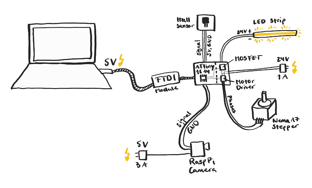
The individual components of the electronics are shown in the image.
Electronic Components
The core of the electronic components is the main board bearing an ATtiny1614 microcontroller. It has several I/O devices. First of all, a hall sensor is used to measure the angles of the rotation. It is powered by the board itself.
Next, two output devices are used, an LED strip and a NEMA 17 stepper motor. Both of them require an additional power source, which is implied with a power supply generating 24 V and up to 1 A. The power is supplied to the LED strip via a MOSFET allowing for controlling its brightness and to the motor via a motor driver. For more details about the components on the main board, please refer to its documentation.
Lastly, the Raspberry Pi camera is connected to the main board via a signal pin and a common ground. However, the camera has its own power supply.
All of these I/O devices are controlled via a user interface on a computer. The control signals are then communicated from the computer to the main board via an FTDI module which is also power by the computer and powers the main board.
The Mechanical Components
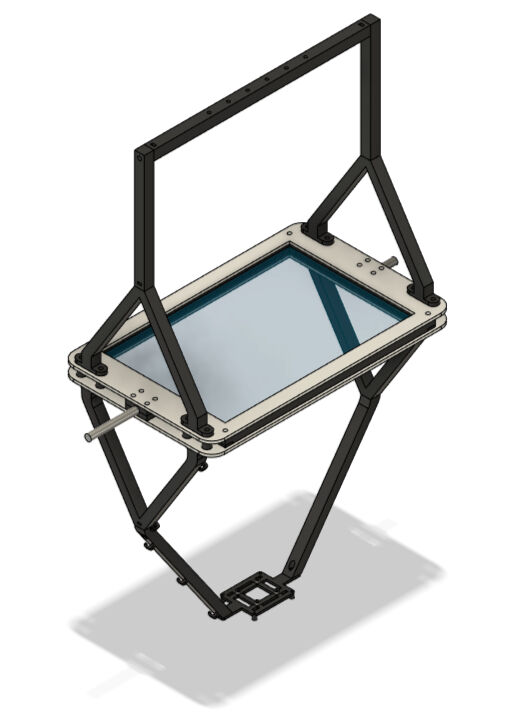
The mechanical components are also split into two sub-systems, namely the parts which are suspended by the frame and the frame itself. The former was mainly designed for the second assignment on computer-aided design. However, I continued the design and documented the manufacturing on the final project page in this section. Please refer to it for the details on this sub-system.
The frame was designed and fabricated during the assignment on computer-controlled machining. Please again refer to the documentation for the details.
Both groups of mechanical parts are simply joined by four ball bearings which will be pressed into the frame to suspend the rotating shaft.
Components Suspended by the Frame

The Frame

Assembled Mechanical Parts
Design and Fabrication of System Integration Parts
In order to bring both sub-systems together, several parts have to be designed and made regarding attachment of electrical devices to mechanical devices, housings including more permanent wire connections and cable routing.
The attachment of the electrical parts to the mechanical ones is mainly designed with the housings. However, two attachments were already implied in previous designs, namely the attachment of the motor to the frame (see here) and the LED strip (see here and here).
Additionally, the attachment of the Raspberry Pi camera has been designed, not in a weekly assignment but in parallel for the final project. Please refer to this section for the details. Nevertheless, the Raspberry Pi camera had no housing yet which I designed for system integration in the first place. Consecutively, I designed other housings and lastly dealt with cable routing.
Housings for Electronics
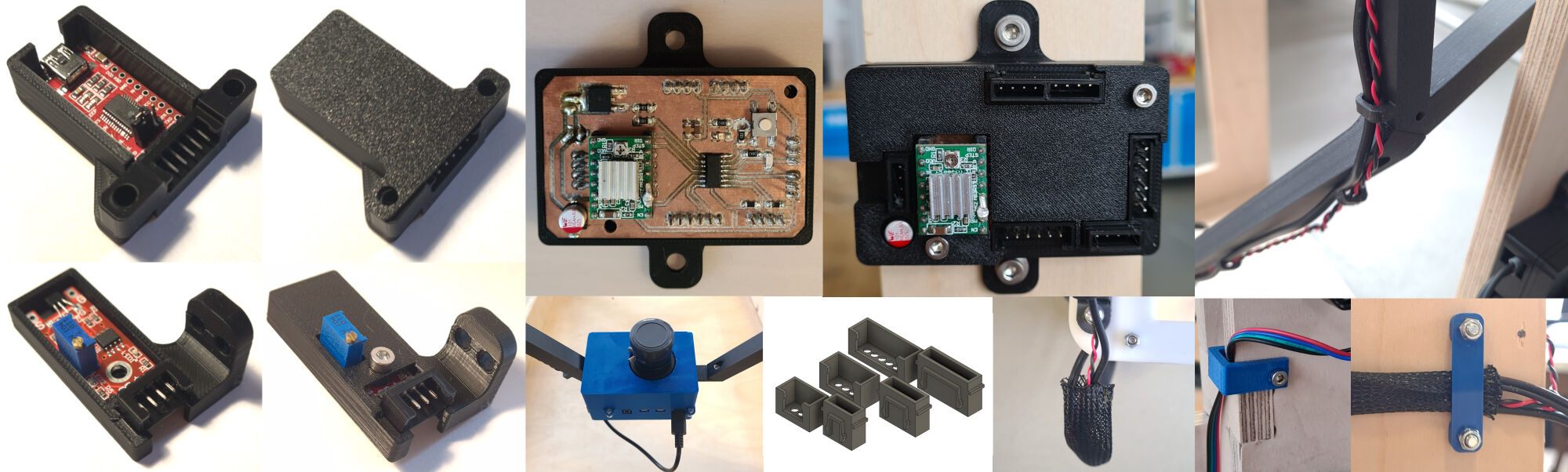
In total, I had to design and make housings for the Raspberry Pi camera, the hall sensor, the FTDI module and the main board. For all, except for the camera, I used 3D Printed JST connectors to establish a more permanent cable connection that only using jumper cables.
3D Printed JST Connectors
In order to design 3D printable JST connectors, I got inspired from this part on Thingiverse. I downloaded the female and male part of the connector for 3 pins and remodelled it in Fusion 360 with the exact same dimensions. However, for the file from Thingiverse, some kind of inserts were used which I did not have. Instead I added a rectangular cut in the top of the male connector to be able to insert female jumper cables. This however caused a very thin wall which is why I had to increase the dimensions of the rectangular base profile slightly. The final dimensions for the base profiles for the male and female connector are shown below.
Base Profile of Female Connector
Base Profile of Male Connector
To create the connector pieces that interlock, I started sketches on the sides of the base shape of the connector. The sketches are shown below.
Connector Sketch for Female Part
Connector Sketch for Female Part
In total, the JST connector parts shown in the image were designed with the sketches above.
As I had to change some aspects of the original Thingiverse files, I test printed several JST connectors with slightly different tolerances. For this, I used a BambuLab C1 Carbon with the textured PEI plate and PLA as the material. In addition to the profile "0.12mm High Quality @BBL X1C", I used the default settings with no support structures. However, the print bed adhesions was very small and therefore I added two layers of a raft.
Design of the JST Connector Parts
With these test prints, the dimensions of the parts converged to the ones shown in the sketches above. Based on these dimensions, I furthermore created connectors for four and six pin headers. These are shown below as well.
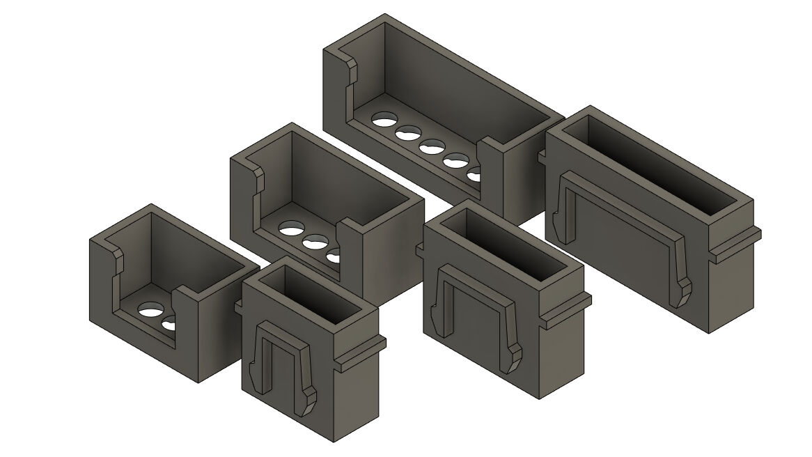
Design of the JST Connector Parts for Three, Four and Six Pin Headers
Raspberry Pi Camera Housing
For the housing of the Raspberry Pi camera, I designed two parts that can be put around the camera from both sides and fixed in this position with M2.5 screws.
For the part on the side of the Raspberry Pi board, I started with sketching the outer dimensions of the Raspberry Pi which I found here. The missing dimensions were measured with a calliper.
Sketch with Dimensions of Raspberry Pi 4
With this sketch, I extruded the all profiles for 2 mm to create the baseplate for the housing.
The walls except for the parts where connectors protrude were extruded for 19.54 mm. This is the result of the thickness of the board of about 2mm, the height of the plastic parts on female jumper cables of 15 mm and the height of the pins of 2.54 mm. This was done to secure the female jumper cables on the GPIOs of the Raspberry Pi. Here, the idea was to insert the plastic pieces of the female jumper cables through a hole and then slide them at the cable to the side to the according GPIO. When tightening the case on the Raspberry Pi, the black plastic piece of the jumper cables gets then trapped between the case and the pin.

Insertion Hole for Jumper Cables
However, this required also an according insert and the holes for sliding. For this, I drew another sketch on the inside of the case and cut out the sketched profile as shown in the image.
To finish the part of the housing for the Raspberry Pi, I had to create some space where the ribbon cable can escape and reach the camera module. The results are shown in the image.
Lastly, I created some protrusions where the board can lay on. These are extruded only by 17.54 mm to create a difference in height of 2 mm which allows the board to sit flush with the top end of the part.
Part of the Case for Raspberry Pi
For the second part around the camera lens and the module, I extruded all parts of the wall for 25 mm and closed the shape with an additional 2 mm shape in the top creating a hollow 3D shape. However, to make the lens of the camera fit through the housing, I added a circle with a diameter of 36 mm positioned in the middle of the four screw holes on the Raspberry Pi board.
Furthermore, the housing must allow the the camera mount which attaches the camera to the remaining parts suspended by the frame to reach through the walls. For this, I created two cut-outs on either side of the housing with the according dimensions.
Circular Cut-Out for Lens
Cut-Out on Side for the Diagonal Arm of the Camera Mount
Cut-Out on Side for the Mount Par of the Camera Mount
Next, I split both parts at the horizontal plane in the according height. With this, the parts a both easily 3D printable.
However, because of this, I had to create some parts which allow me to assemble the two halves of the housing. For this, I attached in total four protrusions with small circular holes to insert M2.5 bolts through it. The protrusions are shown below.
Lastly, I used the "Offset Face" tool in Fusion 360 with an offset of -0.2 mm on all inner walls and added some fillets to the outside edges and the protrusions. The result is shown below.
Finished Design of the Housing for the Camera from One Side
Finished Design of the Housing for the Camera from the Other Side
This housing was 3D printed on an Ultimaker S5 with blue PLA and the profile "Fine - 0.1 mm". Here, the default settings were used except for enabled "Tree" supports and disabled brim.
After printing, I removed the tree supports simply by breaking them away and placed both halves of the housing around the Raspberry Pi camera. Here, I firstly inserted the two female jumper cables through the hole and then plugged them onto the right GPIO. Next, I closed both housing halves onto each other and fixed their positions with four M2.5x10 bolts and nuts.
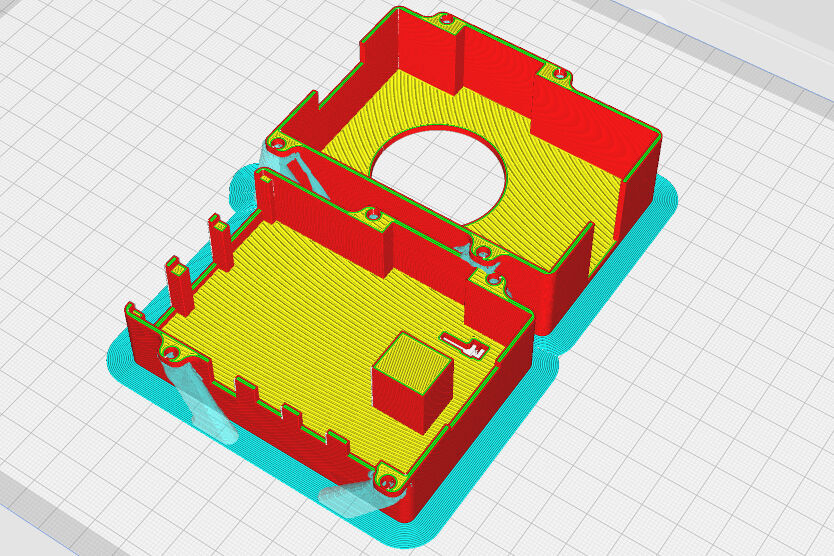
Housing for the Raspberry Pi Camera Sliced in Cura
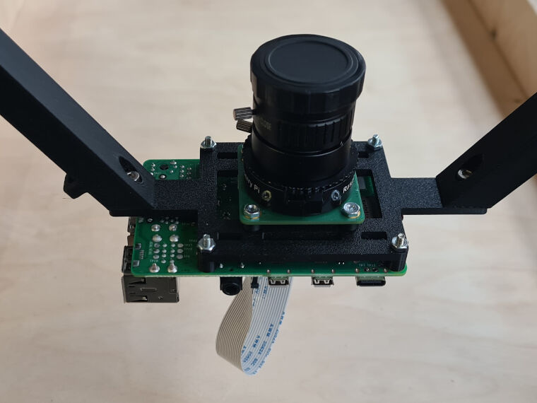
Raspberry Pi Camera without the Housing
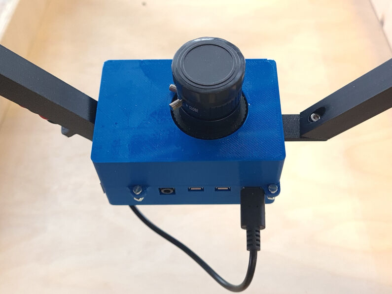
Raspberry Pi Camera with the Housing
Hall Sensor Housing
For housing the hall sensor, I made use of the designed JST connectors, i.e. the four pin connector, as the sensor has four pins, namely an analog output, VCC, GND and a digital output.
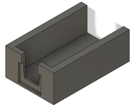
I started designing the housing for this sensor with an initial sketch consisting of two rectangles. The inner one has the dimensions of the rectangular board of the hall sensor which were measured with a calliper and the outer one was placed in an offset of 2 mm to all four sides.
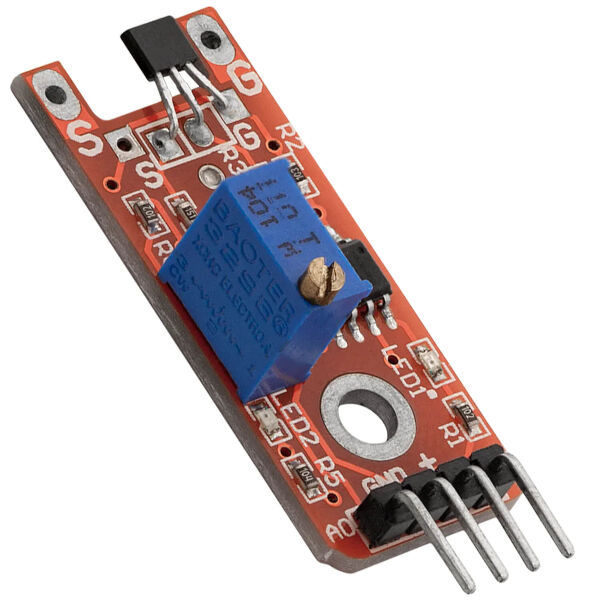
Hall Sensor
The inner rectangle was extruded for 2 mm and the outer for 5 mm creating an initial box where the sensor could be placed in.
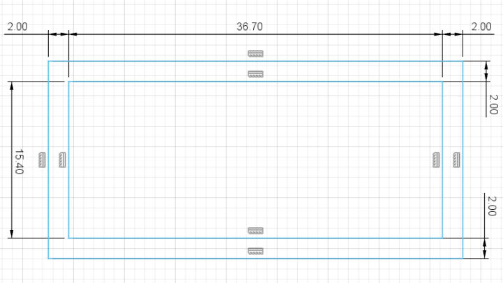
Initial Sketch for Hall Sensor Housing
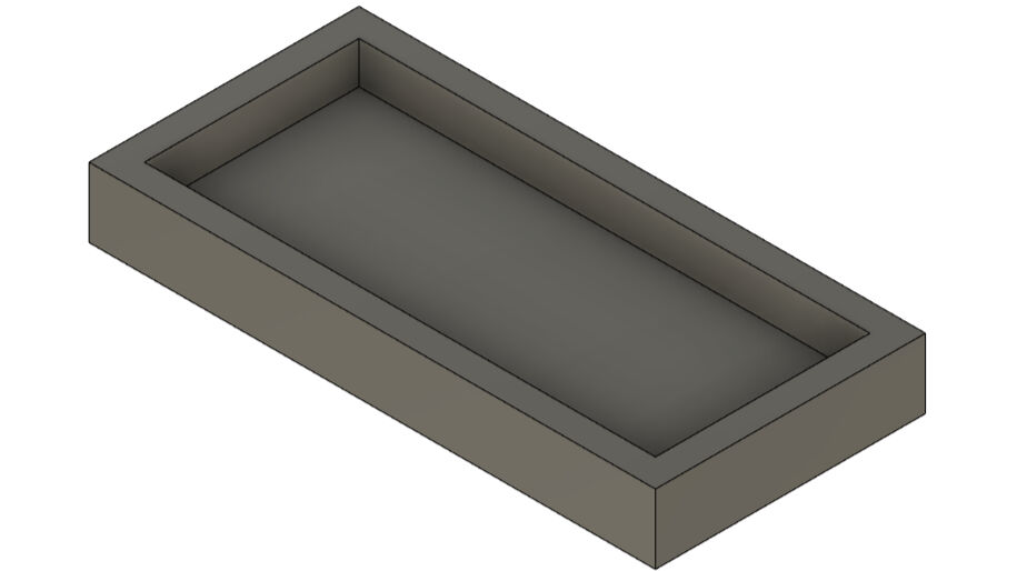
Extruded Initial Sketch
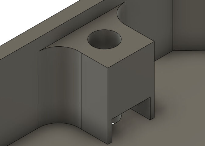
On the plane of the top surfaces, I created a second sketch with a circle for a circular cut-out at the same position as the hall sensor to be able to attach the sensor with a bolt to the housing. Furthermore, I drew small rectangles in the bottom corners to hold the board in place even without a screw. The walls and the rectangles were extruded for 2.5 mm and the hole was cut. Lastly, I added a small chamfer to the protruding edges of the small rectangles in the corners with the parameters "Distance" set to 3 mm and the "Angle" to 15° to be able to insert the board into the housing.
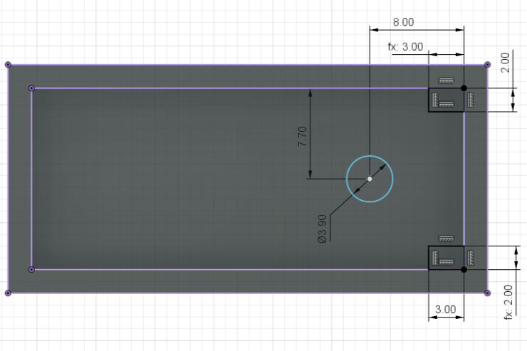
Second Sketch for Hall Sensor Housing
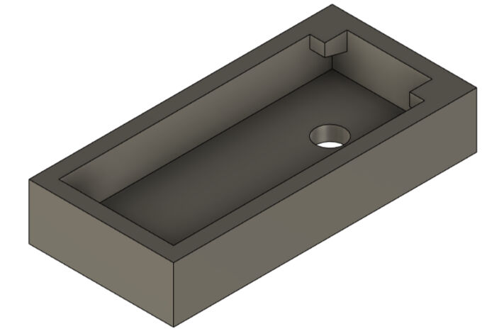
Basic Housing for Hall Sensor
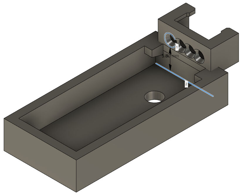
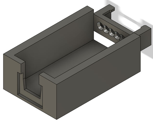
Then, I placed the female JST connector with four pins on the end of the box. Here, as shown in the image, the frontal face of the connector is placed symmetrically and flush with the inner face of the box. The midpoints of the circular holes in the connector are 5.8 mm away from the inner bottom face of the box (see image).
As this design of a combined connector and box would not only be almost impossible to manufacture, also with 3D printing, but would also make it impossible for the sensor to be placed in the housing, I left the two bodies separate. Only the overlapping volume of both bodies, the box and the connector, was subtracted from the box.
Connector Placed for Housing
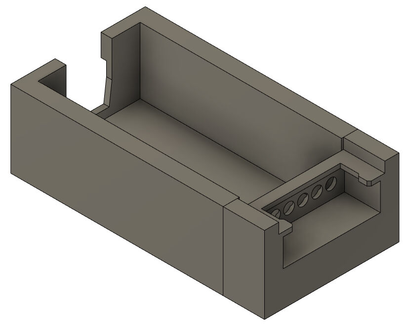
However, the JST connector is floating due to this and therefore, I had to design a fixture. In this case, I created a structure that is attached to the main box of the housing and wraps around the connector with a press fit. For this, I drew a sketch and extruded it from the bottom of the box to the opening of the JST connector, i.e. 6.8 mm.
Sketch for JST Connector Fixtures
JST Connector Fixtures
Next, I designed a lid for the box that can be tightened with a bolt through the screw hole in the sensor to the rest of the housing. For this, I used the outline of the box of the housing and extruded the complete profile except for the fixtures for 1 mm. On top of it, I created a hollow cylinder with its midpoint at the same position as the screw hole with a wall thickness of 0.85 mm and a height of 3 mm. Lastly, I had to create cut outs for the potentiometer and the
Sketch for Cut-Outs in the Lid
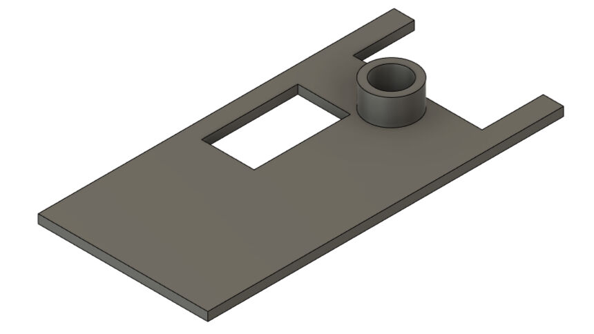
Lid for the Housing
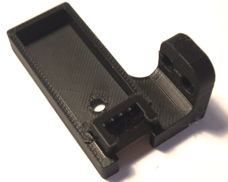
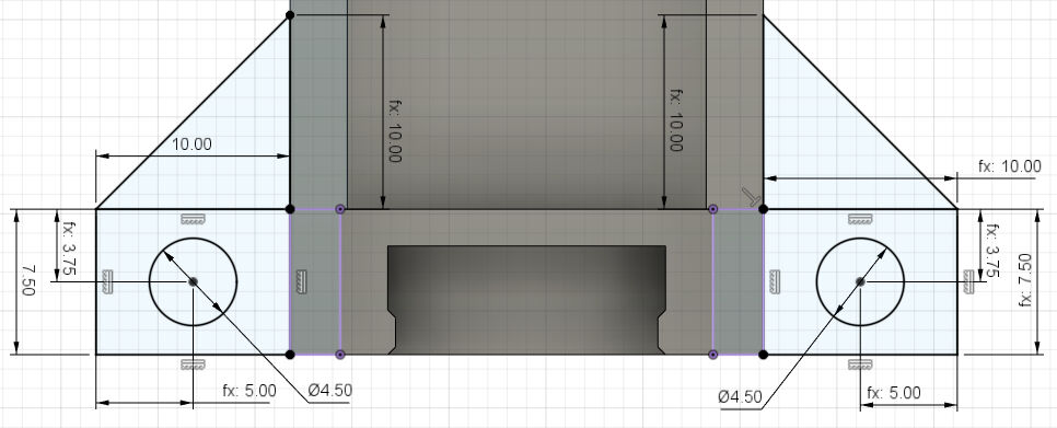
Lastly, the attachment of this housing to the frame was left. Here, I simply created a small "L"-shaped structure with two screw holes on the end such that it can be mounted on the side of the frame with the hall sensor in parallel to the length-axis of the rotating shaft. Some fillets were added to decrease the sharpness of the edges.
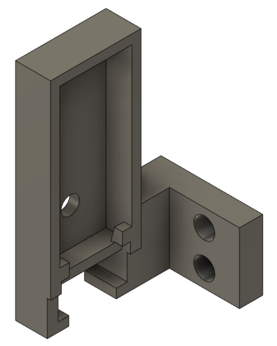
Added Attachment to Frame with "L"-Shaped Structure and Screw Holes
Housing for Hall Sensor from the Left

Housing for Hall Sensor from the Right
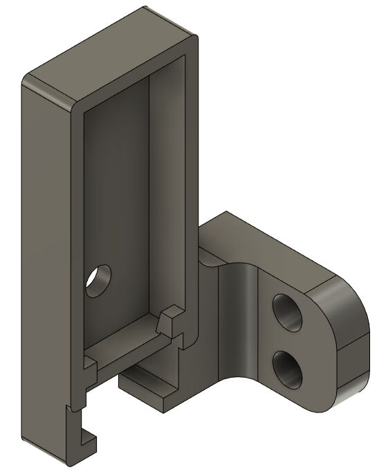
After the design was finished, I noticed that I had to place the sensor further away from the frame. Therefore, I extruded the face that should touch the frame for 7.5 mm to create a small block. This completed the design as shown below.
Block for Attachment Further Away
Housing of Sensor with Attachment Block
This design was printed with the same settings as the JST connectors with the raft only enabled for the JST connector. The block however was printed on an Ultimaker S5 with the "Normal - 0.15 mm" profile, the standard settings and with blue PLA.
After printing, I assembled the parts by firstly pressing the female JST connector into its position at the housing. Next, I inserted the hall sensor and lastly, I placed the lid on it. All parts were tightened using an M3x12 bolt and nut.
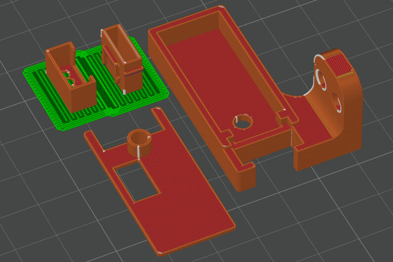
Housing for Hall Sensor Sliced in Bambu Studio
JST Connector Fixed with Press-Fit
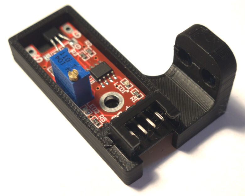
Hall Sensor in Housing
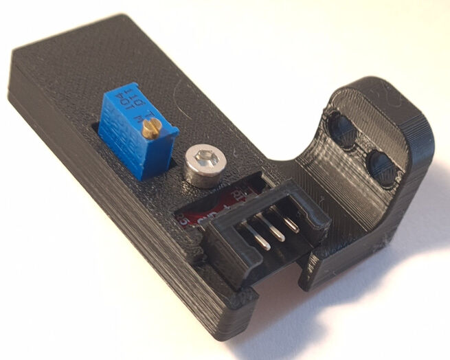
Lid Closed with M3x12 Bolt and Nut
These parts were then all attached to the frame. For this, I drilled two 4 mm holes at the desired position and inserted M4x30 bolts through the sensor's housing, the block and lastly the frame. Then, I used two M4 lock nuts to secure its position next to the magnet on the rotating shaft.
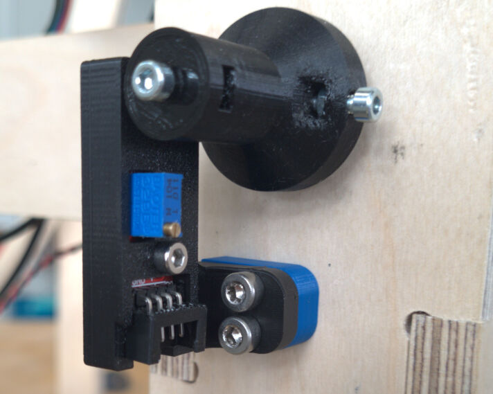
Attached Housing for Hall Sensor
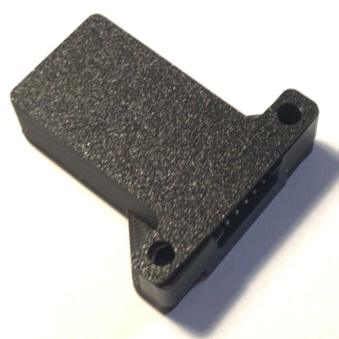
FTDI Module Housing
To use the user interface to control the input and output devices, an FTDI module is connected to the main board which uses the UART communication protocol. This module however also needs a housing with a JST connector using six pins.
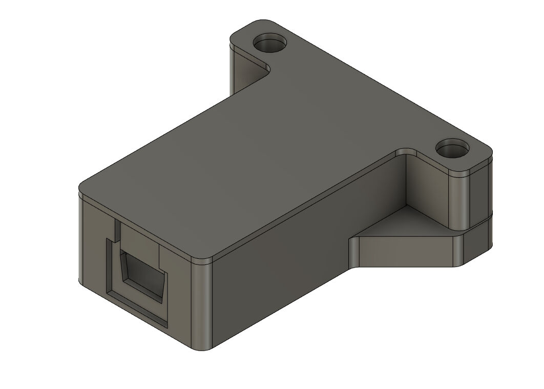
For designing the housing, I again started with an initial sketch in Fusion 360. It consists of an inner and outer rectangle which have a joined right side. The inner rectangle has the dimensions of the FTDI module's board. The outer one is positioned in a distance of 2 mm on the right and 3 mm on the top and bottom. The walls were extruded for 14 mm and the complete profile for 2 mm.
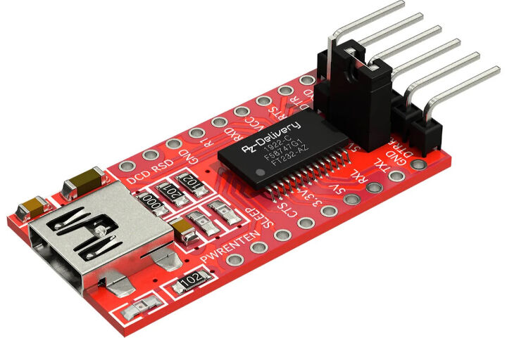
FTDI Module
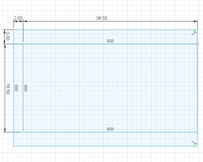
Initial Sketch of the Housing
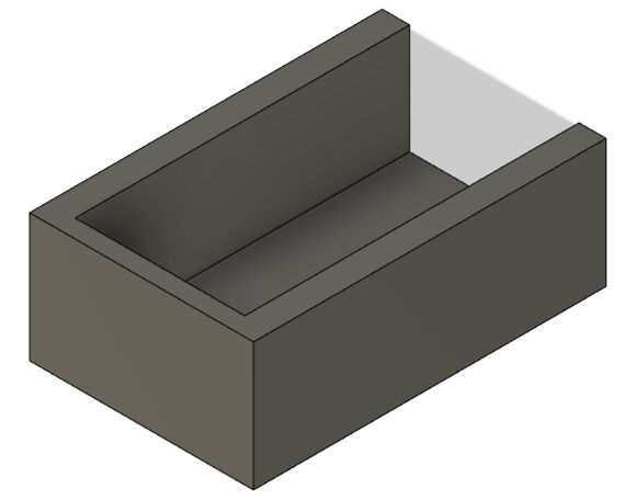
Base Box for the Housing
As the FTDI module has a mini USB connector on its end, I had to create space for the plug. For this, I drew a sketch on the left side of the wall with the shape of the mini USB port and an opening to the top to make it 3D printable and a rectangle around it to allow the USB cable to get closer to the FTDI module. I cut out the mini USB port shape completely and the rectangle for half of the wall, namely 1 mm.
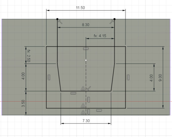
Initial Sketch of the Housing
Base Box for the Housing
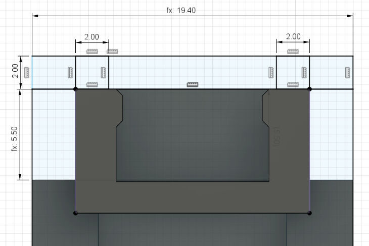
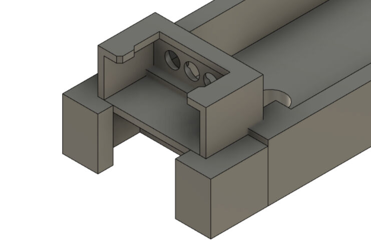
Next, I added the JST connector with six pins and positioned it symmetrically at the open end of the housing in a height of 5.5 mm. Then, I the space on the side of the connector and the bottom was filled with volume to sit flush with the housing. The top was left open.
Positioned JST Connector
JST Connector in Housing
To connect the housing with the part including the JST connector, another structure was created. The idea was to combine parts with screws that are also used to attach the FTDI module to the frame. For this, I created the sketch below which is on the base plane of the housing.
Sketch for Screw Holes to Assemble Parts
The two wing-like structures were extruded for 5 mm and joined with the housing. In addition, the rectangles with the circular holes were extruded on top of it for 8.7 mm with a distance of 0.3 mm. These were later joined with the part of the JST connector.
Screw Holes Parts in the Bottom
Screw Holes Parts in the Middle
Lastly, I drew a sketch on the topmost. This was used to create the complete outline of the parts and finally extrude this part to create the lid with a thickness of 1 mm.
To smoothen the design, I added some fillets on outside edges of the design.
Lid for FTDI Module's Housing
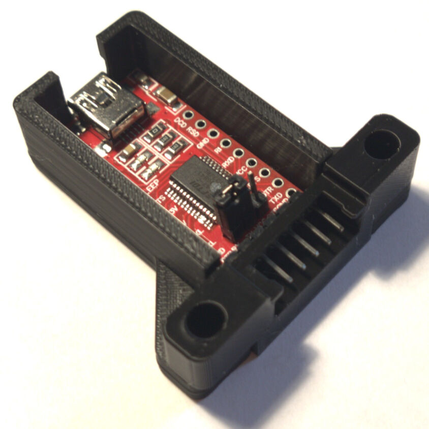
Housing for FTDI Module from One Side
Housing for FTDI Module from the Other Side
These three parts, namely the housing, the part with the JST connector and the lid were 3D printed with the same settings as for the test prints of the JST connectors with a raft only enabled for the JST connectors
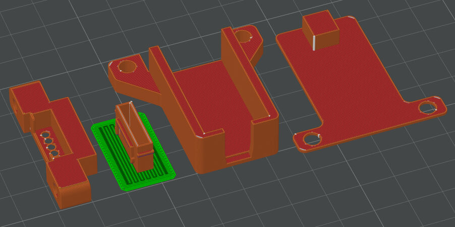
Housing for FTDI Module Sliced in Bambu Studio
The parts were assembled by firstly placing the module in the housing, then by mounting the female JST connector part at its end and lastly by placing the lid on the top. The positions were fixed later by attaching the housing to the frame (see here).
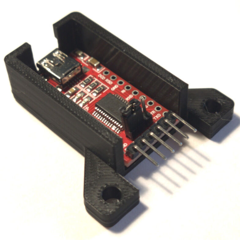
Housing with FTDI Module
Housing with Added JST Connector
Housing with Lid
These parts were fixed in position on the frame using two M4x40 bolts. Again, two 4 mm holes were drilled in the according position, then the bolts were inserted and lastly, M4 lock nuts were used to secure the position of this housing.
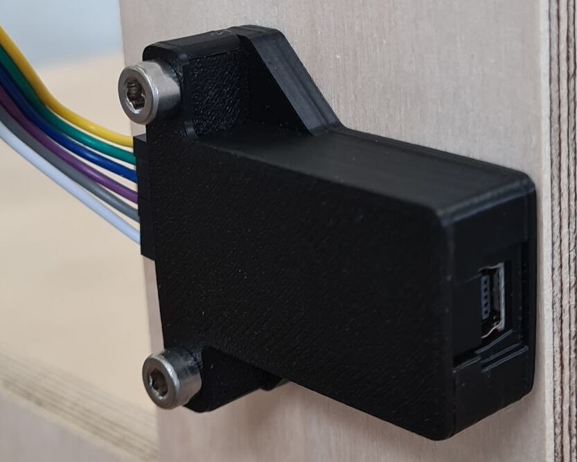
FTDI Module with Housing Attached to the Frame
Main Board Housing
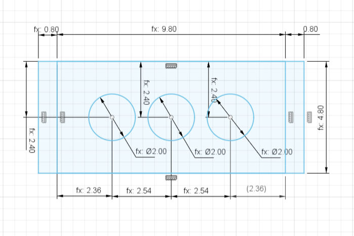
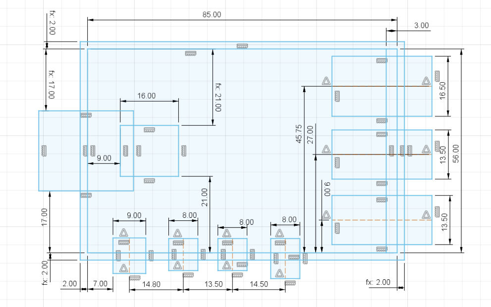
As the last housing, I designed the housing for the main board. For this, I exported the physical layout that I designed in KiCAD by clicking on File > Export > SVG.. and selecting the F.Cu layer. This .svg file was then imported into a new Fusion design via Insert > Insert SVG. In addition to the drawing in the .svg file, an outer rectangle in a distance of 2 mm and circles around the screw holes were added.
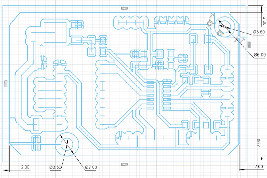
Initial Sketch for Housing of Main Board
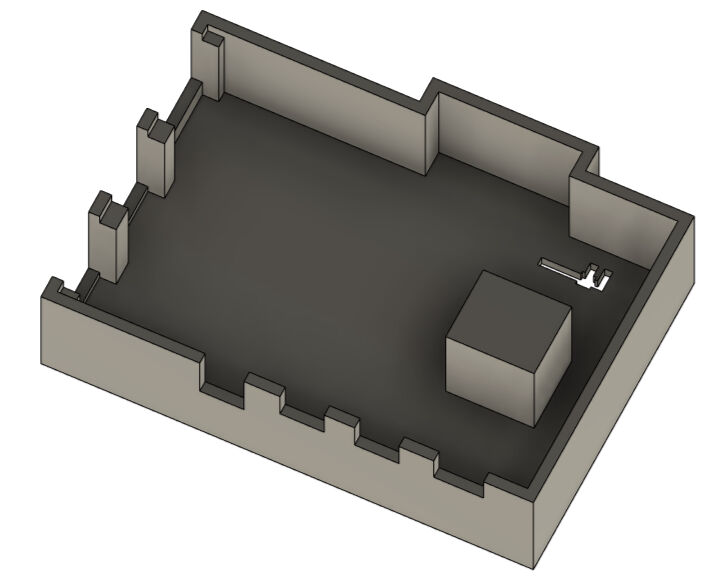
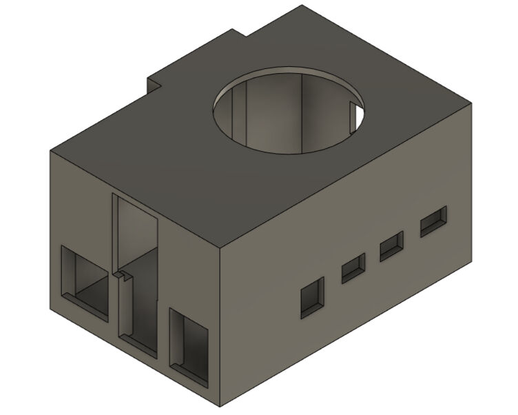
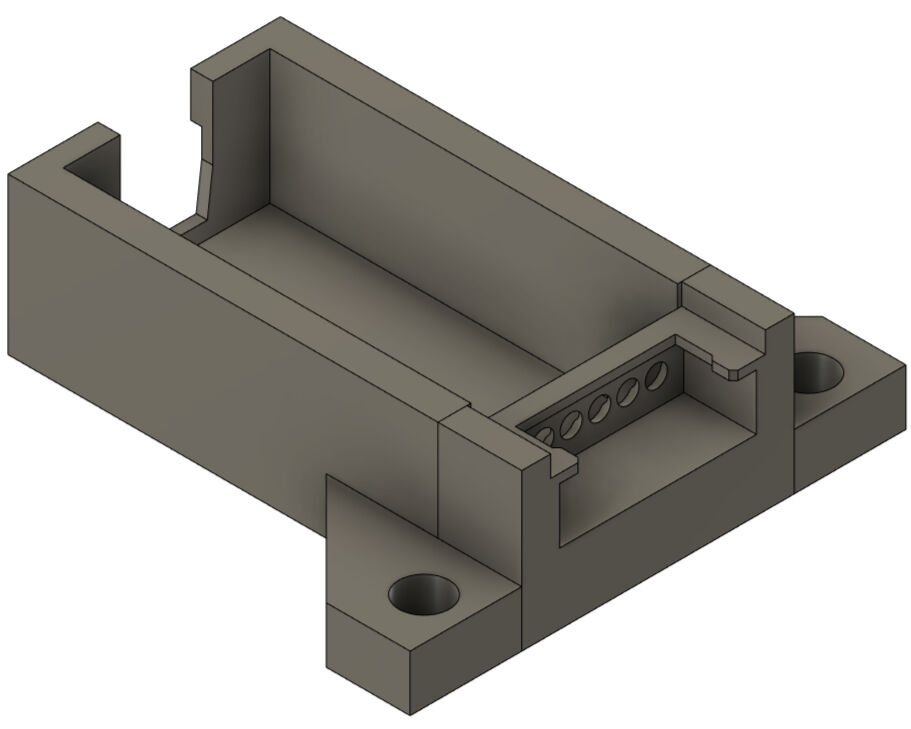
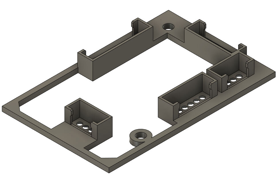
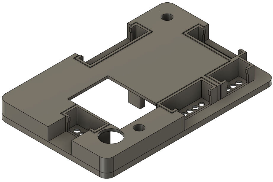
With this sketch, I extruded the walls for 12 mm and the rest for 2 mm. This created the base for the bottom of the housing. The idea is to place the board then on top of the current design and fix it with screws. However, firstly, the outlets for the cables that are fixed in the screw terminals must be created. For this, I used 7 mm wide rectangles that I negatively extruded onto the baseplate.
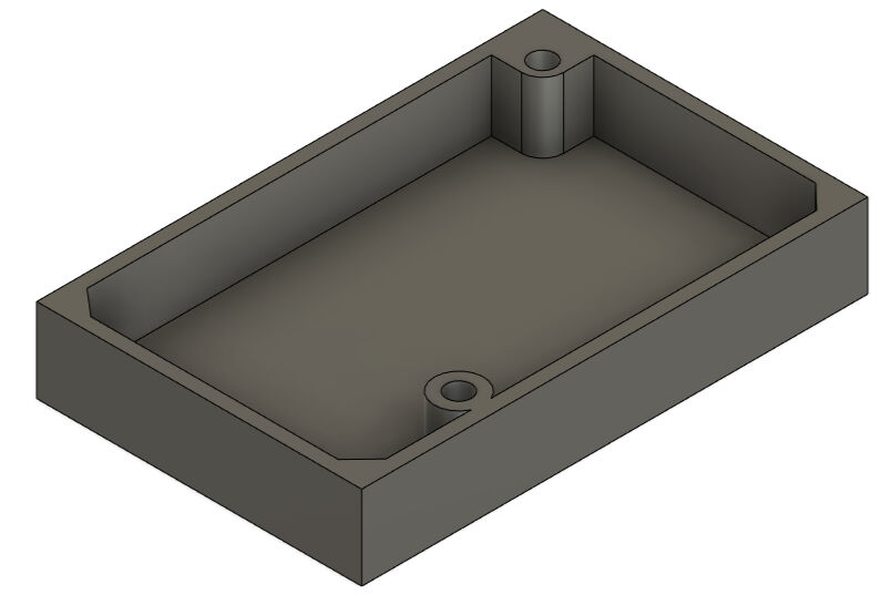
Basic Bottom Part of the Housing
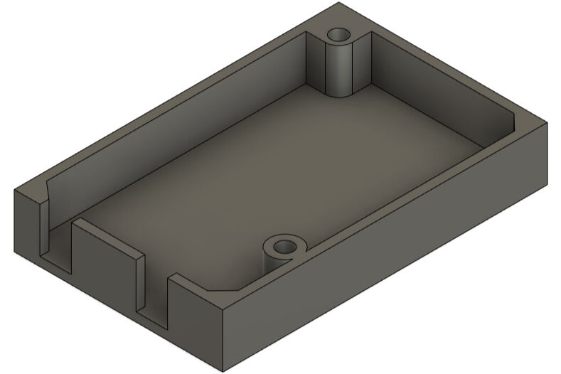
Cut-Outs for Wires Connecting to the Screw Terminals
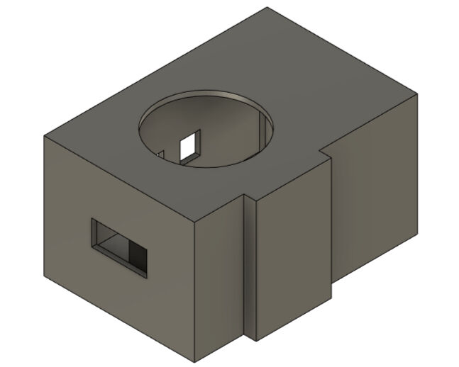
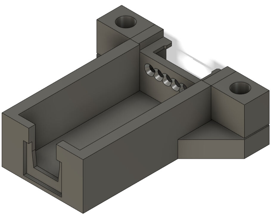
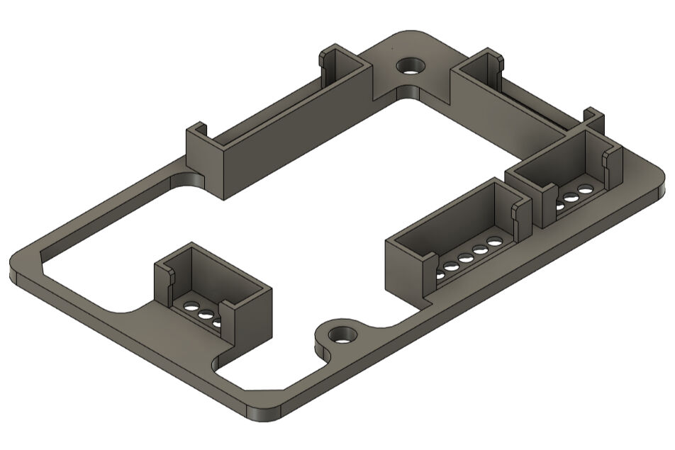
Next, added the actual walls around the board by extruding the walls for 1.8 mm. Here, I also added fillets for a smoother outline.
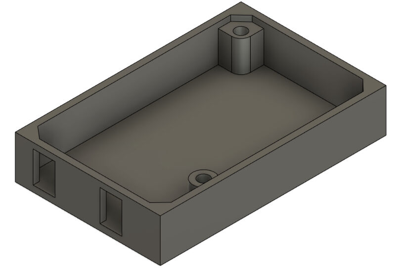
Creating Walls for the Housing
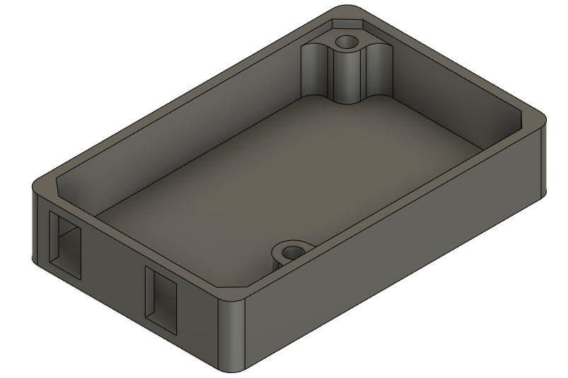
Adding Fillets
With this design, the PCB can sit on top of the spacer for the screw holes. However, the bolts would have to be inserted through the complete housing. Instead, I added nut inserts in the bottom of the spacers. For the screw hole in the corner, you can see the sketch and result below. The height of the slot for the nut is 3 mm and is placed on the baseplate of the housing.

Sketch for Creating Nut Insert at the Corner Screw Hole
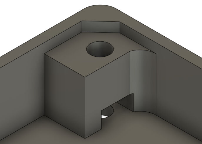
Nut Insert at the Corner Screw Hole
The sketch and the result for the screw hole at the edge is shown below. Here, the height of the slot is again 3 mm.

Sketch for Creating Nut Insert at the Edge Screw Hole
Nut Insert at the Edge Screw Hole
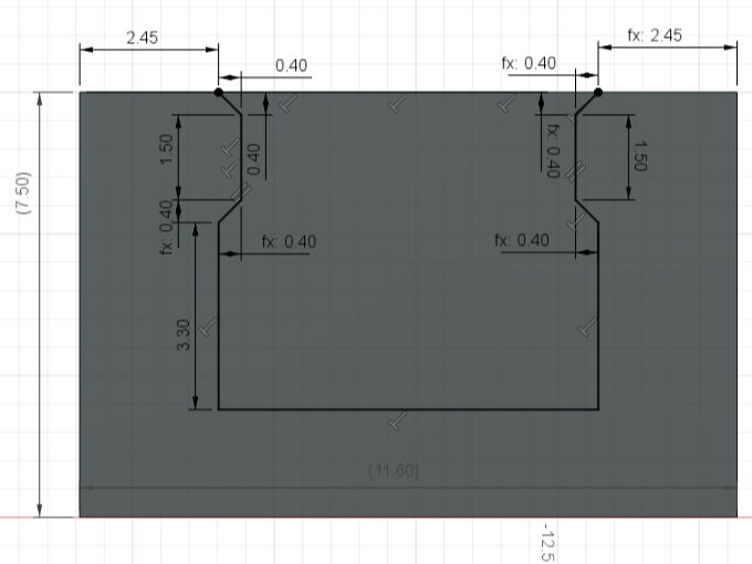
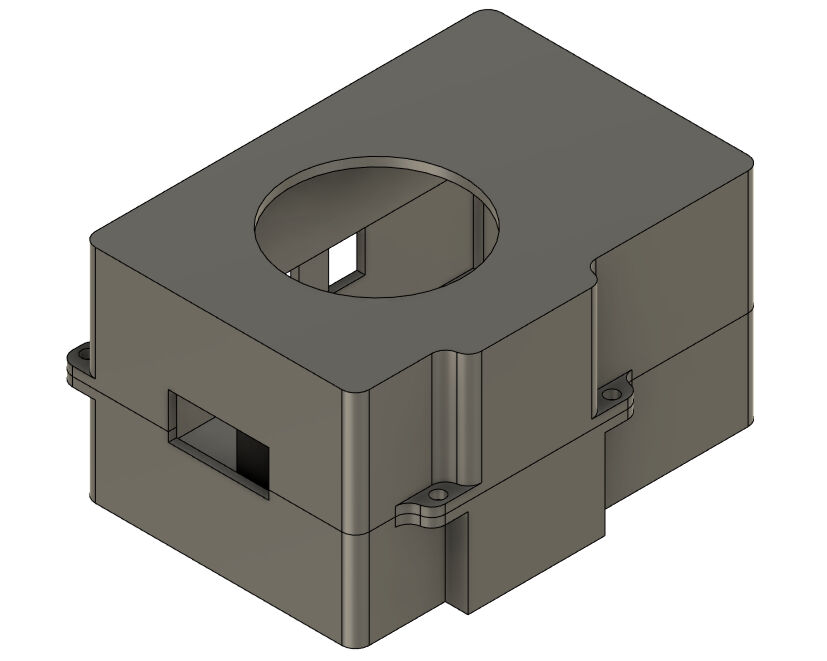
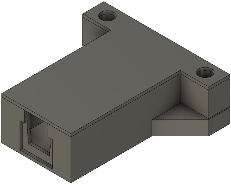
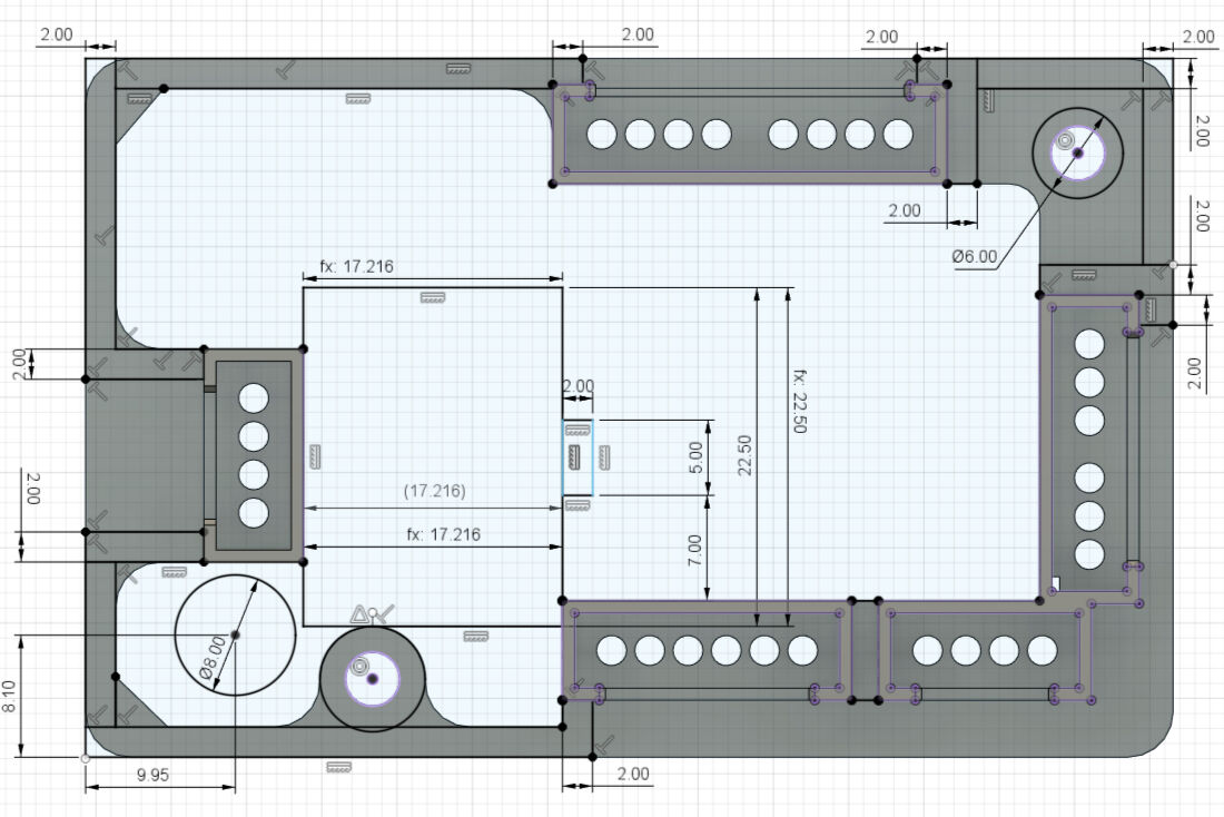
Lastly, for the bottom part of the housing, I had to address the attachment of the housing to the frame. For this, I created a sketch with rectangles on the top and bottom and circular holes in the middle. These profiles were extruded for 3 mm.
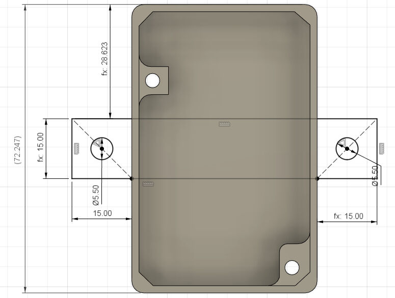
Sketch for Attachment Structures
Structures to Attach Housing to Frame
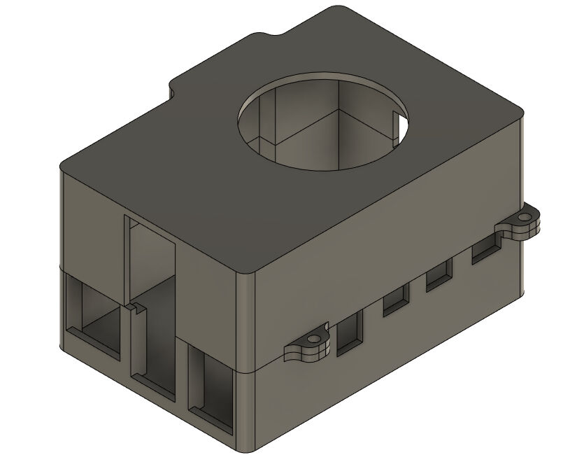
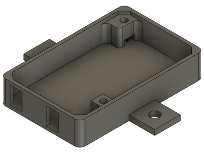
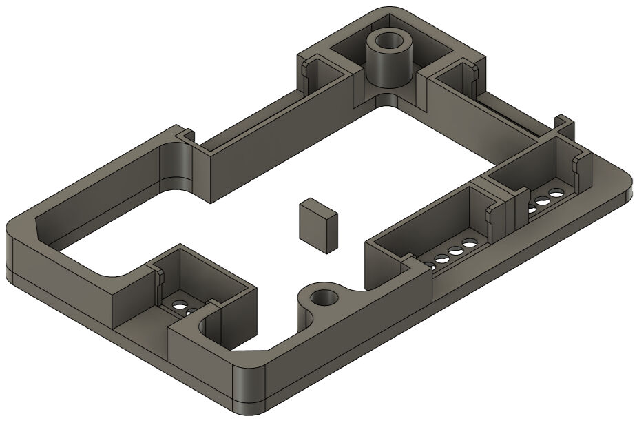
To finish the design of the bottom part of the housing for the main board, I added some more fillets.
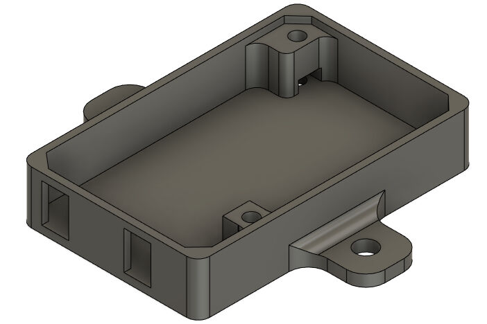
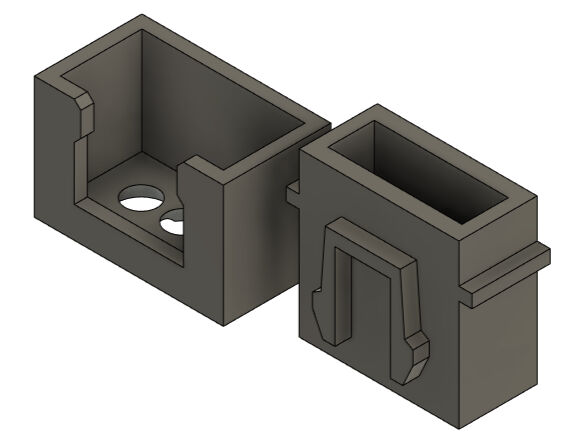
Bottom Part of Housing for Main Board from One Side
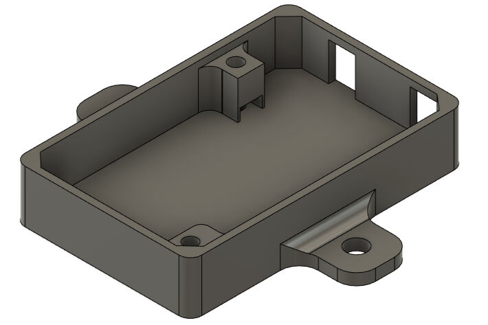
Bottom Part of Housing for Main Board from the Other Side
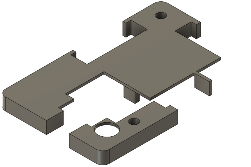
After finishing the bottom part, I continued with the part(s) above the board. Here, my goal was to place the female JST connectors on top of the board and connect them to a single part around the outside. To fix the position of this part, I wanted to use bolts and screw holes. However, I also had to cover the remaining pieces on the board. Therefore, the design above the board consists of a part with JST connectors and on top of it a lid that covers the rest. The bolts then tighten the lid onto the part with the female JST connectors which tightens the board onto the bottom half the case.
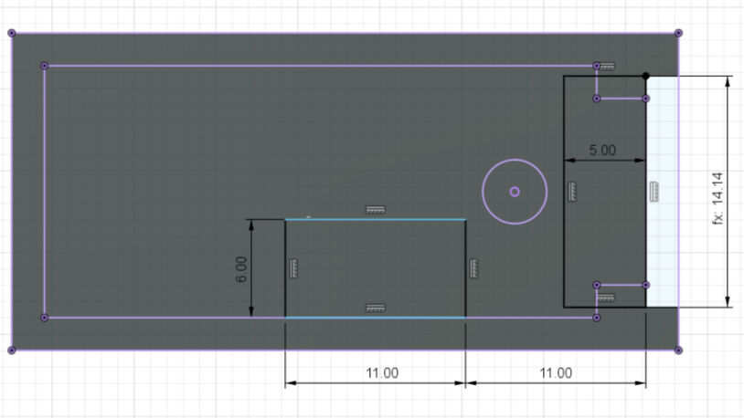
As a logical next step, I designed the part with the female JST connectors. For this, I again imported the .svg file of the F.Cu layer exported from KiCAD and added an outer rectangle to it with the same dimensions and positions as shown for the bottom half of the housing. Next, I used the previously designed female JST connectors and placed them on top of the sketch at the according position as shown in the image
In case for the top two JST connector with four pins and the two with three pins on the right side, their volume overlapped. To work around this, I combined the pair to one body and cut out the overlap. The male connectors were changed accordingly.
Furthermore, the walls and the profiles around the screw holes were extruded for 2 mm. Due to this, the bolts in the screw holes are able to clamp this part onto the board and onto the bottom half of the housing.
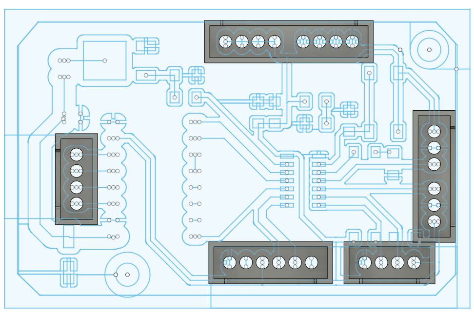
Female JST Connectors Placed at Their According Position
Wall Created Around the JST Connectors
The female JST connectors are however floating right now and have no connection to the remaining parts. To establish this connection, I extruded some profiles between the wall body and the connectors for again 2 mm to be flush with the remaining parts.
JST Connectors Merged with Walls from the Top
JST Connectors Merged with Walls in an Angled View
To finish this part, I added fillets to some essential corners. For example for the screw hole at the edge or for the corners leading to the female JST connector with four pins on the left, the fillets will substantially increase the stability of the part.
Due to this design, the protruding SMT components that are soldered onto the board are still able to protrude.
JST Connectors Merged with Walls
However, the SMT and other soldered components should still be covered. This was the last aspect, I addressed in this design. As shown in the next few steps, I created a lid that is placed in the same height as the top end of the JST connectors. This still allows me to remove the male JST connectors easily.
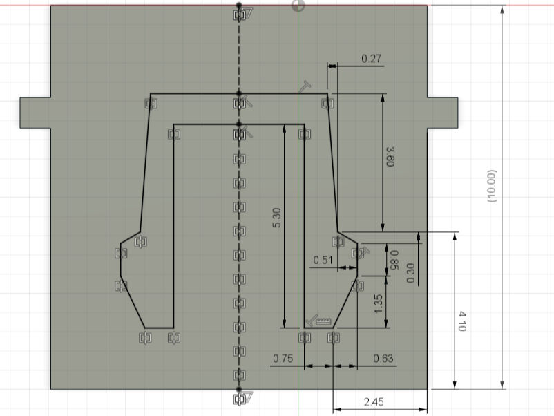
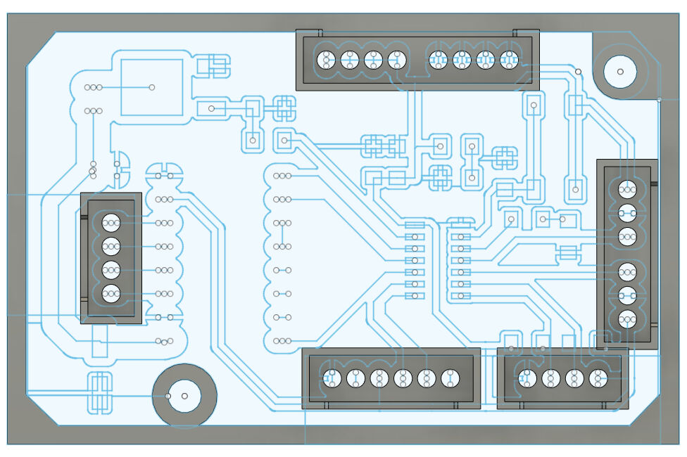
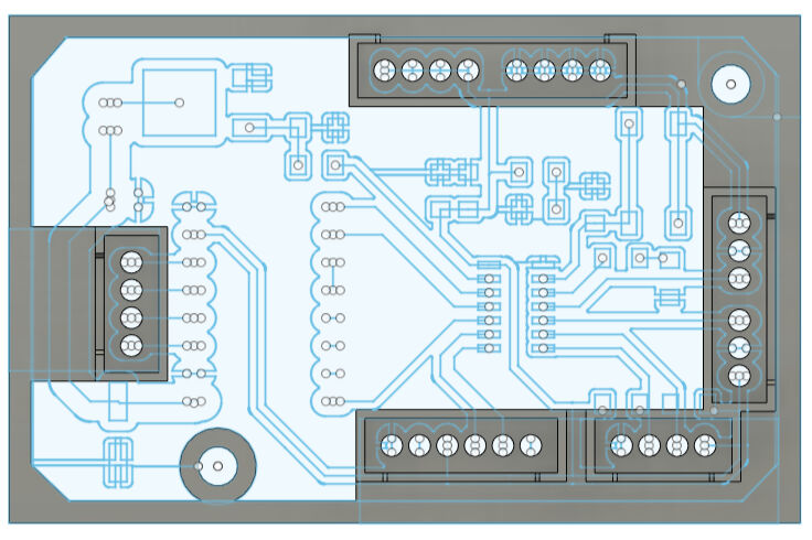
To design the cover, I created a sketch on top of the walls. This sketch mainly consist of the same walls as the part below it but also creates walls leading to the female JST connectors. Additionally, there is one rectangle in the middle which is the outline of the motor driver with a bit of additional spacing. Furthermore, a circle in the bottom left was added showing the outline of the capacitor for the motor's power supply. These two components, the motor driver and the capacitor are namely higher than the intended cover and have to traverse it.
Sketch for the Cover
From the sketch, I extruded the walls by 5.5 mm. Next, the remaining profile was extruded up to the same height but only with a thickness of 1 mm. Then, the created bodies were combined to two bodies.
Walls for the Cover

Cover Added to the Housing
I lastly added some offsets of -0.3 mm to the faces touching the JST connectors. The results are shown below.
Offsets Added to the Cover
The Two Parts of the Cover
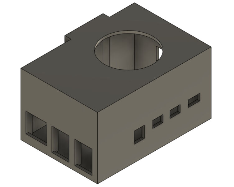
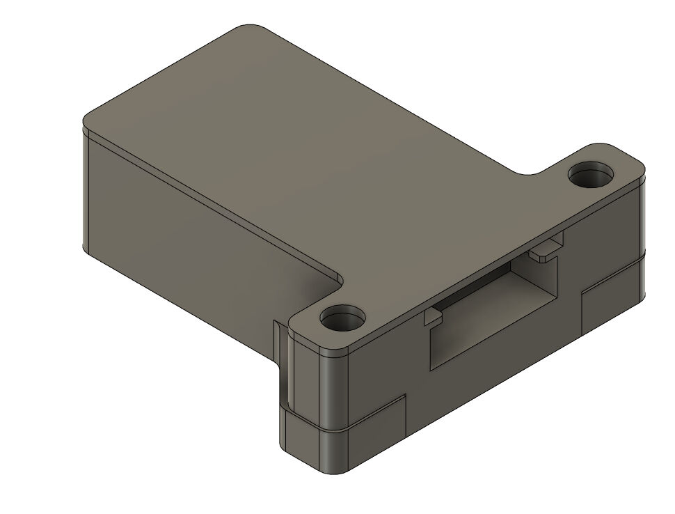
With this piece, I was done with the housing for the main board. The result is shown below.
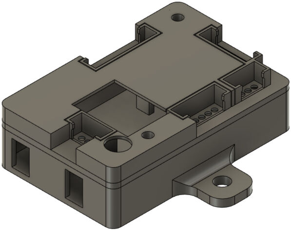
Housing for the Main Board from One Side
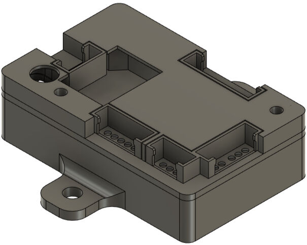
Housing for the Main Board from the Other Side
Next, the parts were 3D printed on a BambuLab X1 Carbon with the same print settings as for the JST connectors. The raft was again only enabled for the JST connectors to enhance their bed adhesion.
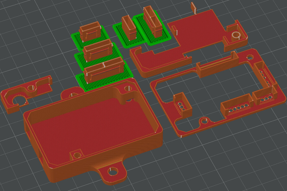
Housing for the Main Board Sliced in Bambu Studio
The printed parts were assembled by firstly inserting two M3 nuts into the according positions in the bottom half of the housing. Next, the board was placed on the bottom half, the part with the female JST connectors was placed on top of it and then also the two parts for the cover. Lastly, two M3x20 bolts were used to fix all parts in their position.
Later, I had to reopen it to route the wires connecting to the screw terminal through the case and tighten them. Then, I was able to finally close the housing.
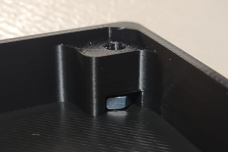
M3 Nut(s) Inserted into the Housing for the Main Board

Main Board Placed on the Bottom Half of the Housing
JST Connector Part Placed on the Main Board for the Housing
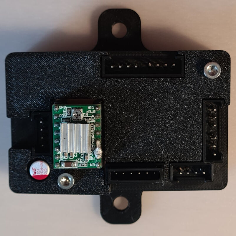
Covers Placed and M3x20 Bolts Tightened for the Complete Housing
Lastly, the housing was attached to the frame by drilling two 4 mm holes at the desired position and inserting two M4x20 bolts with washers through the attachment structures at the housing and the holes in the frame. Two M4 lock nuts were used to secure the position.

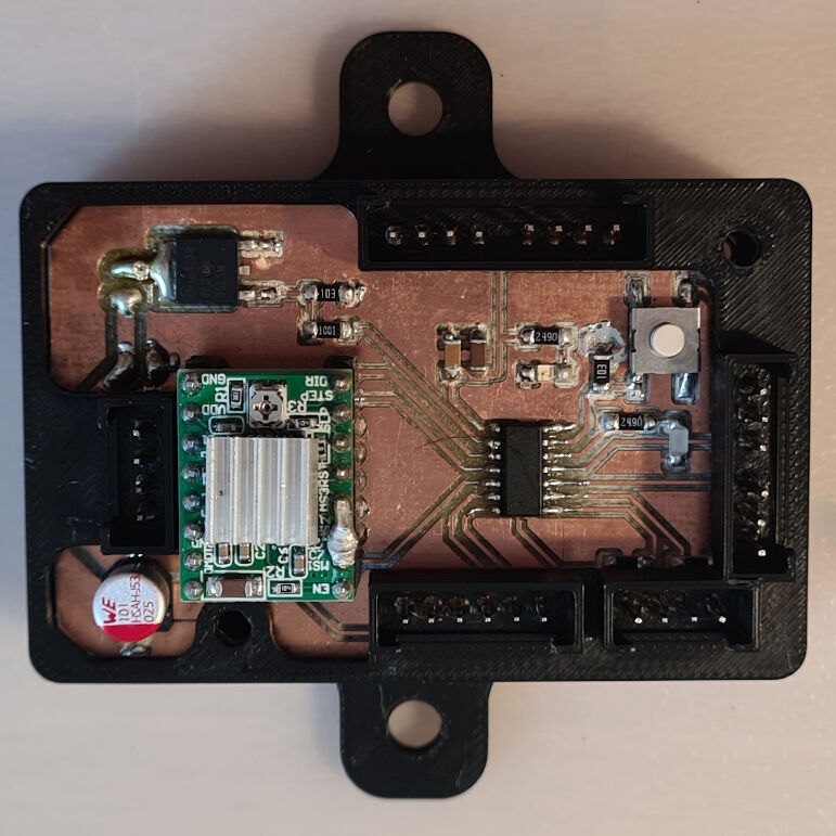
Housing and Main Board Attached to the Frame from One Side
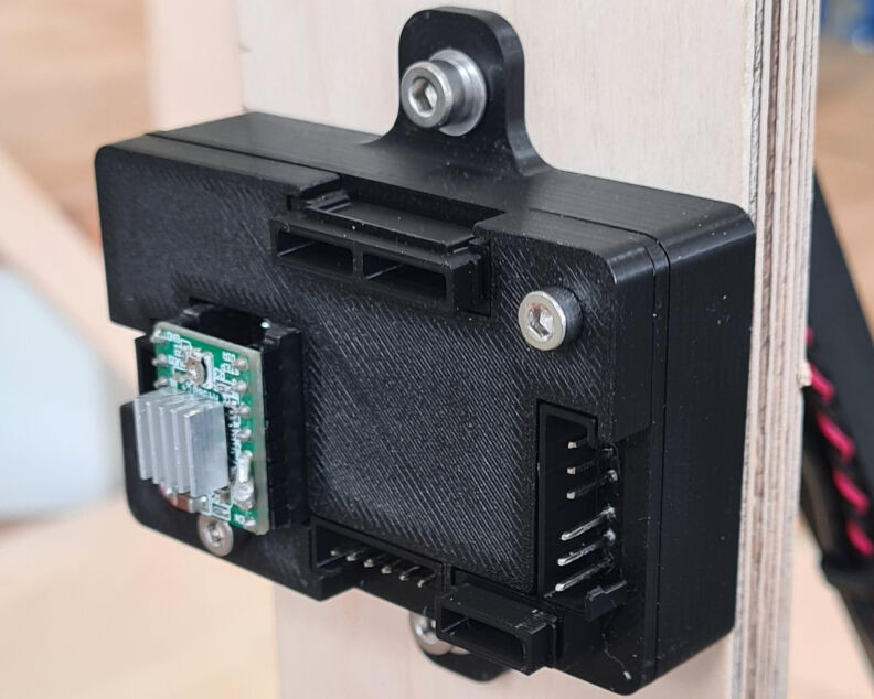
Housing and Main Board Attached to the Framefrom the Other Side
I am really happy with this design as it does not only look aesthetic but also allows me to remove the motor driver easily. I heard that they are easily broken during operation. In case this happens to me, I can quickly take the broken one out and insert a new one.
Cable Routing
In addition to the housings, cable management and routing has to be addressed. Here, three aspects are adressed, namely the cable routing from the camera to the rotating platform, from the platform to the frame and lastly along the frame to the electronic parts.
Cable Routing from Camera to Rotating Platform
In total, three cables must be routed from the camera to the platform, namely the power supply cable, a wire to connect the ground with the power supply and the main board and lastly the signal line which is either high in case the camera should record or low for no recording.
The routing for all of these cables was already implied with a previous design namely with the design of the camera mount system. Here, some cable clips were attached in the design on one side of the arm and fabricated with the arm by 3D printing. Please refer to this section for more details.
Design of Cable Routing from Camera to Platform Along Camera Mount System
Cable Routing from Camera to Platform Along Camera Mount System
Cable Routing from Rotating Platform to Frame
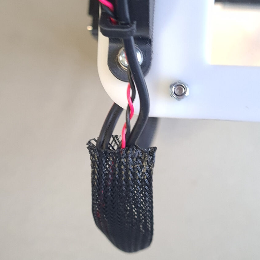
From the platform, the power supply, the ground and signal wire as well as the plus and minus cable of the LED strip must be routed to the frame. This is not trivial as the platform still must be able to rotate from zero to 180 degrees. To allow for such a movement, I placed the cables in a braided sleeve that leads to the bottom of the inner side of the frame's left side panel.
The top end of the sleeve can be left floating, however, for the bottom part, I designed a clip that can be mounted onto the other side of the FTDI module using the same bolts. This part has two screw holes in the same distance as the FTDI and a cross linkage in a height of 5 mm and with a thickness of 2 mm. It was manufactured on an Ultimaker S5 with the "Normal - 0.15 mm" profile and default settings from blue PLA.
Sleeve with Cables for Routing from Platform to Frame in 160° Position
Design of Fixture for Braided Sleeve
Fixture for Braided Sleeve
I attached this piece by loosening the two bolts attaching the FTDI module and removing the nuts. Next, I placed the end of the sleeve between the two screws on the opposite side of the frame's side panel with the end of the sleeve facing to the back. Then, I placed the fixture for the sleeve on the two bolts and tightened new lock nuts on them. This allowed enough movement and deformation of the sleeve without being to loose or in the way.
Sleeve with Cables for Routing from Platform to Frame in 5° Position
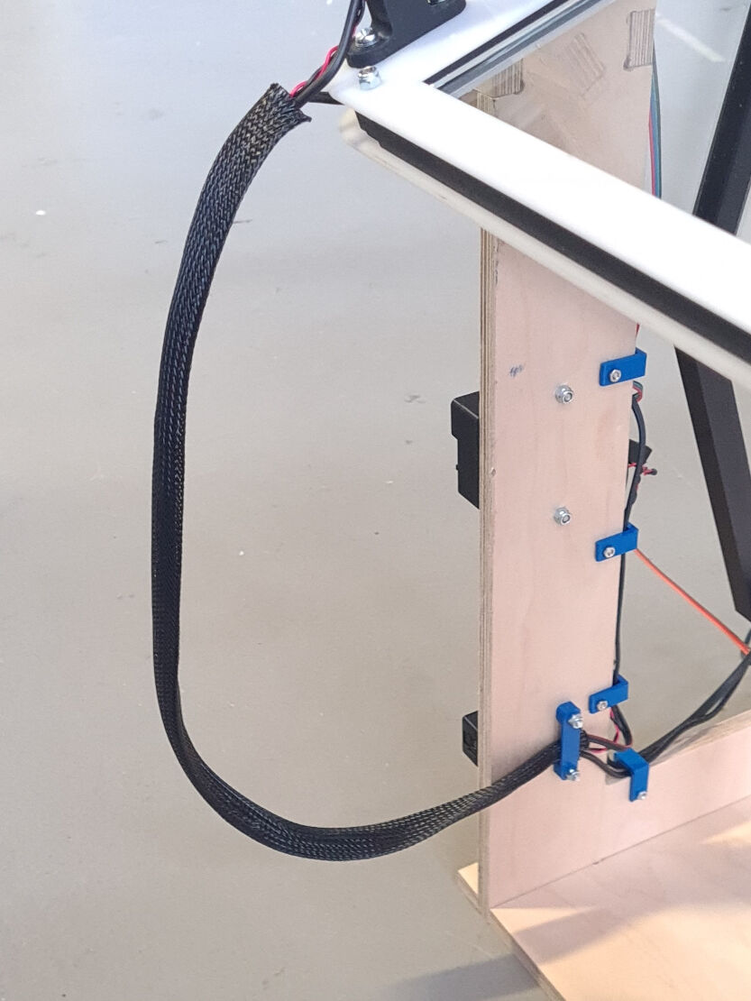
Sleeve with Cables for Routing from Platform to Frame in 160° Position
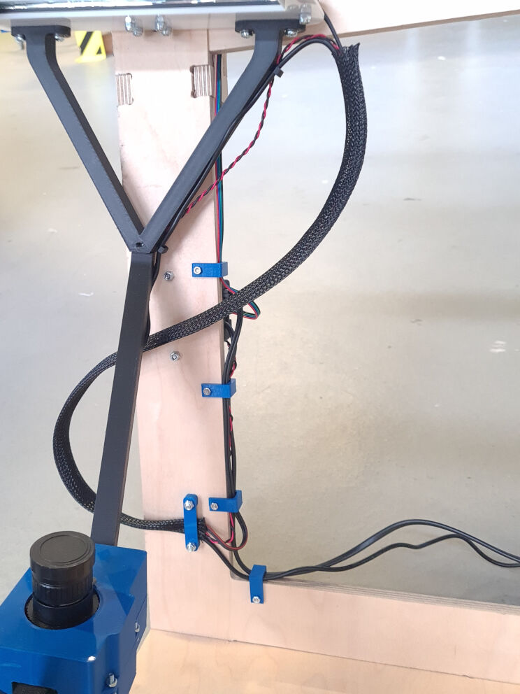
Cable Routing Along Frame to Electronics
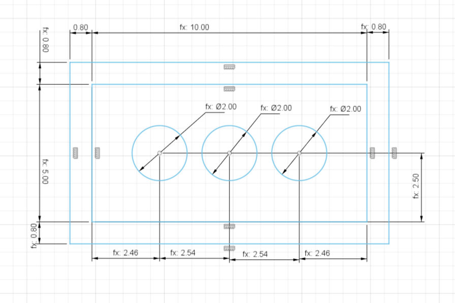
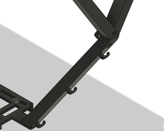
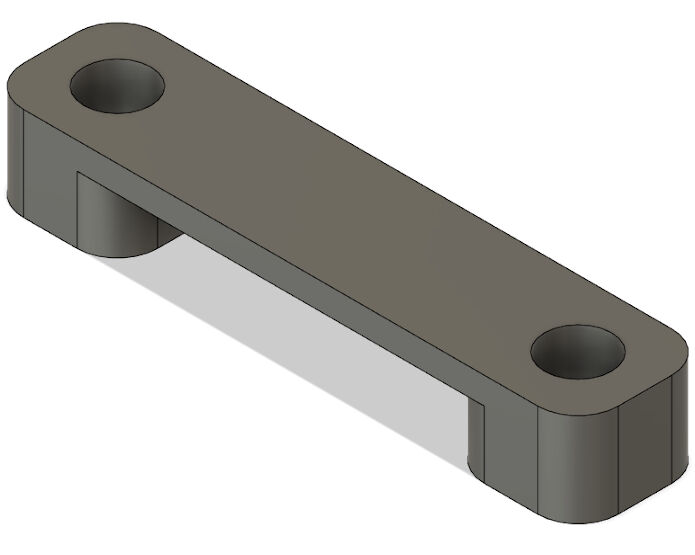
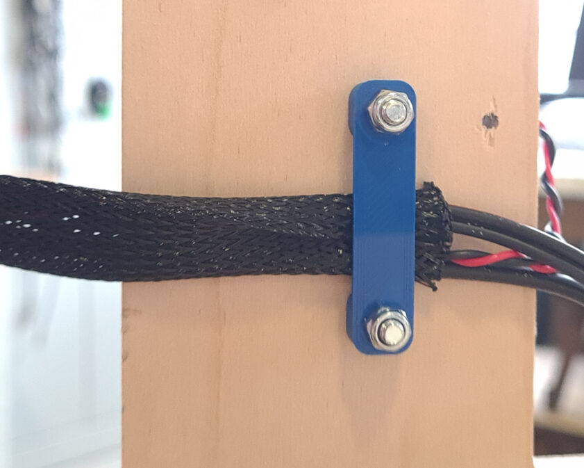
Lastly, the cable routing along the frame to the electronic parts and between them must be addressed. For this, I again designed small clips with "U"-shaped structure where the opening is 12.55 mm wide, equivalent to the frame material thickness. On its end, two screw holes are created to be able to mount it to the frame.
fIVE of these parts were fabricated from blue PLA using an Ultimaker S5 with the "Normal - 0.15 mm" profile and default settings. To mount these, 4 mm holes were drilled at the desired positions, the cables were placed on the side, then the routing parts were mounted over them and lastly, M3x20 bolts and nuts were used to fix their positions.
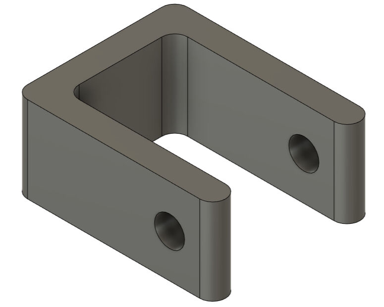
Designed Parts for Cable Routing Along Frame
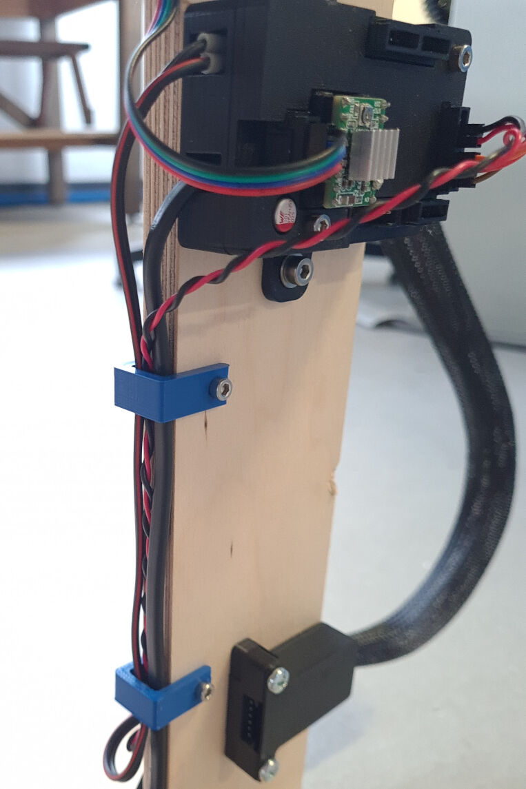
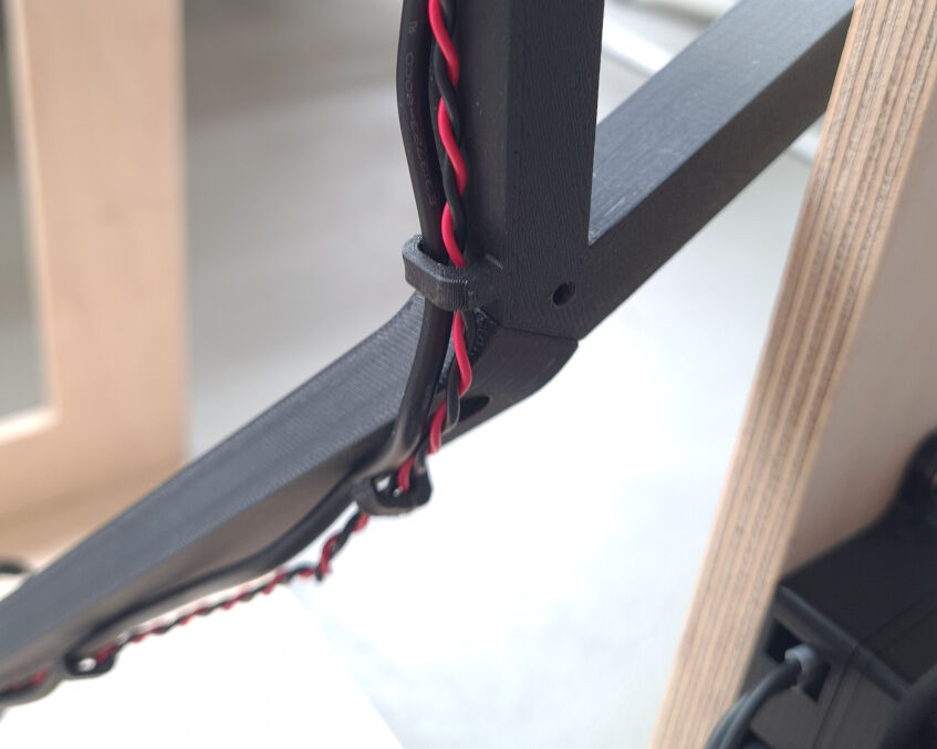
Cable Routing Along Frame at the Housing for the Main Board
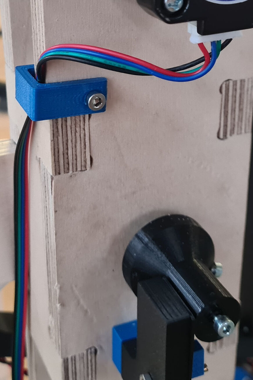
Cable Routing Along Frame for Motor Cable Leading Downwards
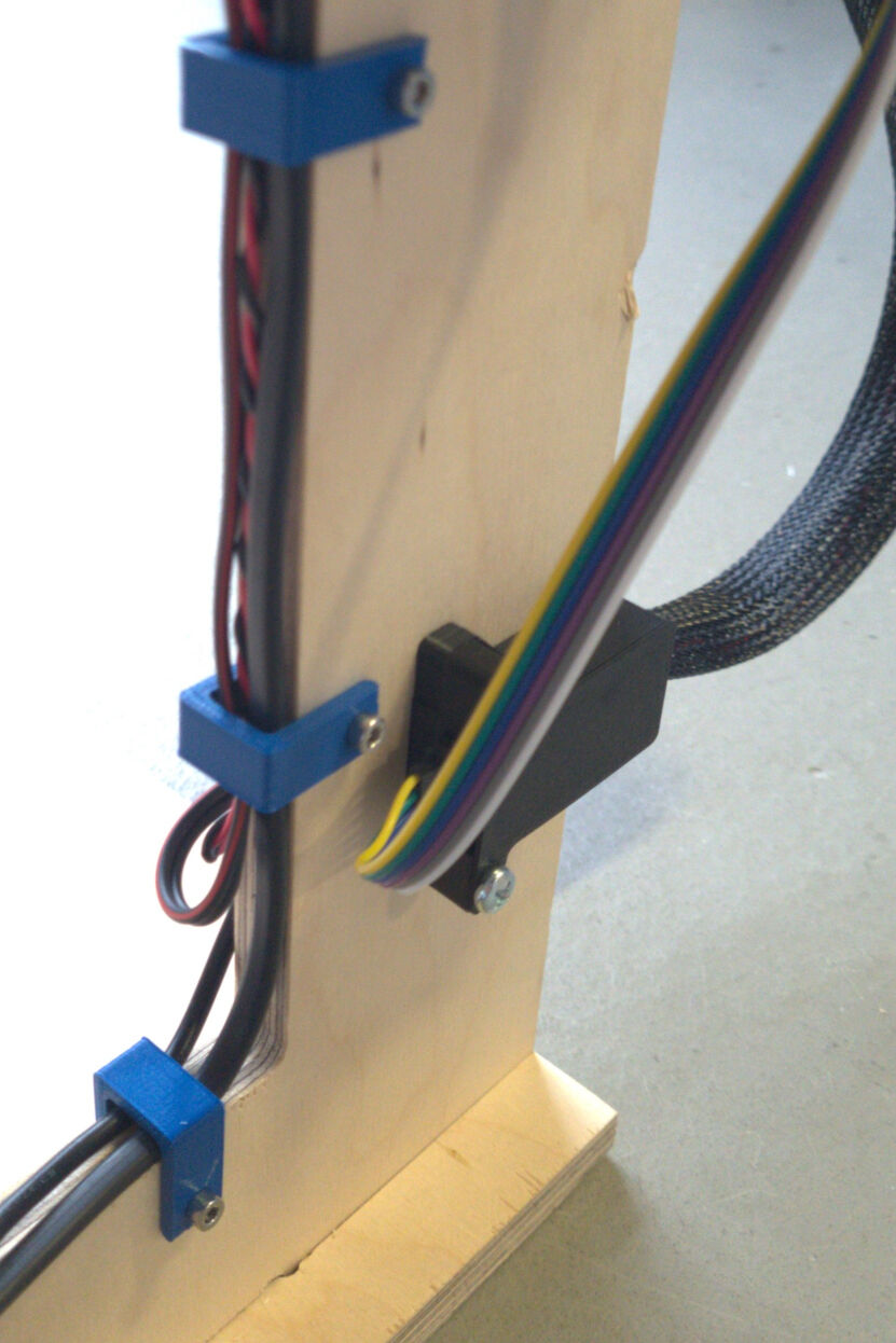
Close-Up on Cable Routing Along Frame in the Bottom
Complete Results from System Integration
With the cable routing, the system integration was complete. However, I still think it looks a bit messy which may be due to the jumper cables. They are relatively short causing the lead directly from the main board to the FTDI module or the hall sensor.
In future, I would like to use longer jumper cables which I can route accordingly. Additionally, I would also like the cables to be invisible rather than fixed at certain places. However, this required also a substantially larger design and part which compromises the fabrication time.
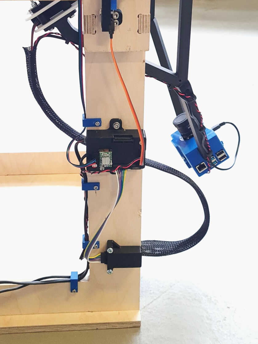
Complete System Integration
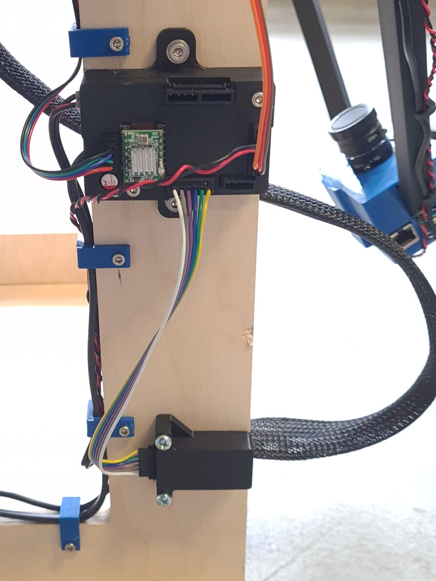
Close-Up on the System Integration
Design Files for Download
- JST Connectors (.f3d): 3D printable JST connectors in male and female version for three, four and six pins
- Housing for Raspberry Pi Camera (.f3d): Two halves of the housing to enclose the Raspberry Pi board, camera module and lense
- Housing for Hall Sensor (.f3d): Housing and attachment to the frame for the hall sensor
- Housing for FTDI Module (.f3d): All parts assembled for the housing of the FTDI module
- Bottom Part of Housing for Main Board (.f3d): Bottom half of the housing for the main board
- Top Parts of Housing for Main Board (.f3d): Parts for the housing of the main board on top of the board including the JST connector parts and cover as well as customized female JST connectors
- Cable Routing (.f3d): Part for attachment of sleeve to frame and cable routing parts along side of the frame