Week6: Electronics Design
For Electronics Design I finally have the chance to start working on my final project. For this week we need to design a “Hello World” PCB …
The final project will be a musical instrument. For “output” week, I wanted to experiment with generating sounds using the digital-analog converter pn the ATTiny microcontrollers.
In the datasheet of the Attiny412 I found it had a Digital Analog Converter built into the IC. Regular Arduino’s never had this before so I took this discovery as an opportunity to learn more about it. I wanted to generate audio waveforms that were different from the standard block-wave tones almost all microcontrollers can make.
 |
 |
|---|---|
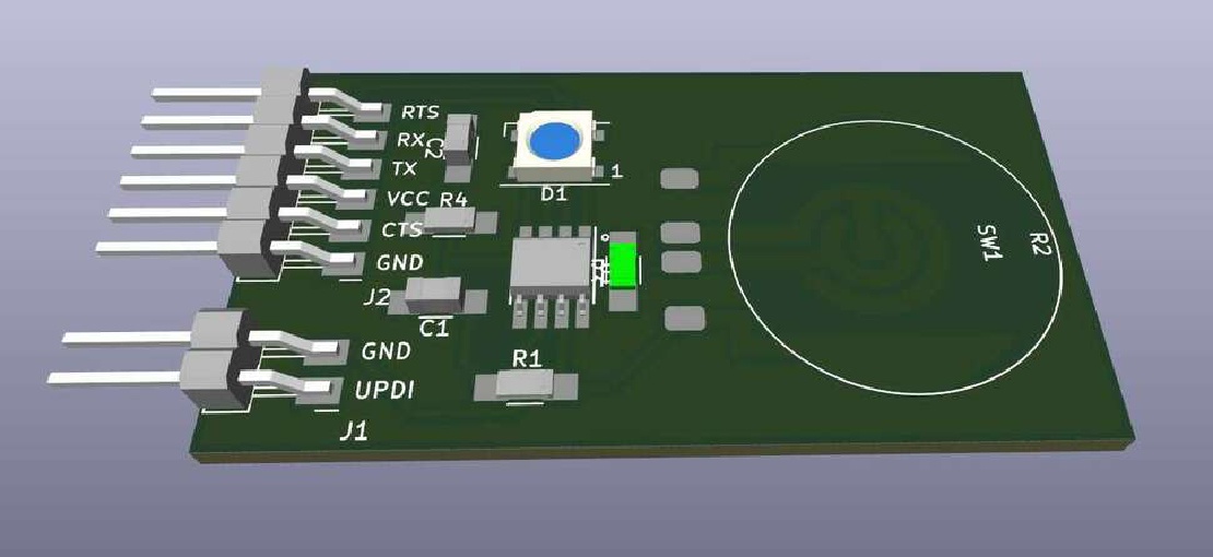
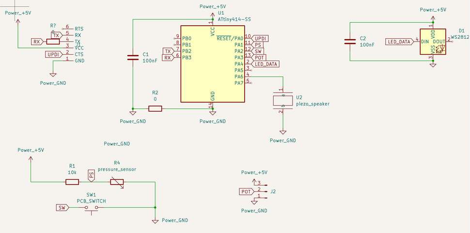
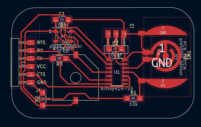
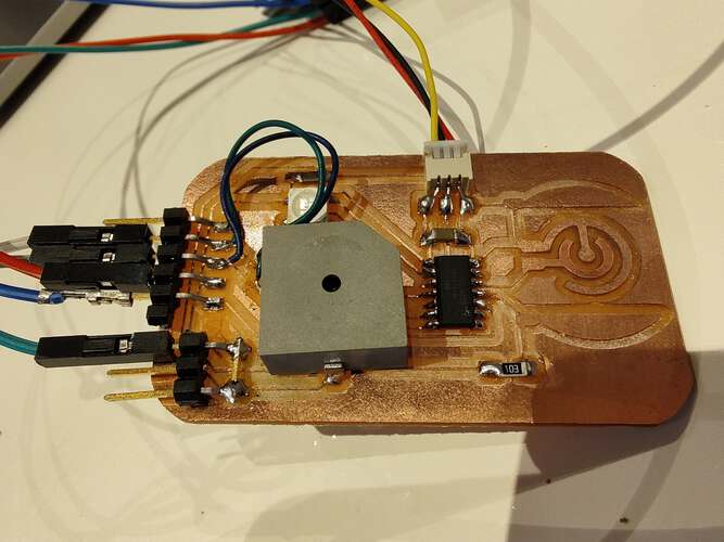
| The schematic of the speaker board | The PCB, with a pressure sensor, a button and also an analog port for a potentiometer |
 |
 |
|---|---|
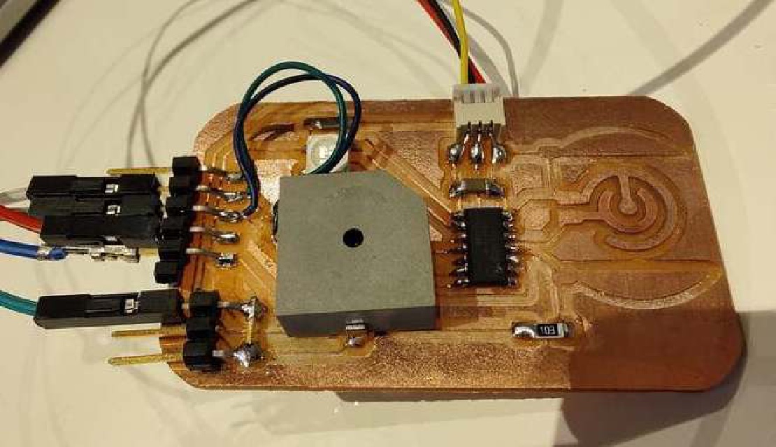
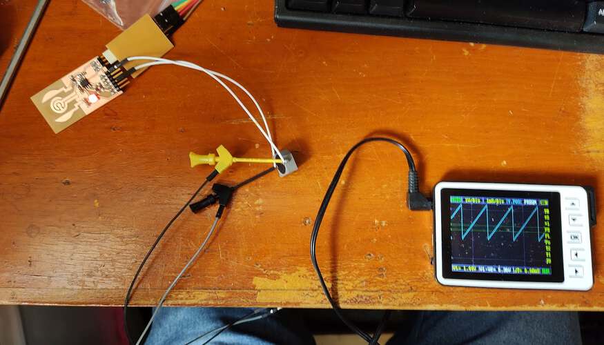
| The PCB contains an SMD speaker. | The DAC works and can output sawtooth waves. |
To support more types of waveform would require more memory than a small chip like the attiny412 can provide. A sine wave for instance uses a lot of memory and processing power since it relies on floating point operations. I experimented with a method to generate sine waves with limited computational abilities using a very simple numeric method to solve linear differential equations. This could then be used to simulate a spring. Springs are great because, when undampened, the output is a perfect sinewave, if the phase of the sinewave is of no interest (which it isn’t in this application). In the simulation below you can play around with the spring to see what waveforms it can generate.
| Spring simulation | Play around with the sliders to change the spring behavior |
|---|---|
The following code was used to simulate the spring in JavaScript. It is based on an Euler approximation of Hooke’s law.
void updateSpring() {
  a = (-(x - xRest) / k - v / c);
  v += a / 100;
  x += v / 100;
}
The challenge was to get this to work with a microcontroller using only fixed point integers (no floats). I managed to get it to work somewhat but it needs quite some tweaking still.
Simulating springs can server a lot of purposes for sound synthesis. It can be:
Any of these should not need more than 10 bytes of memory. Unfortunately I didn’t have time enough to explore this concept.
Later in the cycle I used a smaller version of the SMD piezo speaker for a sound project for the Networking and Communications week. This project used the tone library. I needed a way to convert Midi notes to frequencies. First I sought to do this in the attiny using only fixed point variables. Later I decided it was much easier to use floating points on a faster device, such as the ESP8266 and then let the Attiny play the frequency. The conversion can be done using the following code:
#define BASE_FREQUENCY 440
#define BASE_PITCH 69
double toFrequency(double incoming_note) {
  return BASE_FREQUENCY * pow(2.0, (incoming_note - BASE_PITCH) / 12.0);
}
To light up the buttons on the “feib” instrument I used WS2812 LEDs, also called NeoPixels. I used the NeoPixel Static library, as the standard library didn’t play well with I2C.
| I cut a strip of NeoPixels to reconnect the using wires | A string of LEDs mounted on backplates, with holes for strain relief. |
The LEDs needed to be cut up and resoldered because the needed to be part of a new enclosure for the buttons on my device. The original button enclosures were not at all translucent.
 |
|---|
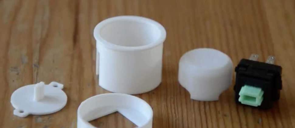
| The new button enclosure consists of a shell, an LED backplate, a top cap and a bottom cap. |
 |
|---|
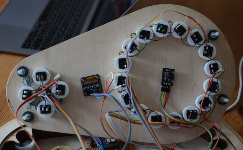
| The backside of the top panel of the “feib” device. The LEDs in the buttons are all linked together. |
The “feib” device contains an OLED display to show the state of the device. I found an OLED display that was small enough.
The only library I could find to work with the display ran on an ESP8266.
| The OLED display is used to show what chord progression is selected |
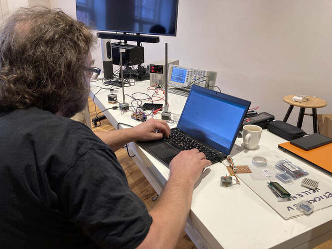
For the group project we measured the power consumption of an Arduino with a motor shield and three steppermotors. The Arduino ws programmed to make the stepper motors perform a movement for 20 seconds. The motors were powered using a lab powersupply of which we could control the voltage. The Arduino was powered with 5v.
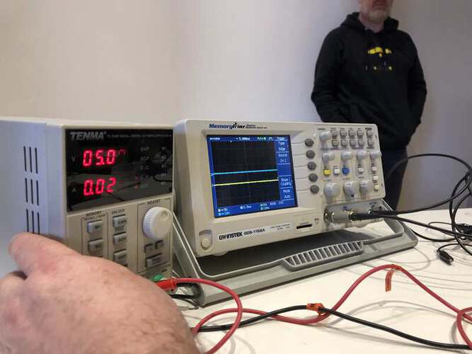
The idle current draw of an Arduino with a motor shield turned out to be 0.013A. Powering a motor without moving it was alomst seven times higher at about 0.08A. The motor in motion drew 0.101A of current and 0.116A when obstructed. All of these tests were done powering the motor with 12v.
 |
 |
 |
|---|---|---|
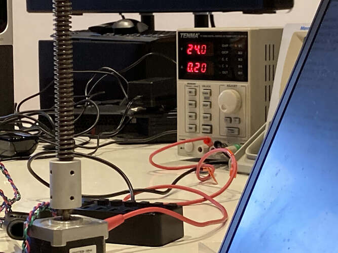
| The setup, containing an Arduino with motor shield and several stepper motors. | The scope was used to show the change in current over time, using a shunt resistor in parallel. | The current consumption could be read from the lab power supply |
For Electronics Design I finally have the chance to start working on my final project. For this week we need to design a “Hello World” PCB …
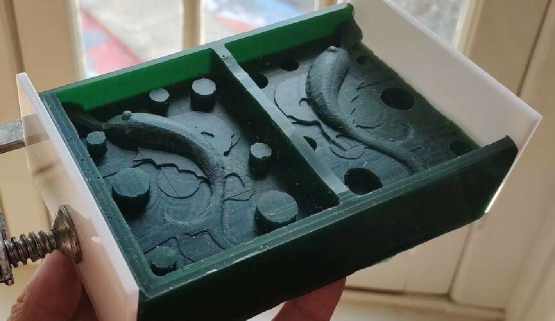
Molding and casting is very interesting as a production technique because it allows you to work with a large variety of materials and you can use it …