
Empathy:
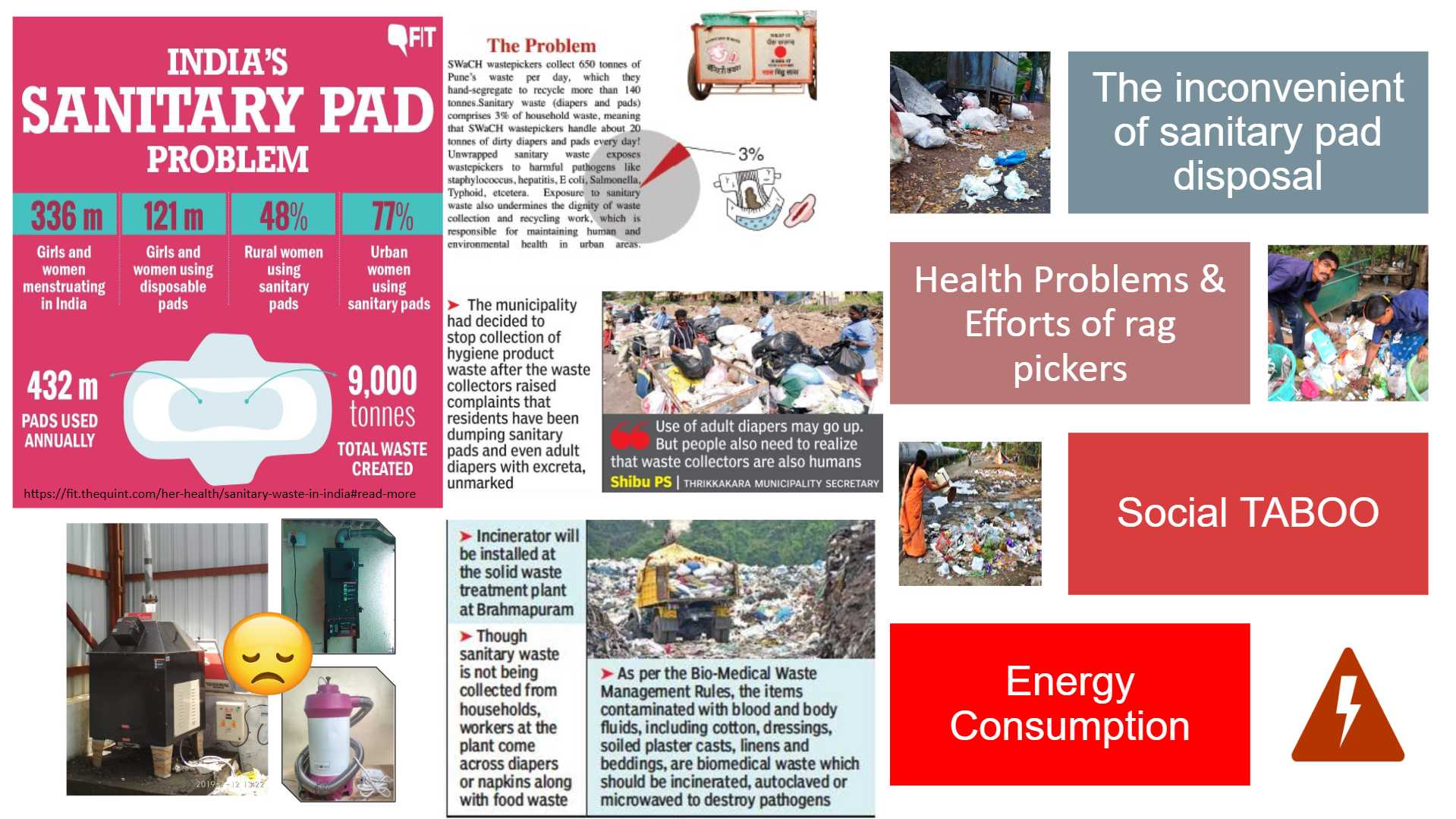
Empathy of sanitory pads problem in India.
-
Here is some data from known publications and organizations in India on the sanitary waste disposal problem.
- According to the clean India journal data,432 million used pads are generated annually in India, approximately 9000 tons of Sanitary waste per year.
- According to “Swachh” Servey 2018. Considering only Pune city generates around 650 tons of waste per day. Out of which 3% are sanitary waste .which is approximately 20 Tons and it is handled by many rag pickers.
- Menstrual health alliance India states around 45% of people are throwing their sanitary waste along with household garbage. That exposed Sanitary napkins pass great health risks for the rag pickers due to harmful pathogens.
There are some positive steps taken by the Indian municipal corporation by installing Centralized Electrical Incinerators at women's centres to deal with this problem. But still, the ground reality is the same all through the incinerators are installed but many of them are not in use due to improper maintenance and higher energy consumption many of them are not in use.
Define:
This project is basically focusing on the disposal of used sanitary pads. For that, I propose an LPG base sanitary pads Incinerator for rural and urban municipal corporations and hostels.
Under the umbrella of sustainable development goals. This project covers the “Sustainable cities and communities ” problem.
-
In the problem statement, this project is trying to focus on the,
- The problem of In convenience of sanitary pad disposal.
- Social TABOO related to sanitary pads.
- Helt problem and efforts of rag pickers
- Energy consumption of the existing products.
To solve this problem statement during my fellowship at Vigyan Ashram Pabal. I designed an LPG base Sanitary napkins Incinerator of 5 Sanitary napkins capacity. But this system was only limited to a smaller quantity. So in this project, I am trying to scale up the design up to 60 pads per batch.
Ideate:
To Ideate the bigger version of the project. I first want to Introduce the last version of the 5 pads incinerator Which will you find on my
principles and Practices.
principles and Practices assignments.
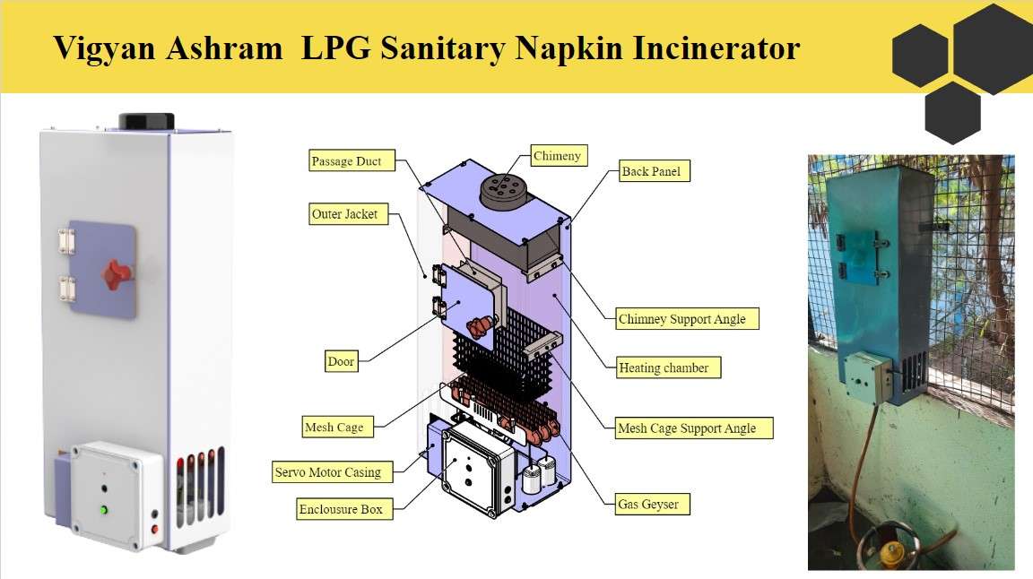
5 pads incinerator vergino.
Concept of the Working:
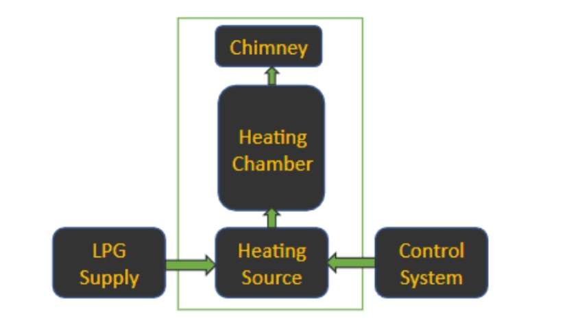
Concept design.
- The overall conceptualization of this project will be the same as the previous one. It will consist of a manly 5 units.
-
An automated LPG flow supply.
-
A heating Source to burn the Pads.
-
Heating chamber to insert the pads.
-
A control system to Automize the system.
Project Visualization and CAD.
After a long brainstorming with my friends and DIC members. I came to this conceptual design. As shown In below picture. And Started designing a CAD model . I designed several models and came to this final design as follows.
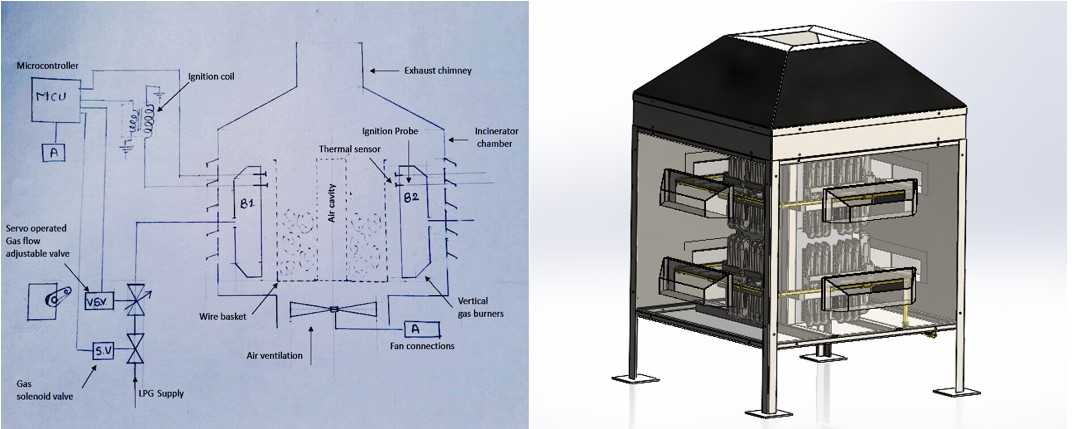
Concept drawing and 3D model.
- As you can see the system Is going to consist of an MS sheet metal enclosure which will take the role of a heating chamber.
- An Exhaust chimney for exhaust of flue gasses and providing a natural draft for airflow during combustion.
- A vertical multi-burner set in a core of the machine acts as a Heating source. For combustion of the pads.
- A mash cage basket for holding and inserting the pads in the combustion chamber.
- And A copper pipeline structure for LPG supply towards the burner. As you can see in the picture.
3D CAD model designe using Solid Works:
I designed the hole modelling in Solid Works. I took the help of prasad Patil, my friend, from DIC in the process of CAD designing.
CAD Animation of Incinerater.
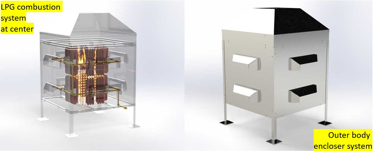
3D rendered models of the system.
Prototyping and Fabrication :
Plasma Cutting:
I fabricate my project design in MS sheet metal . Because it provides a good strength to my project. For that, I use a Plasma cutter In our fab workshop. As this was a big task I took the help of some of my friends to complete this job. I fabricated some of the parts in my wild card week such as the Ashtray chimney for the exhaust system etc. most of the parts I fabricated earlier before wild card week. As I have handled this machine sometimes in DIC.
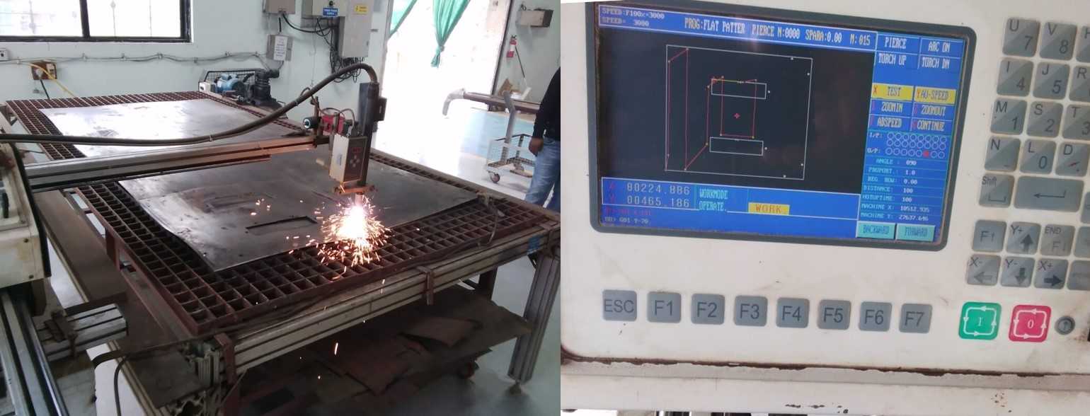
Plasma cutting.
Plasma cutting process.
Panting and cover protection:
As the hole Enclosure body is going to hold the Fire flames . I decided to apply a layer of Red Oxide through the inner side of the Hole body. and for the outer Body, I apply a high-temperature Heat Resistant Paint which can sustain temperatures above 800 degrees celcius.
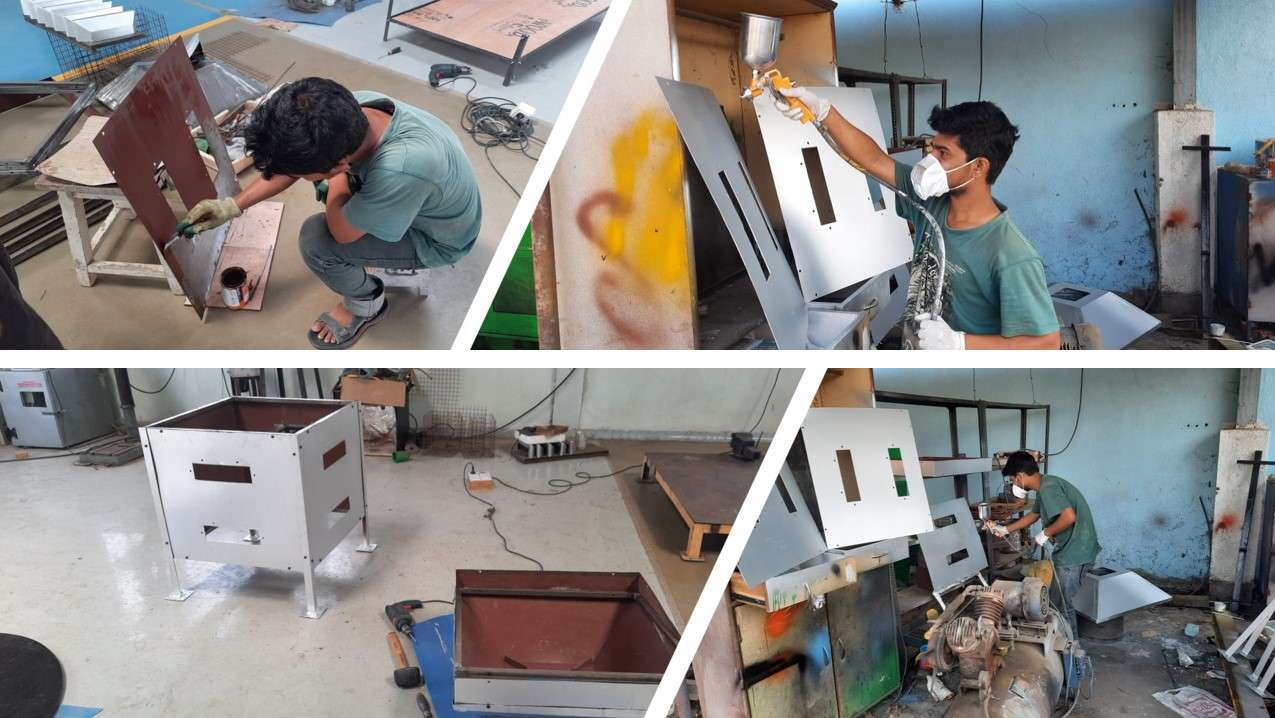
Panting with heat resistive paint.
Sheet metal Fabrication:
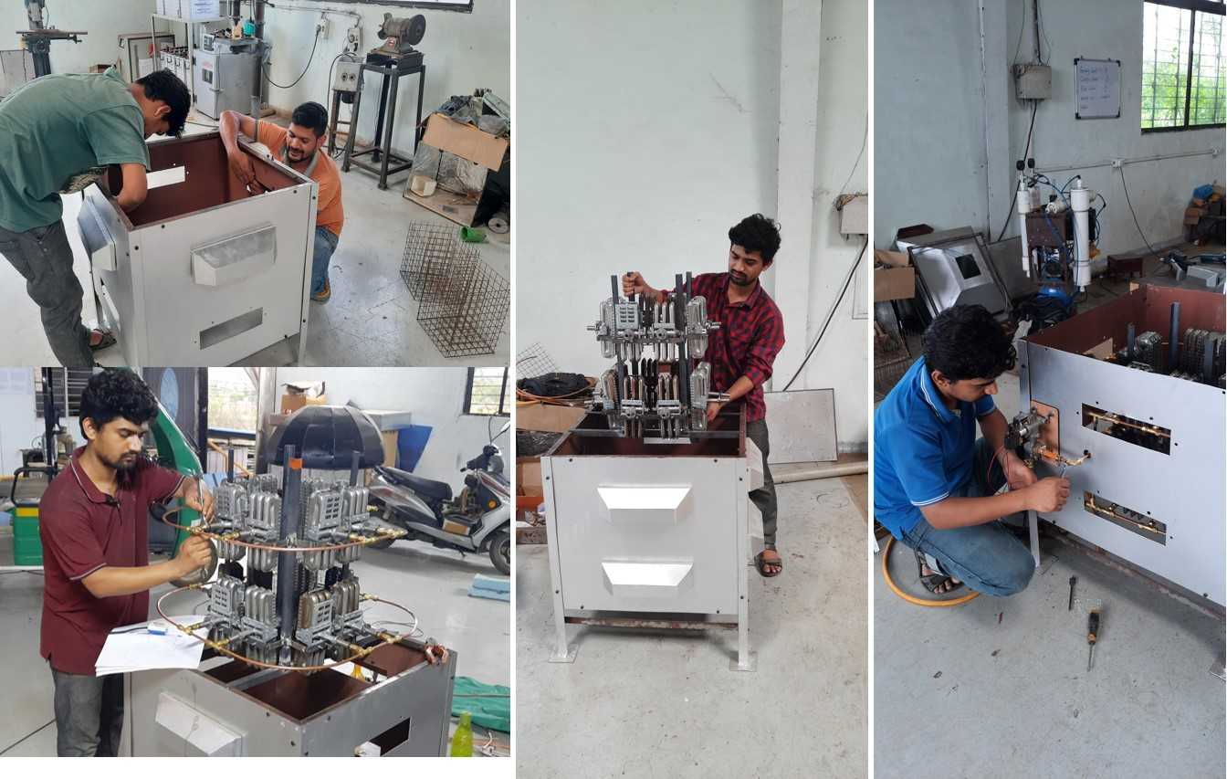
After plasma cutting. I did some workshop work . Such as machining, banding and welding to give shapes to the Encloser body and Some of the MS systems. I fabricated a Mesh cage basket ,Encloser body, chimney and Airwentelition fins, ashtray etc. I did some of this work in wild card week too
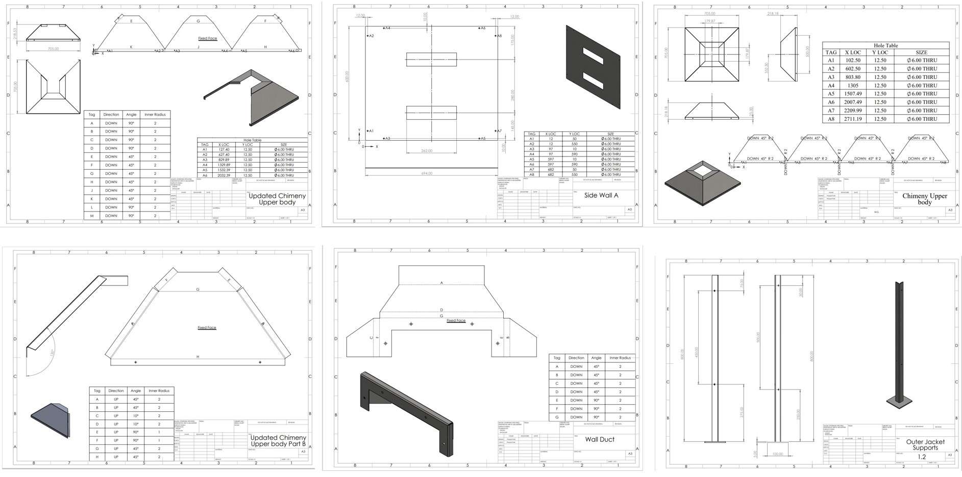
Drafted drawing of sheet metal work .
This are some Drafted drawing of Sheet metal components from my project.I provide detail drafted drawing PDFs in Sorce files
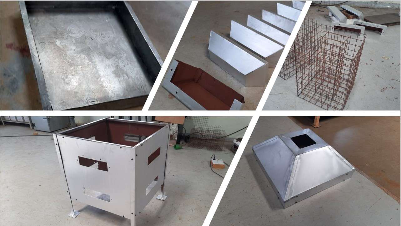
Sheet metal Components in my Project.
I also designed and fabricated a Flange design for connecting the copper gas pipe to the burner assembly at the workshop in those days. For that, I use a semi-automated lathe machine in our workshop. I took the help of Ghansham, one of my friends Who works as a fabricator in the Vigyan Ashram, for guidance. We purchase the same flanges from outside as we need this for each burner in the combustion chamber showing our flange as a sample one.
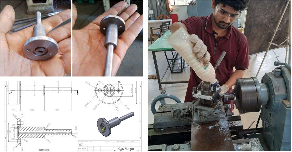
Flange design for connecting the copper gas pipe to the burner assembly..
Fabrication of the combustion chamber:
The combustion chamber in my project mainly consists of two parts. A multi-burner vertical set which consists of 16 burners each. I use the burner from the gas geyser system. Same I use In my first version. And a copper pipeline structure to flow the LPG to Each burner. We took the assumption that the commercial LPG l cylinder will provide the enuff press on the bases of some experiments and private work. We haven't done any CFT simulation for this. This will be a future part of this project.
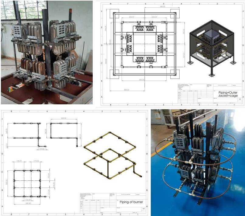
Combustion chamber fabrication.
Assembly of System:
Finally after fabricating everything in my project. we assemble the whole system using standard fasteners. I designed the system in such a way that it will be easy to transport. Below is the drafted drawing of the assembly.
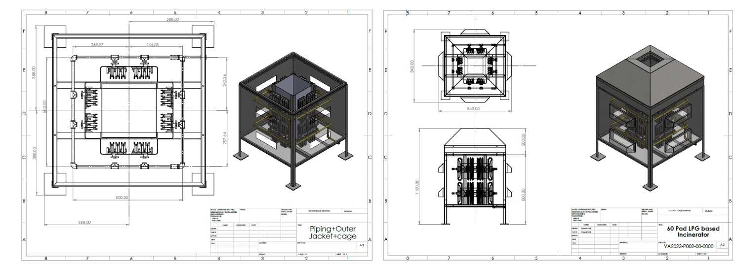
Drafted drawing of assembly .

Assembling all components in system.
3D printing:
I decided to 3D print a small Handel for the Controle panel box. As there was nothing as support to open it. I design a simple handle design using Solid works and create the g code using factory works slicing software.
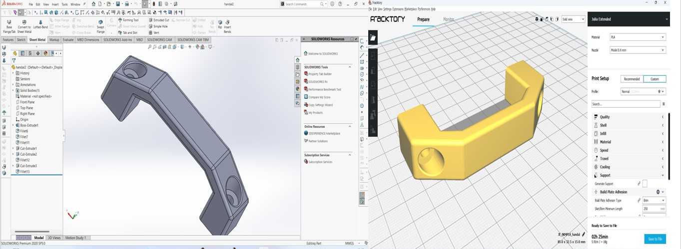
3D designing and G-code generation.
3D printing .
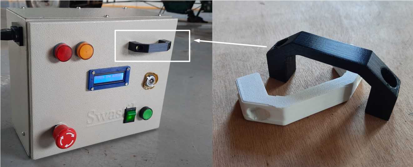
3D printed handle for control unit.
My first print gets offset. So I print another one using PLA as printing material. Which then I fix on the Box.
As it is a long time for me to use the 3D printer. I refer to my
3D printing week
for a guideline.
PCB Board design and Fabrication :
Unfortunately, I short my last final project board V2 design while testing the integration of electronics for the project. And ATtiny 1614 stock got empty .So I decided to use another microcontroller. As I refer to my embedded programming week. The more similar microcontroller to ATtiny 1614 that is ATtiny 3216 it has the same pin numbers and some excess flash memory 32kb and 20 pins than ATtiny 1614.Although this does not affect my board design due to there similar Pin configuration and same class.So I use it and design my final project board V3 design.I also replace The IRF540ND N-type mosfet with new SMD one 50N06 N-type mosfet slightly better than it and remove relay pins and replace them with a Indicator(LED) pins for Body temperature indication. ATtiny 3216 Pinout comparison with ATtiny1614 .
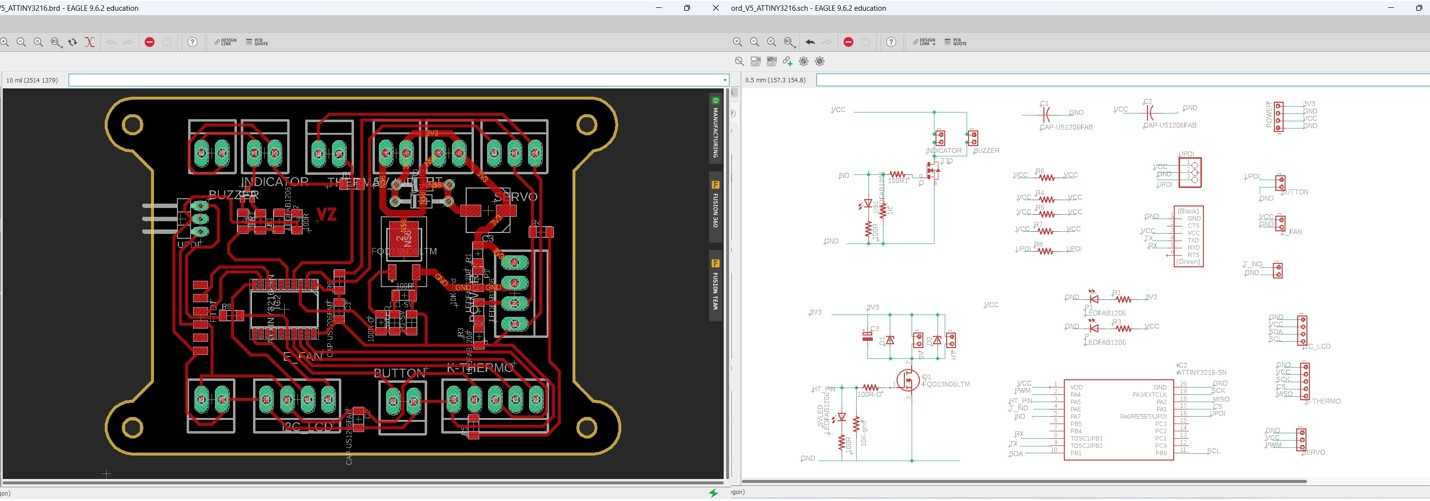
Final board Scametic design.
Final board PCB Milling.

ATtint 3216 Board.
Please refer to my assignments page from Output devices and Embedded programming. for more details.
Firmware explanation:
I write the firmware in Arduino.Basically this firmware code is derived from individual codes I use for the output and input assigment.As my device is doing multiple tasks at a single timing.I divide my Code in 6 functions to make it easy to understand as follows.
- Configuration.h_Incinerator
- H_t_Writing
- LCD_Counter
- RESTART
- servo_
- THERMAL_IND
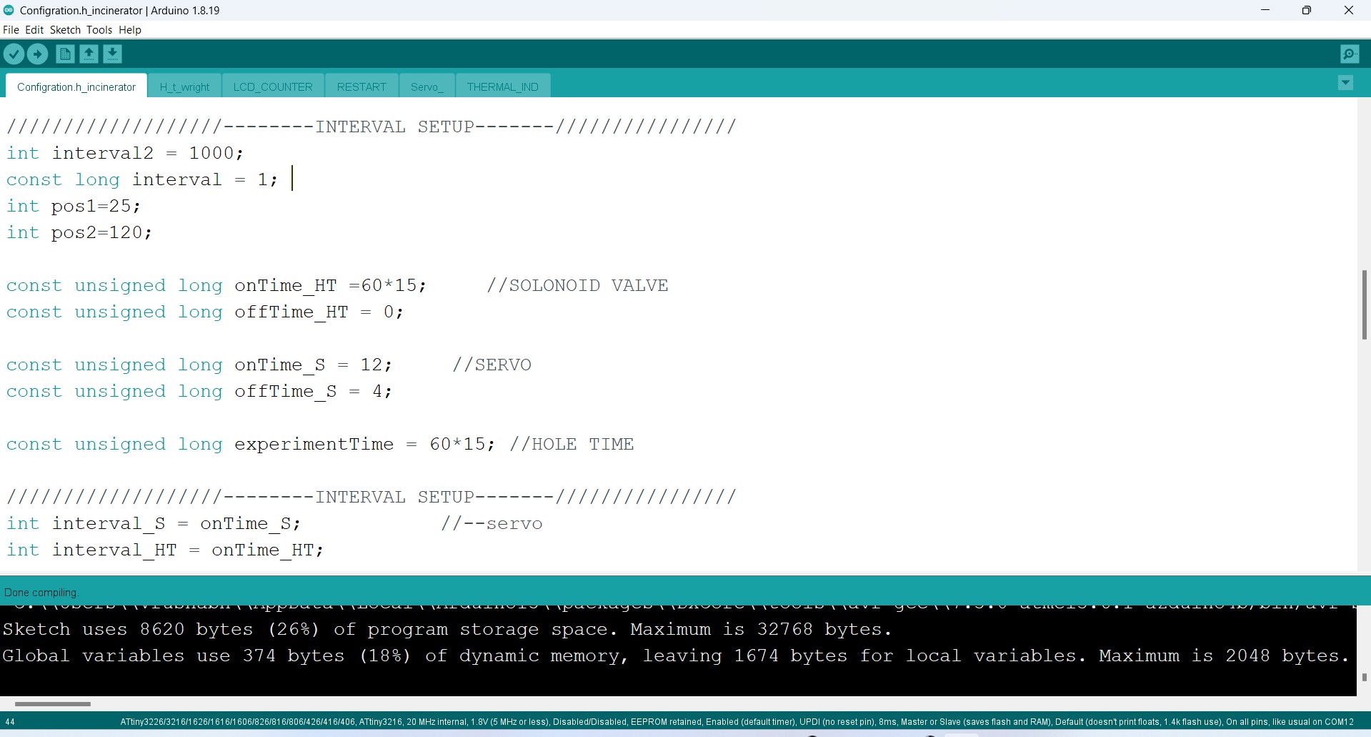
Incinerator Firmware .
-
Configuration.h_Incinerator consist of void setup() & void loop() function .all the setup and defining of input and output devices are given in this part.you can change the values of and timing of Gas supply by simply changing values in INTERVAL SETUP section in program. void loop() consist of flag logic which call the other functions when the push button is press.Also it call individually the void T_p() function to set alert and show temperature all time whenever program startes.
-
H_t_Writing consist of void HT_() function .which trigger the mosfet on condition.It consist of logic which uses currentMillis_HT ,previousMillis_HT interval_HT, varible to high and low the boolean value of HT_state variable using millis() function.the interval value can be set in the program.I use this logic for all functions and avoid to use delay() as it will stop my program in middle and I can't get accurate countdown timing.
-
LCD_Counter consists of void LCD_COUNTER() function which displays the countdown on LCD display.It also turns LED and buzzer beeps per second.I use a simple mathematical function to convert millis into seconds and minutes and print it on LCD display.
-
RESTART consists of void Reset Function() function.which restart the function after completing the one cycle of count.i.e when counter comes to zero.It also turns off the mosfet by which ignition and solenoid gets turned off to stop LPG supply.
-
servo_ consist of void servoread() function.Which semilery-like mosfet function moves servo to pos1 and pos2 which minimus and maximize the fuel supply during program.this operation is also performed by interval as per void HT_() function.
-
THERMAL_IND is consist of void T_p() function.Its get call soon as the void loop() function.Its read the value of K-type thermocouple and print temperature value in degree celsius on LCD display.It also Turn on the Alert Red indicator LED on Panel if Temperature >49 degree celsius to prevent accidents.
Electronic Intrigration and testing:
This is not only the Electronic Integration but also the Testing of my Integrated arduino code testing .As I already tested this devices in my previous week assignment (Input and Output devices) some how.Following I have demonstrate the table assembled testing of all electronic in my project system.I use the Same codes from output and input devices and integrate them in an algorithm as demonstrate in the following video.
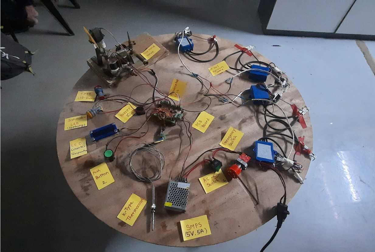
Electrons table top testing setup .
-
Algorathem:
- First the user will power on the AC supply.
- He/she will switch on the power supply by turning on the green button(Emergency switch must be open).
- LCD display will print “LPG INCINERATOR ” initially for 3 sec .then it will ask for “Press the button” by printing on screen.and symentanusly show the Enclosure body temprature.
- Then user will press the green push button to start the program.(use one push on/of cod from input devices) it will start by busser bip and a yellow light indicator blinking.
- As soon as the button gets pushed .The program will call the ignition function(HT) to turn on the N-type mosfet.which result switching the Ignition circuits and Solenoid valve.
- Same time program will also call the Servo function which will move the servo in an interval of 4:12 second for 0-120 angle(I will set it later depending on experimentation).To make flame up and down (To inclose and expose the pads by fire).
- Simuntenesly the program also calls the LCD function which is showing all characters on Display.and a Counter clock function displaying the remaining time of incineration operation.
- Lastely the program will call the Restart function when the counter reaches Zero.
- Throught the program a T_P function i.e a enclosure body detecting function is going to be run simentanesly. Which will show the body temperature on display. And also Provide an alert if temperature detected by K-Type thermocouple is > 49 degree celcius.
Following is the video of demonstration algorithm and Electronic Integration and testing of system.
Intrigration of all electronic in project.
Please refer to my assignments page from Output and Input devices for more details.
System Pacakiging :
Control Panel wire routing:
After confirming everything in working properly.I Enclose my controller ,SMPS,emergency switch,indicator switch ,LCD ,buzzer and,LED indicators and other control devices on a Electrical Enclosure box.For that I took help from Shanker who is expert in panel fitting.He explain me the techniques of wire routing and how to simplify the wiring process.
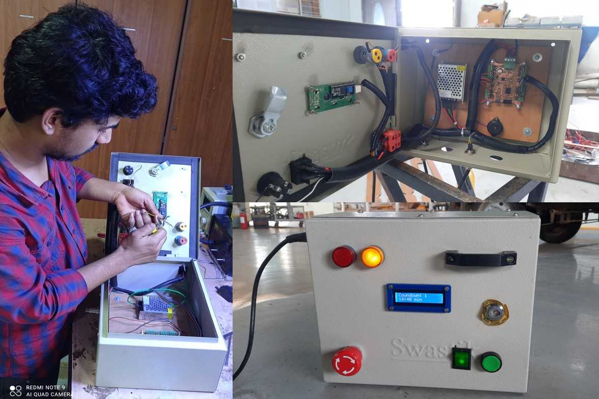
Control panal wire routing.
Final Code uploding:
Control panal testing.:
Control panal testing.
System Electronic mounting:
Project contain 2 main electronic assembly one is Gas flow automation system and another is LPG gas ignition system.for connecting them with the control panel box.I use metal connector and PVC multi core wire of 4 core (vcc,gnd,Gnd from mosfet ,PWM servo)and 3 core(SCK,MISO,CS for K-type thermocouple) respectively.I use a plastic screw connecter and the machine end to distribute wire to various components.
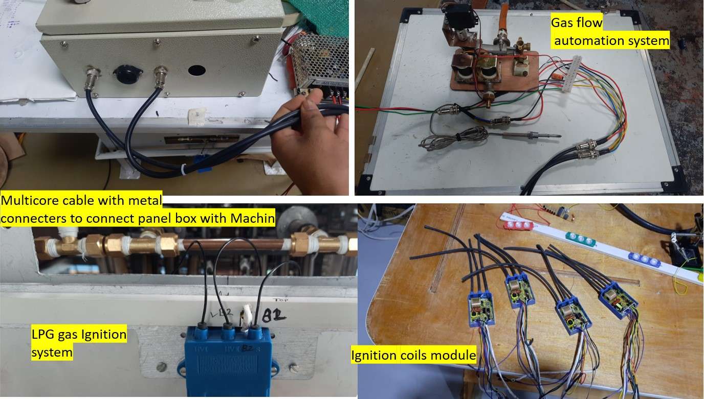
Mounting of Ignition system and gas flow automation system.
For mounting the Gas flow automation system on Encloser body .I use a 5 mm Plywood sheet and cut it on LASER cutter to make separation from hot surface of metal enclosure.(Note:it's untouchable hot for humans and reasonably sustainable by plywood).
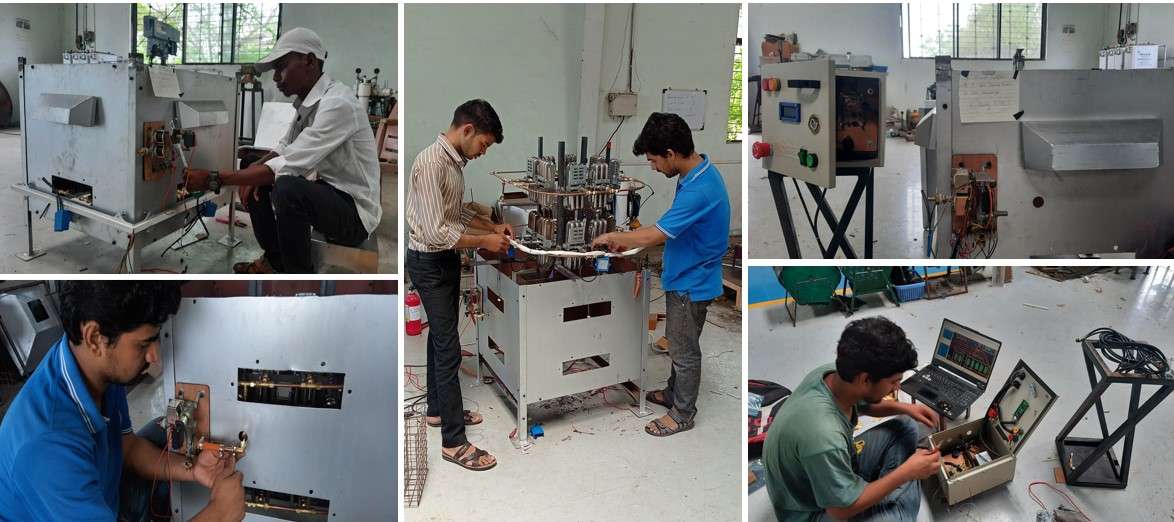
Wiring of electronic components.
I connect all the Vcc and Gnd of Ignition coil modules with a 1mm single core electrical wire (heat resistance ) and cover it with glass fiber slives . I also change the high voltage caring probs with teflon wires .and use ceramic rings if necessary nearby the burners.I put the K-type thermocouple nearby surface of burner to detect the temperature and provide alert .thank you to my friend purnesh ,ghansham,keshave,and shankar for helping me through the assembly.it was a big task.
Finishing Assembly of all system:
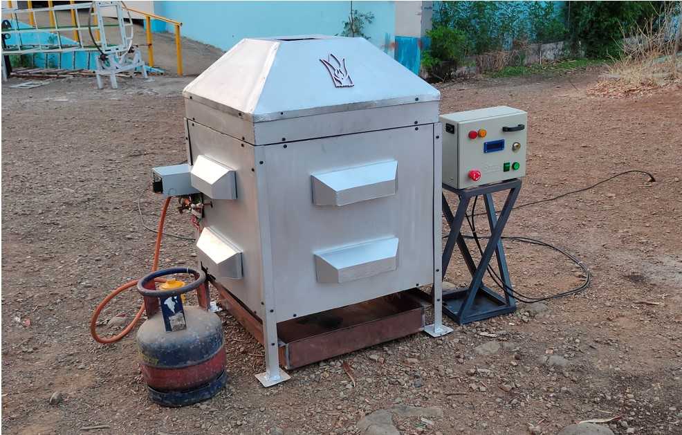
A little bit of work remains to attach the gas system ,copper pipeline with flow control valve with flexible gas pipe (use in home LPG gas system)etc.
final Incinerator Assembly.
Incinerator Assembly overview.
Testing of machine:
Finally first testing of machine after all assembly .we have limited sanitary pads to test .here is purnesh demonstrating the 1st test of machine.Every thing is working properly except thermocouple.Its not showing the proper value.So I decided to remove its function from code .there must some loose connection (a hardware related problem )which I was unable to solve at that oment.rest of all everything is functioning properly.
Final working testing of machine.
This is all the project ends for fab academy.But for real world test I have to work on it further.
Thank you for being with me throughout the page...
😀
Heroshot:
project presentation Slide.
Presentation Video:
project presentation video.
Sourse Files
Acknowledgement:
I would like to sincerely thank my fab academy instructors Mr Suhas Labade and Local Instructor Aditi ma'am for being with me through the project and I will also like to thank Mr Arun Dixit and Mr Prasad Patil for their valuable guidance. I would like to thank my team members i.e. Purneshwarkumar Sahu Ghansham Bande for their support and coordination. I will like to appreciate other helping hands from Fab academy bach meet Ashish Shende, Mr Kiran Wakchaure, Jaydeep Patel, Mr Kishor Gaikwad, Fenil Chandrana and Devesh Nair and my friends Rahul Kanojia, Rutika Ghodekar, Purushottam, Omkar, Keshav and Prasad from Vigyan Ashram for helping me in my fab academy assignments and a final project.
-------------------------------------