The task list for this week:
- Group assignment:
- Measure the power consumption of an output device.
- Document your work to the group work page and reflect on your individual page what you learned.
- Individual assignments.
- Add an output device to a microcontroller board you’ve designed and program it to do something.
Group assignment:
This assignment is about documenting what we learned in Output Devices week that includes understanding different output devices and measure the power consumption of an output device on one of the board we made as a part of individual assignment for this week.
.
Check here to read more about our group assigment.Individual assignments:
Power calculation of components in my project:
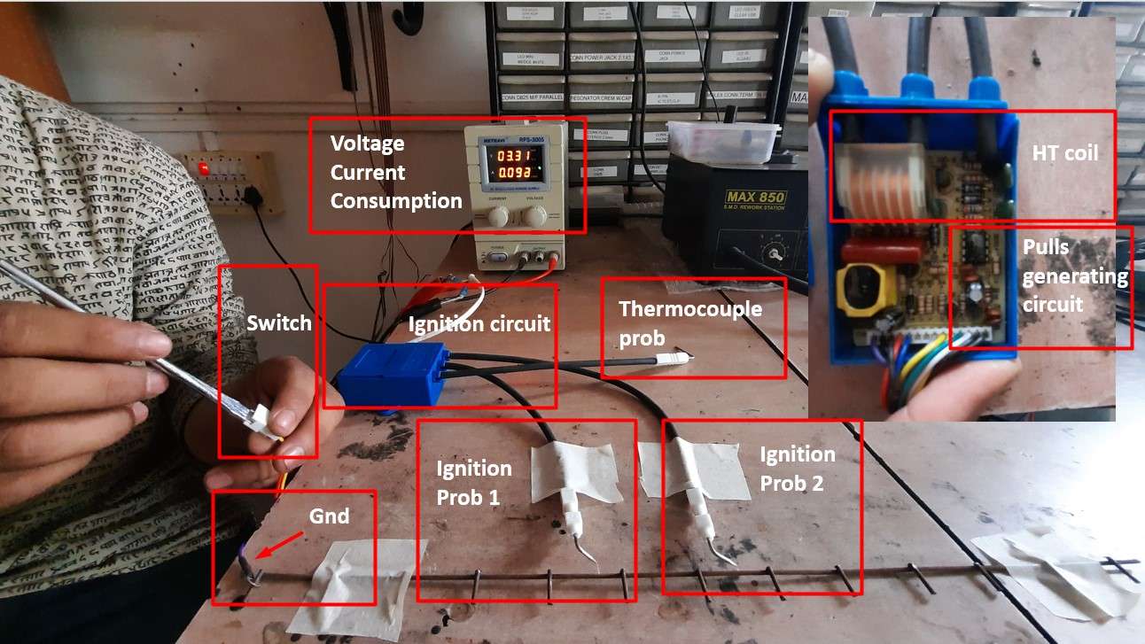
This week I decided to check the power consumption of the electric components I will require for my final project. The majority of the component's datasheet was available to me except for some of the component's gas solenoid valve and ignition circuit. To calculate their power supply power consumption. I connect them to a variable power supply unit and set the voltage as per the information on the label of the component(As the gas geyser operates on 3.3v).
Ignition Circuit:
The ignition circuit consists of an HT(High tension coil) which steps up the input DC voltage to A 13kV AC output with a very small current flow. It consists of two probes (High volt output) and a thermal sensor in it to turn off the ignition when detected fire.I bypass the switch to activate the ignition circuit.
-
Power calculation for single ignition circuit:
- Current Consumption=0.098A
- Operating Voltage=3.3V
- Power consumption=I X V=2.0A X 3.3V= 6.6 Wattage
.
Then I combine 8 Igniter circuits in parallel to see the power consumption.
-
Power calculation for 8 ignition circuit:
- Current Consumption=2.0A
- Operating Voltage=3.3V
- Power consumption=I X V=2.0A X 3.3V= 6.6 Wattage
Gas Solenoid Valve:
I also used to calculate the power consumption of the Gas Solenoid . I am using an incinerator to control LPG flow.As it is an Inductive load .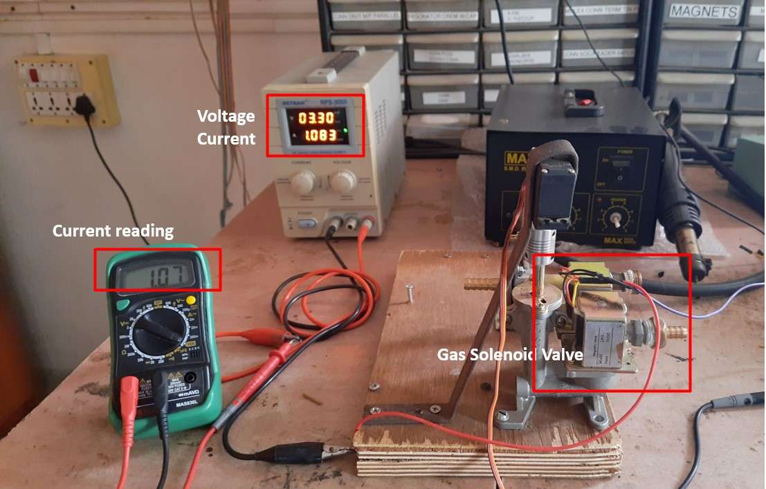
.
-
Power calculation for Gas Solenoid valve:
- Current Consumption=1.003A
- Operating Voltage=3.3V
- Power consumption=I X V=1.003A X 3.3V=3.3 Wattag
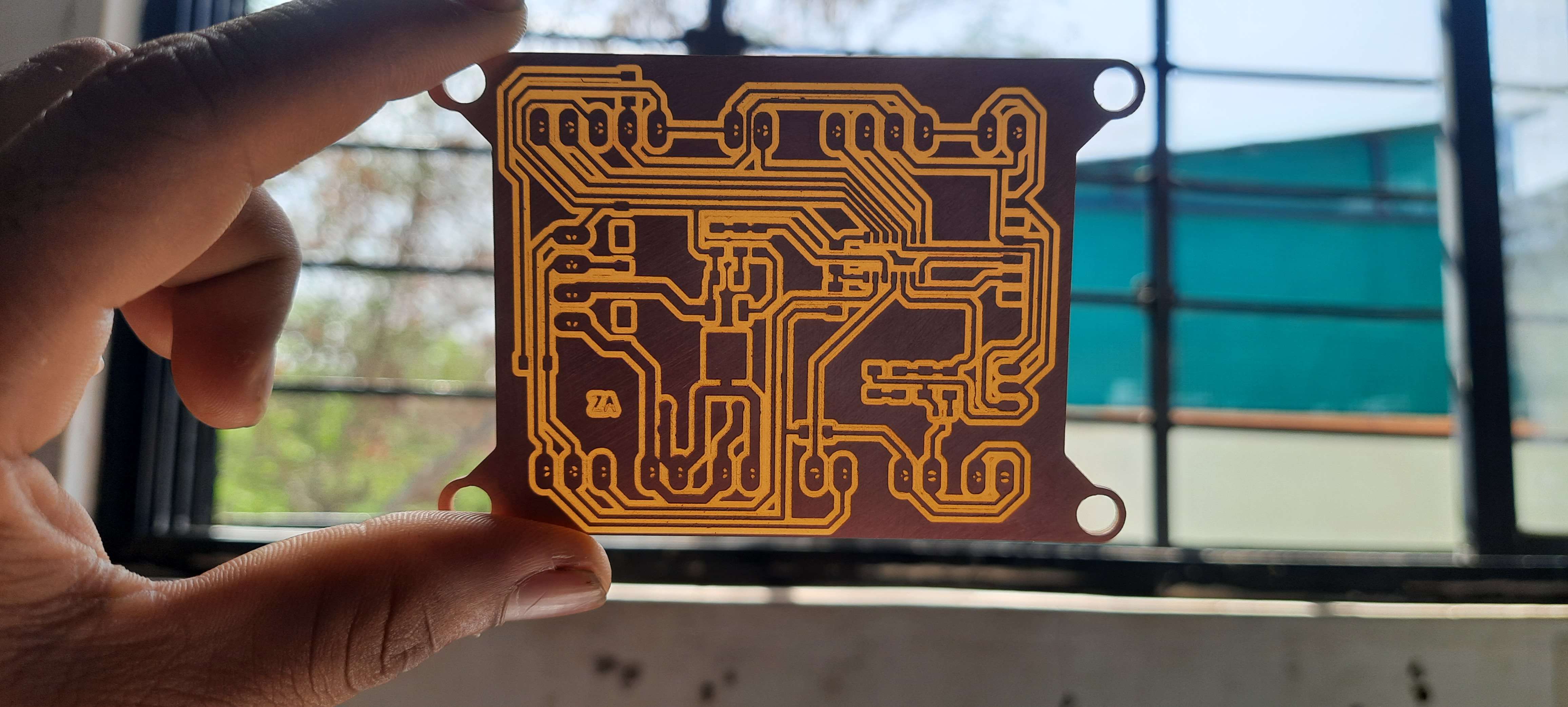
Board Design:
In last week of Embedded System assignment .I discussed about Attiny1614 and conclude is the one I am using to design my final board.To start with designing process .I read the datasheet the communication protocol in attiny 1614 ,pin out and its functionality,Power requirement flash memory etc and analyze its suitability for the electronic components an the program for my board.
ATtiny 1614 pin out.
Board piout and functionality:
After studying the Data sheet .I make a draft of pin outs and there functionality for my board as following:
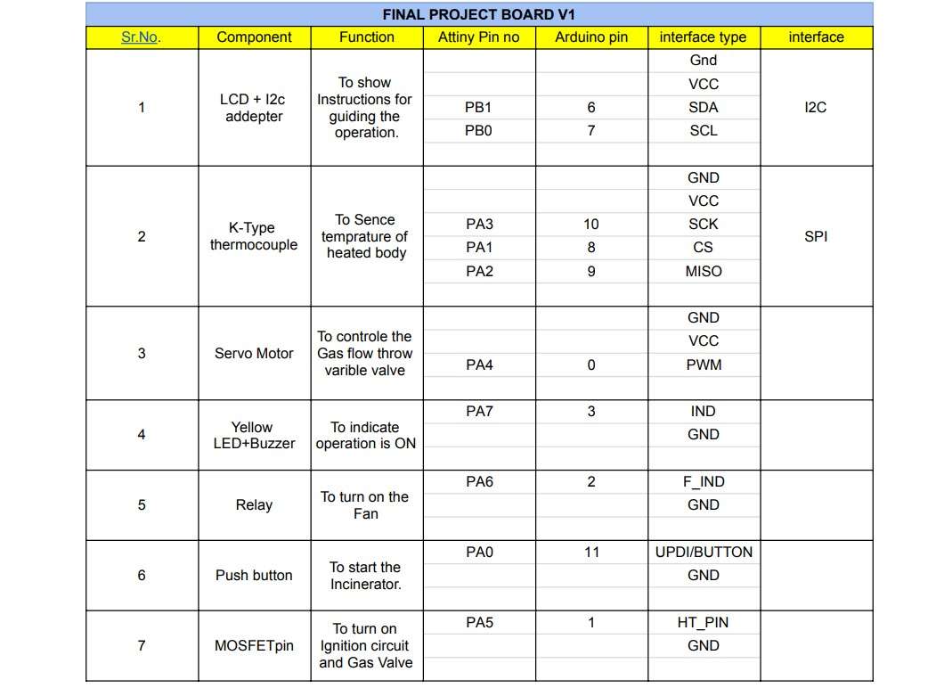
Final board piout and functionality.
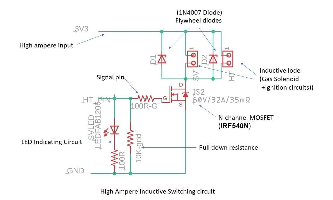
High Ampere switching Circuit:
Below is the subset of my Board schematic .Where I design a Switching circuit for Gas solenoid valve and Ignition circuit with High Ampere current.I use N-channel MOSFET IRF540N . to switch the High ampere 3.3 volt supply from externally in board.I also embed the 1N4007 Schottky diode to prevent as a Flyback diode to protect the circuit from back EMF generated by Solenoid and Ignition circuit.
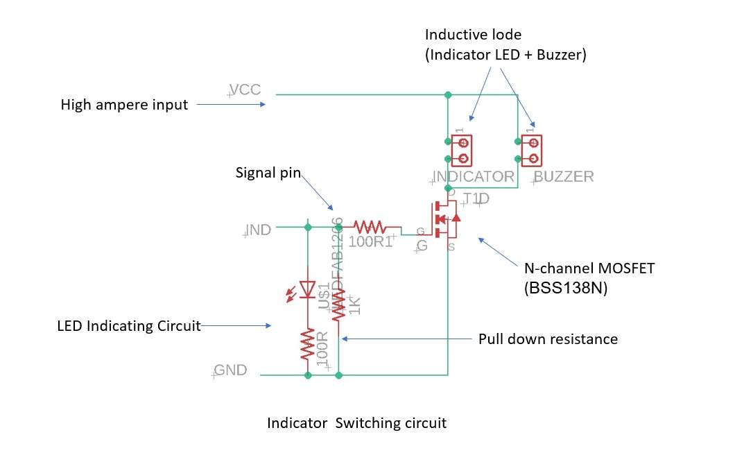
Because the digital pin out of ATriny 1614 has a limited current output(40mA).I am using another N-channel MOSFET BSS138N to switch the Indicator LED and piezo Buzzer circuit.to fulfill their current requirement.
Final Board design and fabrication:
Scametic Designe:
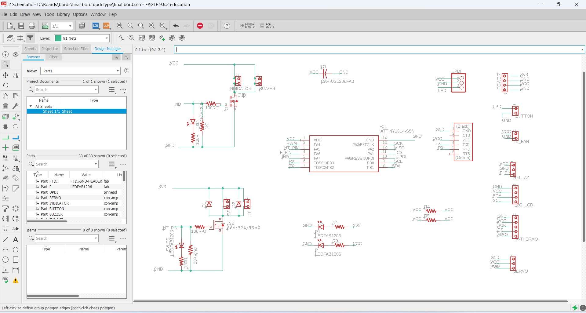
Scametic Designe.
Board design:
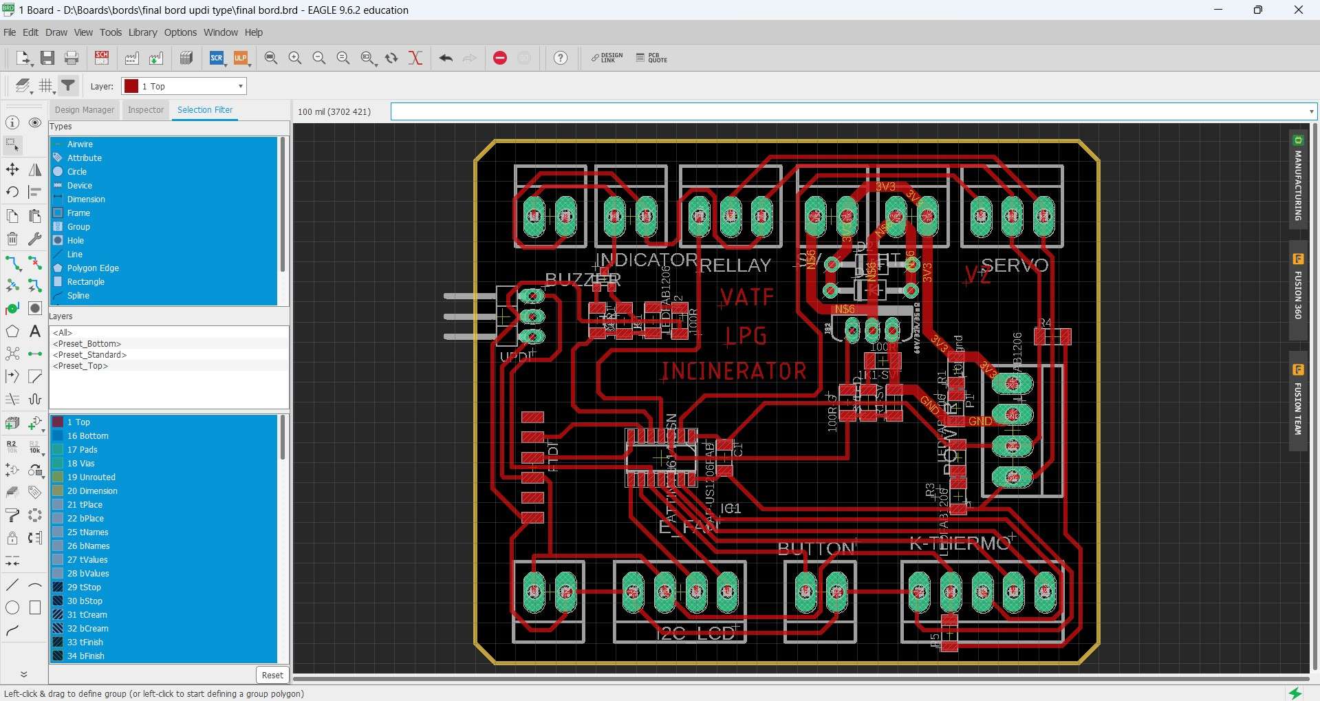
Board design.
Mill board:
Mill board.
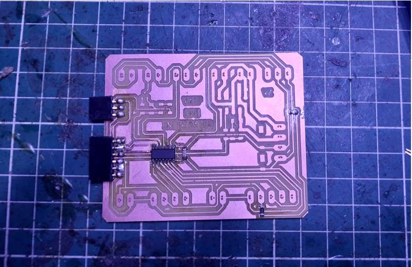
After milling board.
Soldering :
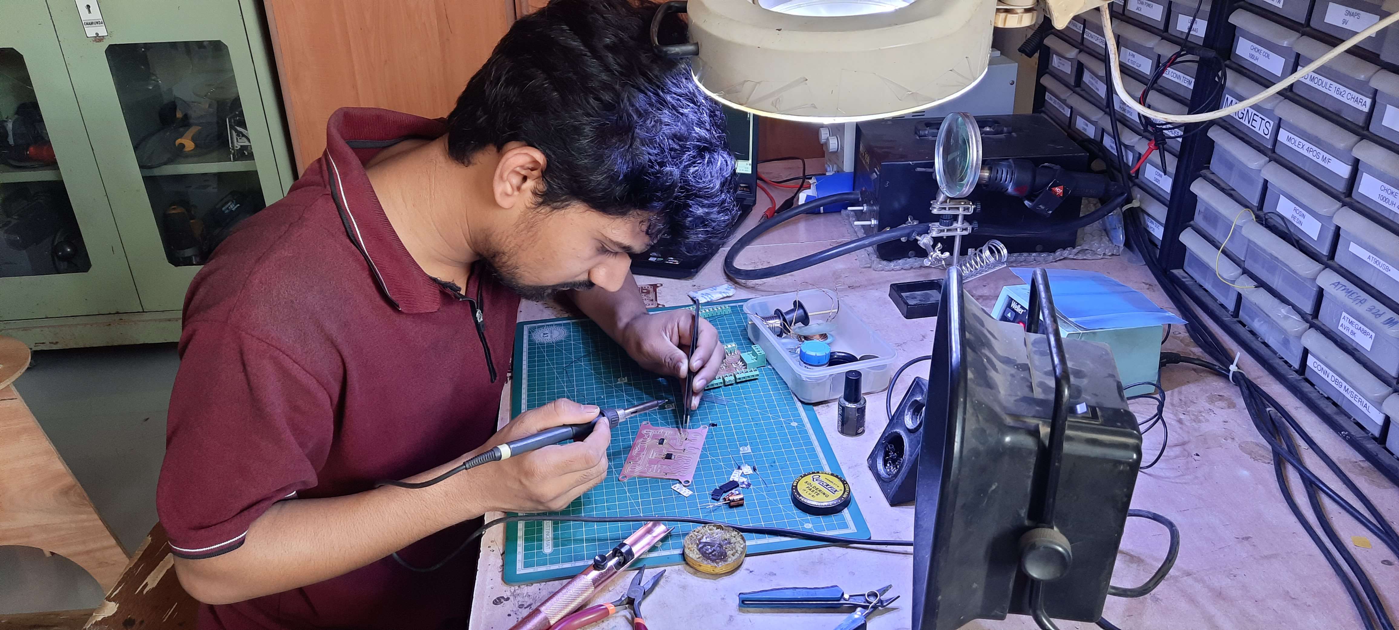
Soldering Components on board.
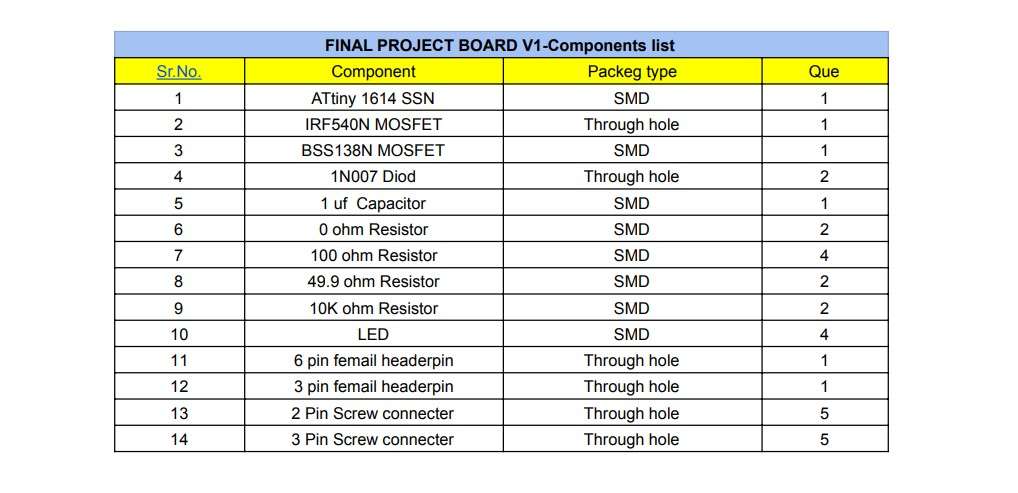
List of components in final project board.
Final Board V1:
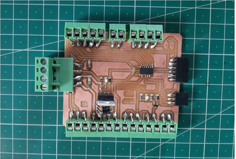
Final board V1.
Final board piout configration:
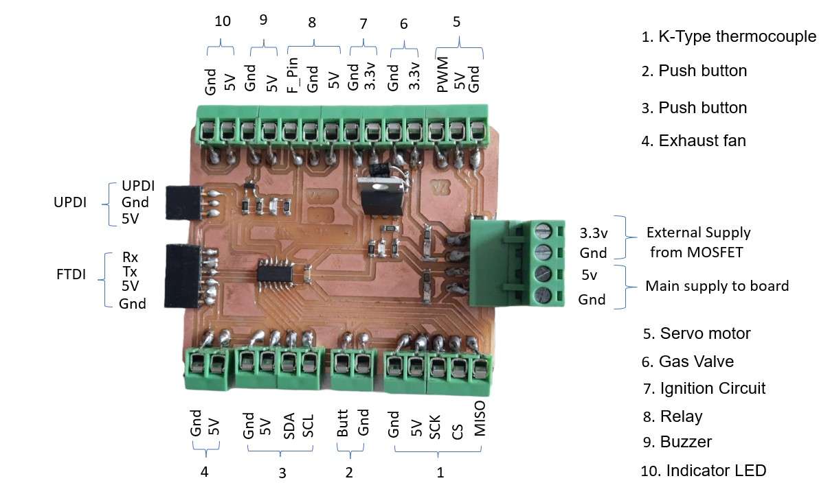
Final board piout configration.
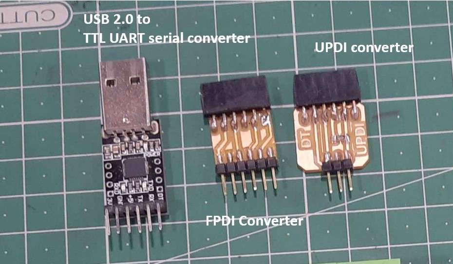
USB to Serial Converter:
FTDI Ics stock in our fab lab is empty and there is .Shortage of ICs currently going on.There four I was unable to make my FTDI programing board .Therefore I am using this CP2102(6-pin) USB 2.0 to TTL UART serial converter which I was using previously to program ESPCam module.I also design and mill this to small converter to convert Pin Output from USB to serial to UPDI and FPDI pin out respectively.I attach the schematic files below in source files.
Final board piout configration.
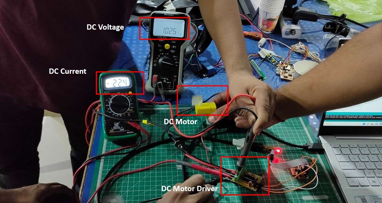
Interface Servo motor with final project board:
For this week as an output device I am trying to control some of the components in my project. servo motor is one them.I am automating the gas flow regulator in my project using the servo.
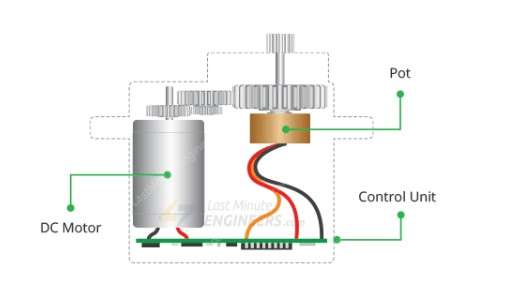
What is Servo?:
A Servo motor is a simple DC motor with a closed-loop control system .to provide accurate revolution angle during revolution.In a closed-loop system, the motor's speed and direction are changed in response to the feedback signal to produce the desired outcome.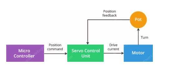
Closed-loop control system in servo motor.
It has a small DC motor that is linked to the output shaft by gearing.
The output shaft is coupled with a potentiometer and drives a servo arm (pot).
The potentiometer gives the servo control unit position feedback by comparing the motor's present position to its desired position.The control unit adjusts the motor's real position to match the intended position in response to the error.
Servo iner view.
I am using a MG995 metal gear high torque motor here.It required following connections to run.
- PWM
- Vcc
- GND
Arduino Code to run Servo:
I use this coed to interface Servo motor with final project board.
Runing Servo motor using Final project board:
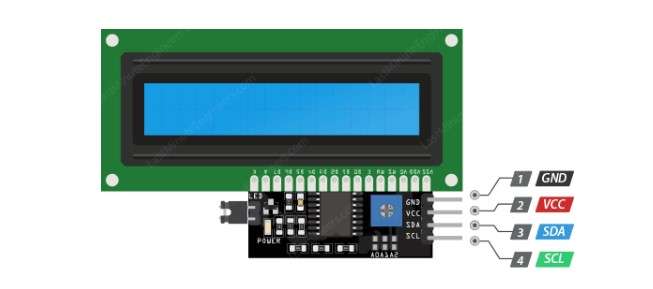
Interface an I2C LCD with final project board:
Again I am usina a 16x2 LCD (Liquid Crystal Display ) with I2C adapter as an Output device this week to Display some characters .As its name it's perfect to use to display characters .In my final project I will be using same LCD with I2C adapter to display Instructors during operating machine.
Why an I2C adapter?
I2C is the communication protocol which requires only two wires to communicate with device SDA(Serial Data line) and (SCL Serial Clock Line) an I2C Adapter is used to convert the LCD output into I2C hardware pinout.
I2C PinOut.
-
It required the following connections to run.
- SDA
- SCL
- VCC
- GND
LCD Arduino Code to Display Characters:
I use this coed to interface I2C LCD module with final project board.
Interface single channel relay module with final project board:
A Relay Is a Magnetic Switch which work on electromagnetic principle .It consist of a copper coil whig get magnetized when current is pass through it.Its a physical switch operate on attaching and detaching of metal surface.In which One of the metal strip is pull due to magnetism generated by coil to make connection known as common conection.It is generally use for switching AC power supply.I am thinking to add a AC Fan im my project .Which I think not be needed but I am making provision for it.
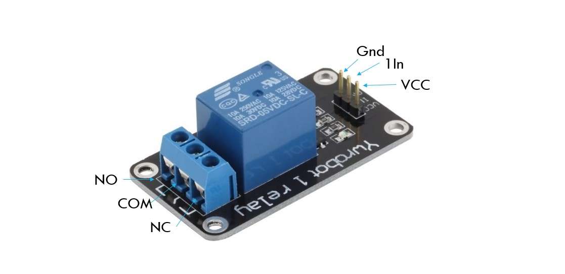
Relay PinOut.
Relay pinout:
The relay module contains 6 theminals out of which 3 are internal terminal and 3 are External terminal.Internal terminal consist of :
- Vcc
- Gnd
- 1 In (signal):it requires a digital signal pin to turn on the relay
External Terminals Consist of :
- COM (Common): This is the pin you should connect to the signal (mains electricity in our case) you are planning to switch.
- NC (Normally Closed): A normally closed configuration is used when you want to turn off the relay by default. In this configuration the relay is always closed and remains closed until you send a signal from the Arduino to the relay module to open the circuit.
- NO (Normally Open): A normally open configuration works the other way in which the relay is always open until you send a signal from the Arduino to the relay module to close the circuit.
Arduino code to operate Relay module:
I use this coed to interface single channel relay module with final project board.