The task list for this week:
- Group assignment:
- Compare the performance and development workflows for other architectures
- Document your work to the group work page and reflect on your individual page what you learned
- Individual assignments.
- Read the datasheet for your microcontroller.
- Use your programmer to program your board to do something
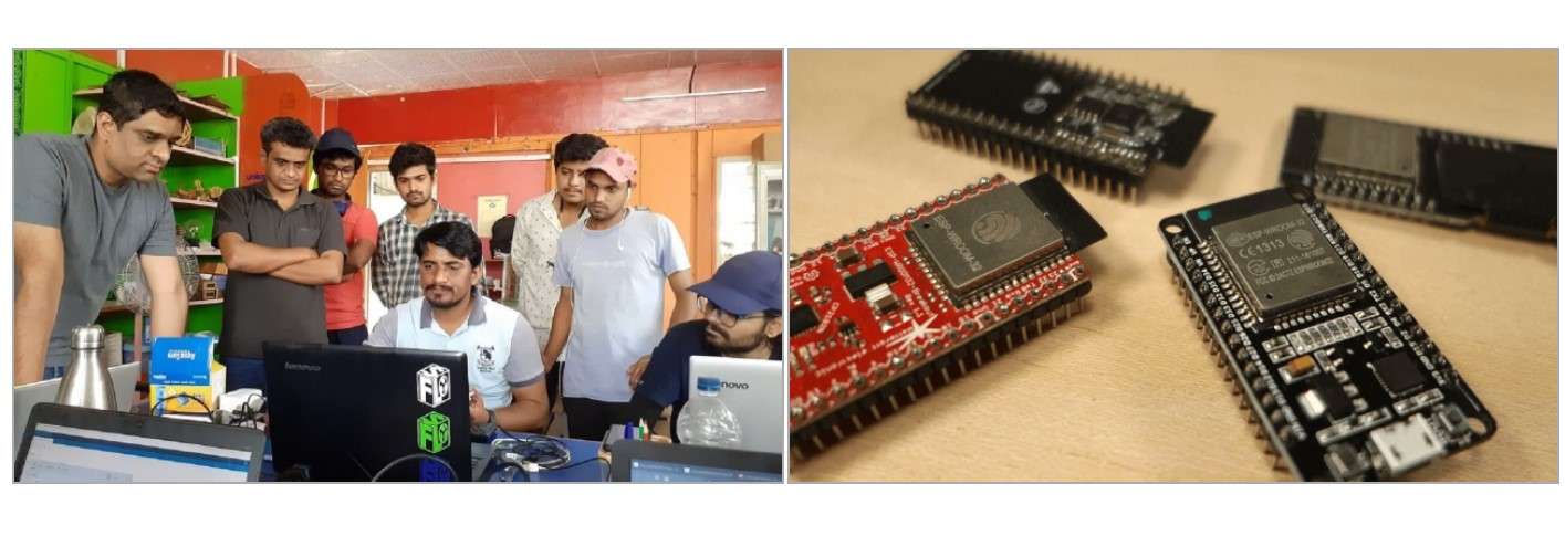
Group assignment:
In group assignment, we learn how to Code the ESP32 chip with python using VS code. We use “pymakr” extensions in VS code to upload python code on the ESP32 chip.
.
Read more About group assigment .
Individual assignments:
What is EMBEDDED System:
An embedded system is a combination of computer hardware and software designed for a specific function.
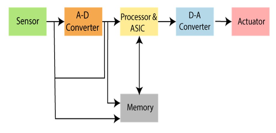
Flow of embedded system.
Embedded architecture:
There are manly two types of architecture are in Embedded as fallwo:- John von Neumann architecture:John von Neumann, a computer scientist, was the one who first suggested the Von Neumann architecture. In this architecture, both the data and instruction buses share a single data route. The CPU performs one operation at a time as a result. Either a memory command is retrieved, or read/write operations are carried out on data.
- Harvard architecture: For instructions and data, the Harvard architecture provides distinct signal and storage buses. There is no access to the instruction storage as data in this design, and all data storage is housed exclusively within the CPU. Internal data buses are used in computers to connect the distinct memory spaces for programme instructions and data, enabling simultaneous access to both types of information.
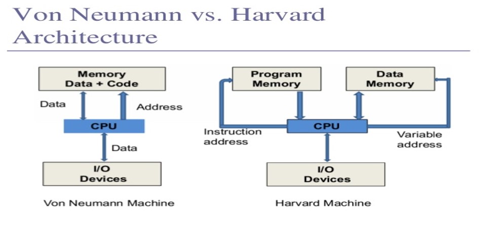
type of architecture in embedded system.
The following points distinguish the Von Neumann Architecture from the Harvard Architecture.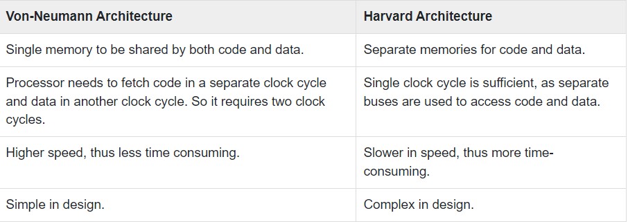
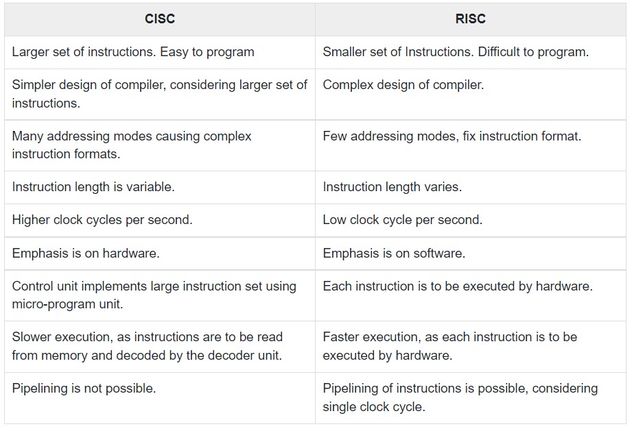
CISC and RISC:
- CISC:CISC is a Complex Instruction Set Computer. It is a computer that can address a large number of instructions.
- RISC:Reduced Instruction Set Computer Processor, or RISC, is a microprocessor design that uses a small number of highly specialised instructions. By optimising and reducing the quantity of instructions, it is designed to reduce the time required to execute instructions.
The following points differentiate a CISC from a RISC −
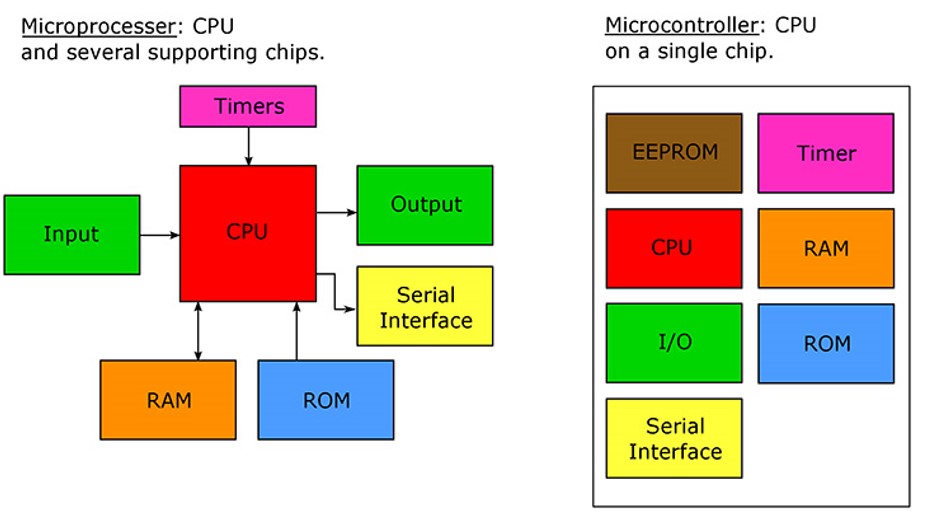
Microcontroller VS Microprocessor:
- Microcontroller :A microcontroller is a compact integrated circuit designed to govern a specific operation in an embedded system. A typical microcontroller includes a processor, memory and input/output (I/O) peripherals on a single chip. They run one specific program and are dedicated to a single task. They are low power devices with dedicated input devices and small LED or LCD display outputs.
- Microprocessor:A microprocessor is a computer processor where the data processing logic and control is included on a single integrated circuit, or a small number of integrated circuits. The microprocessor contains the arithmetic, logic, and control circuitry required to perform the functions of a computer's central processing unit. It only contains a CPU (central processing unit) but there are many other parts needed to work with the CPU to complete a process. These all other parts are connected externally.
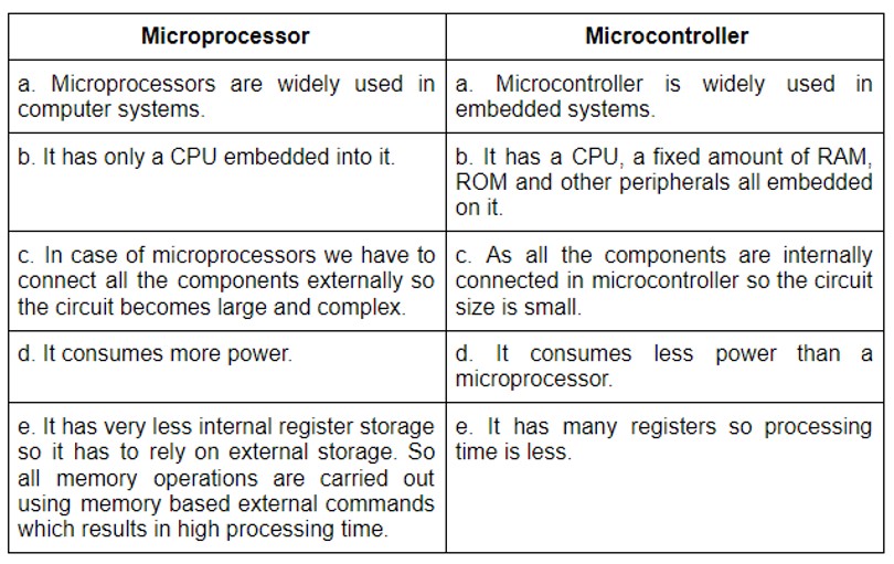
 The following points differentiate a Microcontroler and Microprocessor:
Selection of microcontroller & Read the datasheet:
This week I have to study a microcontroller datasheet. I haven't read any microcontroller datasheet though I was using them in form of dev-bords for the past few years in some of my projects where I noticed the power and pins I required for application are over of my requirement. So this time my goal was to select a proper microcontroller for the development of my final project board. I found this blog on Steps to Selecting a Microcontroller which I fallow to select my Microcontroller requirement.
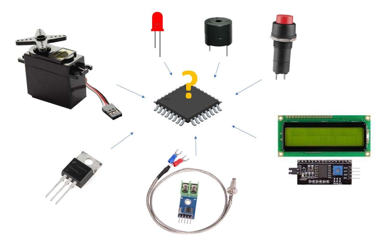
Step 1: Make a list of required hardware interfaces.
In the first week's principles and practices, I explain a little bit about my project and the preferable electronic devices I am going to use in it. Considering it I use to draw a hardware block diagram, which will give a clear image of the numbers and type of pins of microcontroller I will require for fulfilling the application. I notice two general types of interfaces that need to be listed. The first is communication interfaces such as I2C in LCD modules, SPI in k-type thermocouples and so on. These interfaces greatly affect how much program space the microcontroller will need to support. The second type of interface is digital inputs and outputs, analogue to digital inputs etc.
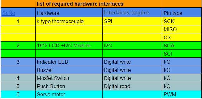
list of required hardware interfaces.
Analysing this I need 1 I2C communication interface,1SPi,4 input-output pins and 1 PWM pin in my microcontroller.
Step 2: Examine the software architecture.
The software architecture and requirements can greatly affect the selection of a microcontroller. How heavy or how light the processing requirements will determine whether you go with an 80 MHz DSP or an 8 MHz. Just like with the hardware, For example, do any of the algorithms require floating-point mathematics? Are there any high-frequency control loops or sensors? Estimate how long and how often each task will need to run. Get an order of magnitude to feel how much processing power will be needed. The amount of computing power required will be one of the biggest requirements for the architecture and frequency of the microcontroller.
Step 3: Select the architecture.
Using the information from steps 1 and 2 . I have to start getting an idea of the architecture that will be needed. There are 8,16,32 bit microcontrollers available in the fab academy. I have to just select the one.it depends on the information processing and the software algorithm written. For my requirement, I more focus on the number of pins and memory. and select the chip on the bases of it automatically selecting the suitable architecture for application with microcontroller.
Step 4: Identify Memory Needs.
Programming Flash memory and RAM are two very critical components of any microcontrollers. It is a very important point of selecting the microcontroller. the programing flash memory is the measure of program size one can flash on the microcontroller. So it is important to first identify the program size of an application. In my case, the program written for my old model is around 8 kb and additionally, I add the program for the new program I wright for K type thermocouple and LCD I2C module. which was almost 3kb. which makes 8+3=11 KB.so it's mine I need to select the controller that has a flash memory greater than 11KB.
Step 5: Start searching for microcontrollers.
On the Embedded section page. Prof. Neil introduces a lot many microcontrollers out of with I found this microcontroller available in my lab.
- ATtiny412ESP8266.
- ATtiny412.
- ATtiny1614 ,ATtiny1624 .
- ATtiny44.
- ATtiny3216 ATtiny3226.
- ATSAMD11C .
- ATSAMD21E.
- ESP8266.
- ESP32.
After reading all their data sheets in the basses on the above point.I fill ATtiny1614 or ATtiny3216 can be a better processor for my project.
ATtiny1614
It has the following specifications from the data sheet as fallow.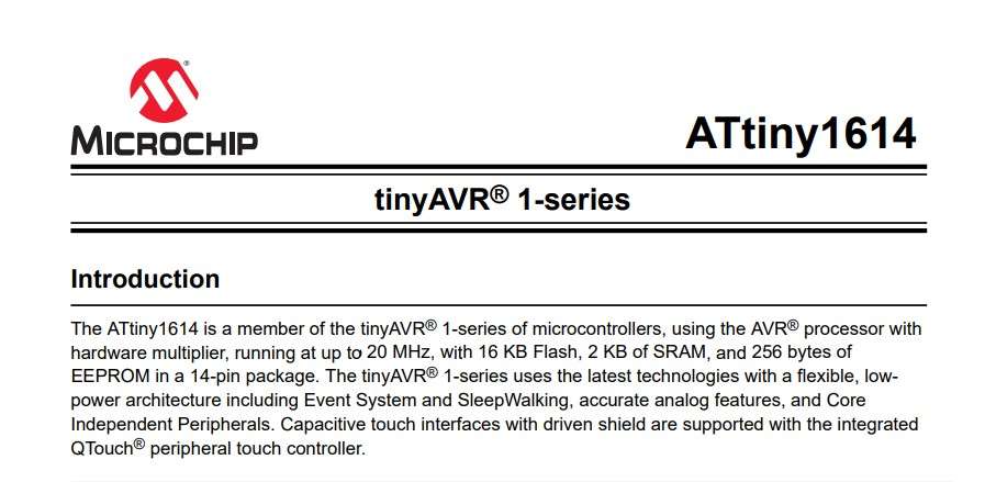
Introduction page.
ATtiny1614 Pin out.
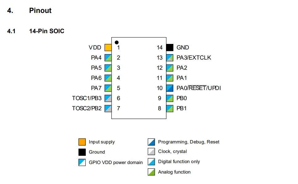
pin out digram.
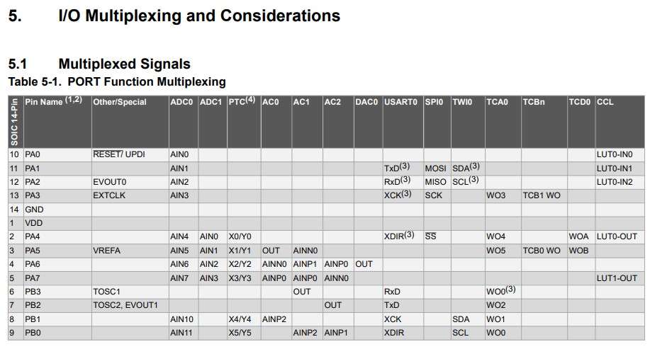
I/O pin specification.
ATtiny1614 memory specification.
>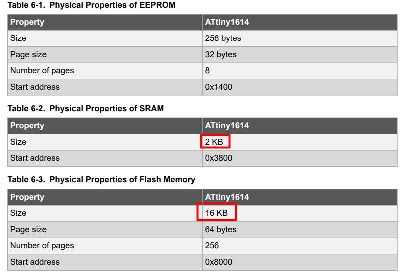
memory specification.
ATtiny1614 CPU features.
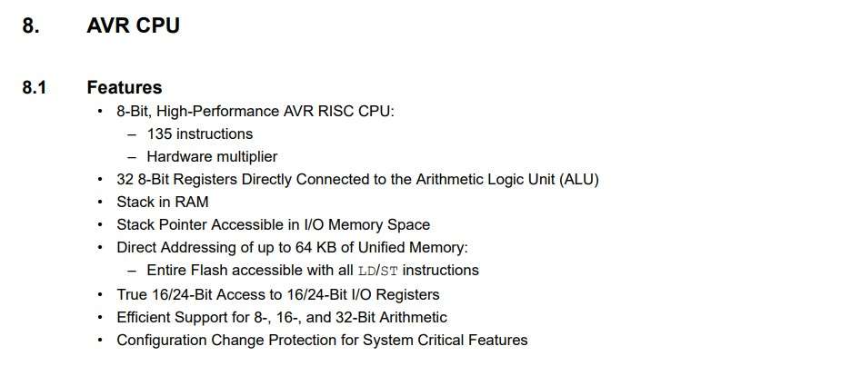
CPU features.
Conclusion of reading datasheet:
Reading above data it full file all the requirement of my application with 16KB flash memory ,14 I/O pins with I2C and SPI communication and 8 bit of AVR CPU processing.which is the requirment of my final project board to run the all components.
Programing my hello world bord:
Programming ATtiny with the Arduino IDE:
I try to program ATtiny 44 microcontroller(From the AVR microcontroller family ATtiny series ) on my hello world bord that I made during my Electronics Design week using the Arduino IDE and different programming methods.Get the Software:
For programming my Hellow world word I use Arduino IDE .it was already installed in my system.
I installed it from the official website of Arduino which you can check
here.
Programing using embedded C
What is embedded C?Embedded C is an extension of C language and it is used to develop microcontroller-based applications The extensions in the Embedded C language from normal C Programming Language are the I/O Hardware Addressing, fixed-point arithmetic operations, accessing address spaces, the language we use in Arduino IDE is embedded C.
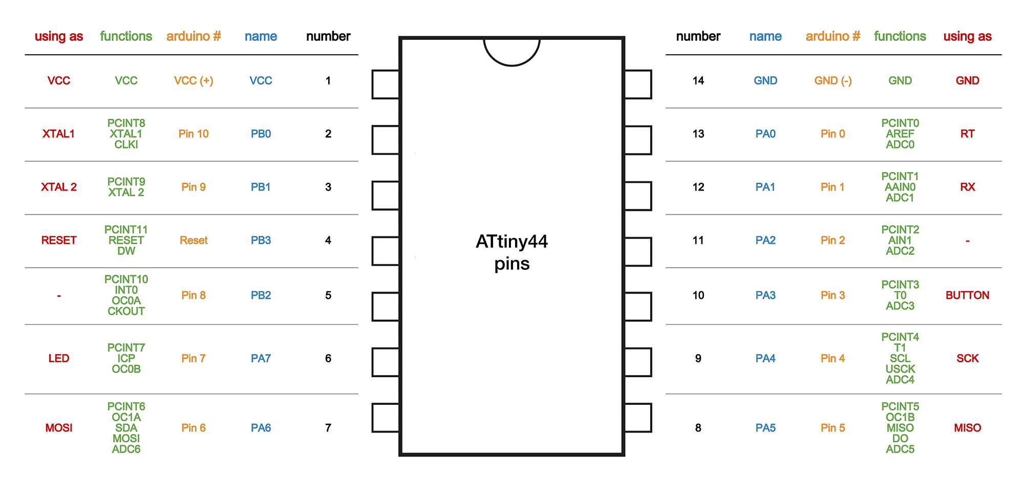
It was a little bit tricky for me to program the board with blink code which was in Arduino IDE already in the example library. In order to run the code in ATtiny44, I need to Modify the Code. The pins on ATtiny and Arduino are not the same as they are written but they are assigned as in the following diagram. In order to run the program, I need to modify the corresponding ATtiny pin with respect to the Arduino pin.
.
I wrote this code in Arduino IDE for blinking the led on my Hallo World Bord.
Code:
  /*
  Blink
Turns second LED on for one tenth of the second, then off the second one for one tenth second repeatedly.
  Written on 18 March 2022
  by Vrushabh Zunjurkar
  Fab Accademy 2022
*/
const int led1=8;

// the setup function runs once when you press reset or power the board
void setup() {
  // initialize digital pin LED_BUILTIN as an output.
  pinMode(led1, OUTPUT);
}

// the loop function runs over and over again forever
void loop() {
 // digitalWrite(led1, HIGH);   // turn the LED on (HIGH is the voltage level)
  delay(1000);                       // wait for a second
  digitalWrite(led1, LOW);    // turn the LED off by making the voltage LOW
  delay(1000);                       // wait for a second
}
Here is the Video how I upplode the blink Code to ATtiny 44 Hello bord.
Programing using pure C
Unlike in embedded C in pure C programming I have to assign the Pins on the ATtiny microcontroller by assigning the corresponding Data Direction Resistance bit address
Which can be defined using a hexadecimal or binary formate. In my case the LED is attach on PB2 pin of ATtiny44 So for that I need to define the DDR (Data direction resistance on PB2) bit value in either Binory or hexadecimal formate .In my code I have to give output on Pin PB2(for LED).To turned on it for 1000 ms (1 sec) and is then turned off again.It is important that under pure C you need to calculate the exact pin where you want to write it. In my case the LED pin 5 is on Port B2 (or in binary: 0B00000100 / hex:0x04). Same as I define in embedded C by writing Pinmode(LED,HIGH) function in Void setup() loop of arduino program.
I refer this
blog
which was very usefule.
For generating the pin value in hexadecimal or binory form our lab instructure suhas sir introduce us with a formula .which was very calcalitive part so i decided to make a calculator using the formula in excel shit as fallow.
Here is the Video how I upplode the blink Code to ATtiny 44 Hello bord.
calculater . Code:
        /*
 Blink
  Turns second LED on for one tenth of the second, then off the second one for one tenth second repeatedly.
  Written on 18 March 2022
  by Vrushabh Zunjurkar
  Fab Accademy 2022
*/

#include
#include


int main (void)
{
  // ATtiny pin no 5 (pin 5 of PORTB) for output
 DDRB |= 0x40; // PORTB5


  while(1) {
    // turn LED on
    PORTB |= 0x04; // PORTB5
    _delay_ms(500);

    // turn LED off
    PORTB &= ~ 0x04; // PORTB5
    _delay_ms(500);
  }
}
Here is the Video how I upplode the blink Code to ATtiny 44 Hello bord.
Programing using Linux Terminal (avr -gcc compiler)
For programming my bord with Linux terminal. I need a Source file that contains the C program for programming
ATtiny microchip and an A
makefile
that contains the setup terms for ATtiny44(ex bord type, programer type clock speed, etc.)
which I already found on the
lecture page .
there is already a C program that can be compiled and uploaded to the Hello Board (with an Attiny44)
just I have to modify the C source code file or it by assigning the port no. of C code for my blink program according to my connections.
I just replaced the Source code with one blinking C code I used in the last example. The page contains a readmit set making a file for ATtiny 44 and other microcontrollers too.
For uploading the code I follow the following stapes.
- Make a new folder.
- Download the source file(C source file and Make file )from the schedule page.
- Open the git bash terminal in a folder.
- Run the command make -f embedded.c.make which will compile the C code using avr -gcc compiler program and generate a Hex file .
- Run command make -f embedded.c.make program-usbtiny-fuses which will fuse the IC internal bits connections.
- Run make -f embedded.c.make program-usbtiny which will Burn the microcontroller with the program.
Using these steps and using appropriate makefile for microcontroller Now I can program any type of microcontroller directly on linux.
For more Information, I refer to this tutorial which was helpful.
Tutorial 1.
Tutorial 2.