The task list for this week:
- Group assignment:
- probe an input device's analog levels and digital signals
- Individual assignments.
- measure something: add a sensor to a microcontroller board that you have designed and read it.
- PINOUT:
- VCC: 3.3V-5V power input pin
- GND: 0V power pin
- OUT: Digital Output Pin
- TECHNICAL SPECIFICATION/RATING
- Operating Voltage: 3.0V – 6.0V
- Current: at 3.3V : ~23 mA & at 5.0V: ~43 mA
- rxPin: the pin on which to receive serial data.
- txPin: the pin on which to transmit serial data.
- inverse_logic: used to invert the sense of incoming bits (the default is normal logic). If set, SoftwareSerial treats a LOW (0v on the pin, normally) on the RX pin as a 1-bit (the idle state) and a HIGH (5V on the pin, normally) as a 0-bit. It also affects the way that it writes to the TX pin. Default value is false.
- Syntax:analogRead(pin)
- int sensorValue = analogRead(A0);
- Serial.begin (9600);
Group assignment
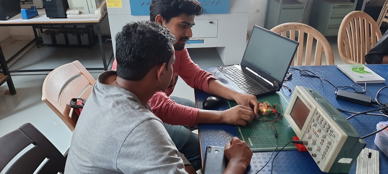
Study Input devices .
This assignment was about studying various kinds of input devices and studying their input signals.
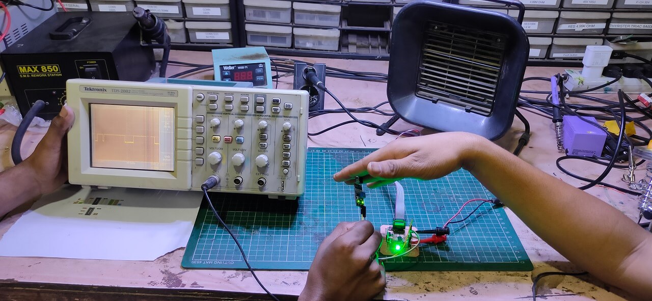
Study digital waves form of signal using IR .
To study the digital Input signals use IR Sensor as a digital input device and use digital read function to programit with my I/O board.We use digital oscilloscope to study digital waves form of signal.
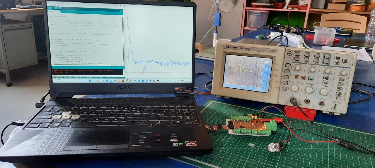
Study Analog waves form of signal using potentometer.
Similarly to study the Analog Input signals we use potentometer as an analog Sensor and use Analogread function to programit with my final board.We use digital oscilloscope to study Analog waves form of signal of the input.
Check here to read more about our group assigment.Individual assignments:
Sensor:
A sensor is a device that detects and responds to some type of input from the physical environment.
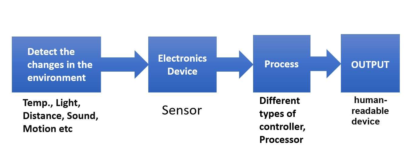
How a sensour work.
Sensor I am using:
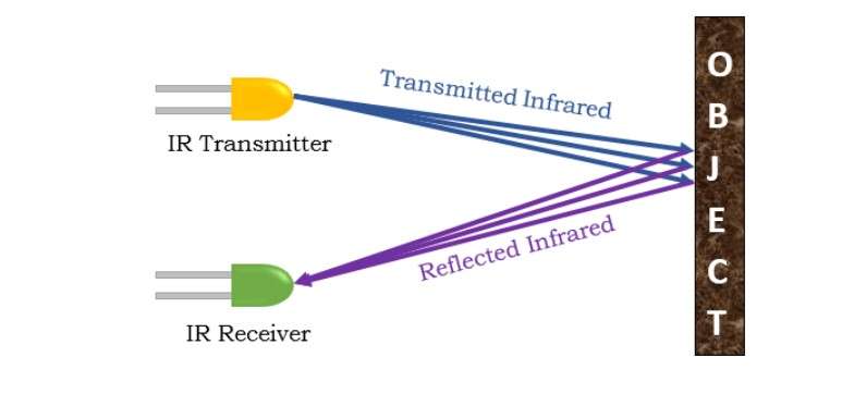
IR Sensor:
An infrared sensor is an electronic module which is used to sense certain physical appearance of its surroundings by either emitting and/or detecting infrared radiation.
IR sensors are also capable of determining the heat being emitted by an object and detecting motion.

.
Working of IR sensour:
An IR sensor is use to detecting obstacles. IR transmitter transmits IR signal, as that signal detects any obstacle in its path, the transmitted IR signal reflects back from the obstacle and received by the receiver.
.
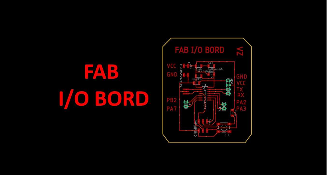
Making a I/O board:
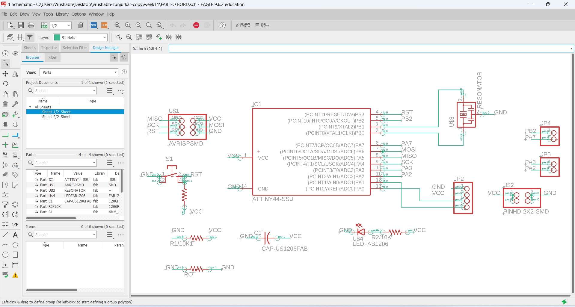
For our individual assignment this week I deside to make a Input board base on ATtiny44 .Using EAGLE .
Creating Scametic Digram:
.
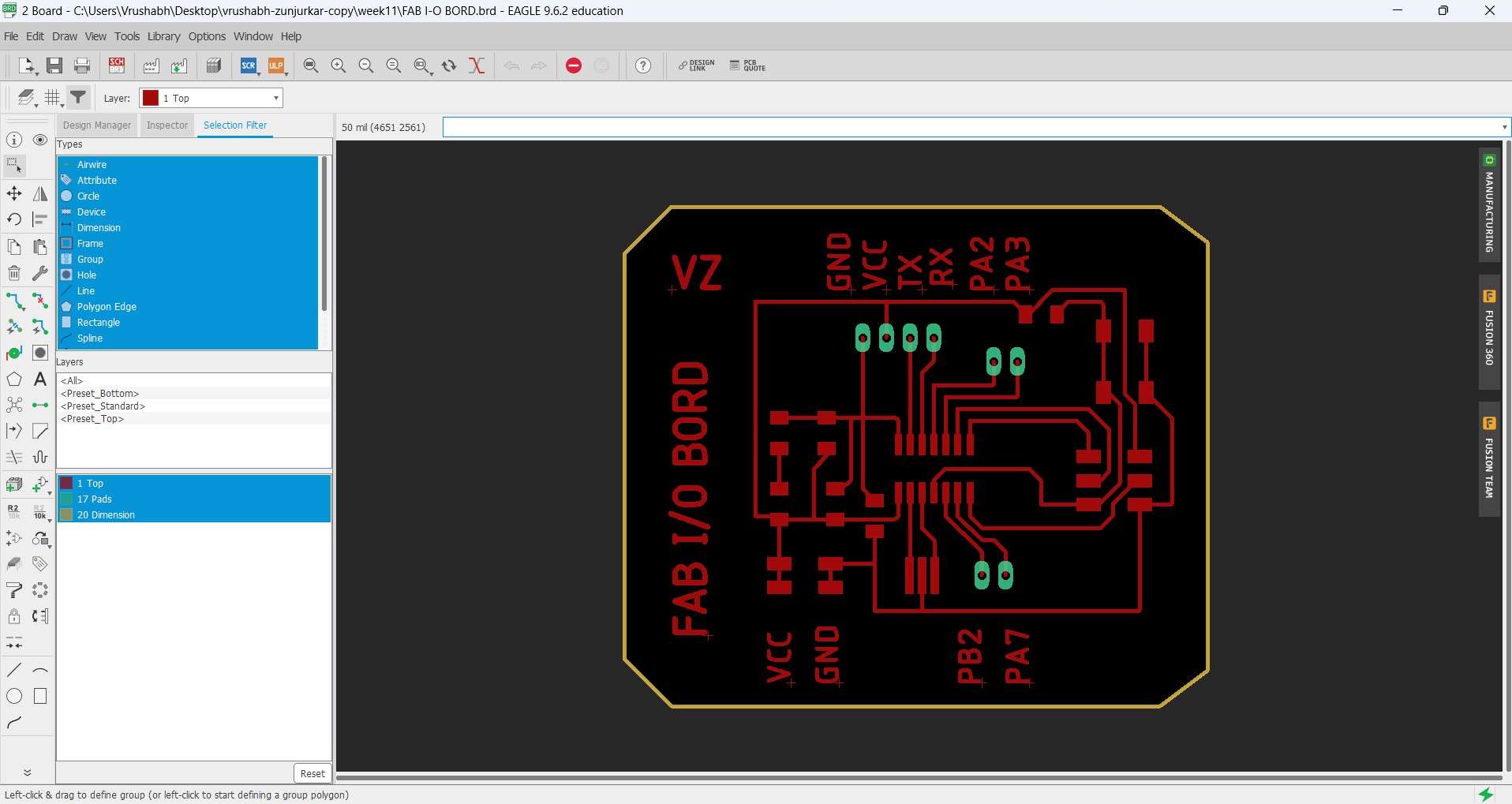
Creating PCB layout:
.
PCB milling:
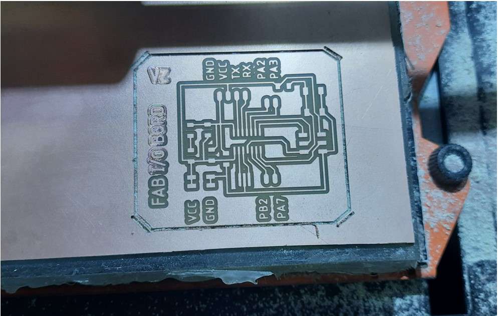
.
Soldering I/O board
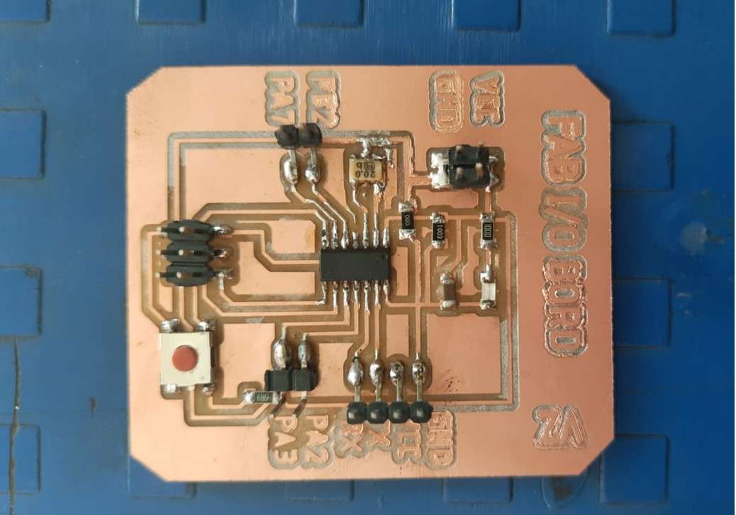
.
Components requird.
.
Programing I/O board.
Seting up Arduino IDE for Programing I/O board (Attiny 44).
SoftwareSerial Library
ATtiny 44 Does not have Rx and Tx pins define in it .So For reading the Signals through FTDI we required them.So I have to define theme externally via softwere.For that I am using a SoftwareSerial library which allows serial communication on other digital pins of an Microcontroler board .
SyntaxSoftwareSerial(rxPin, txPin, inverse_logic)
Parameters
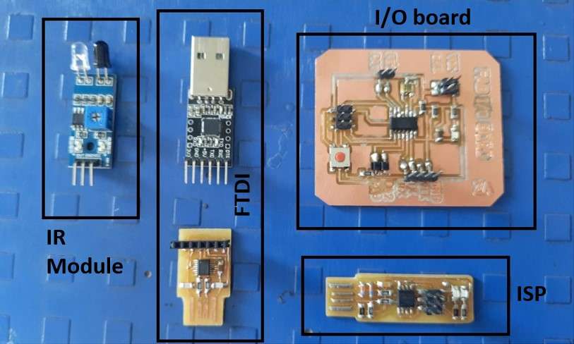
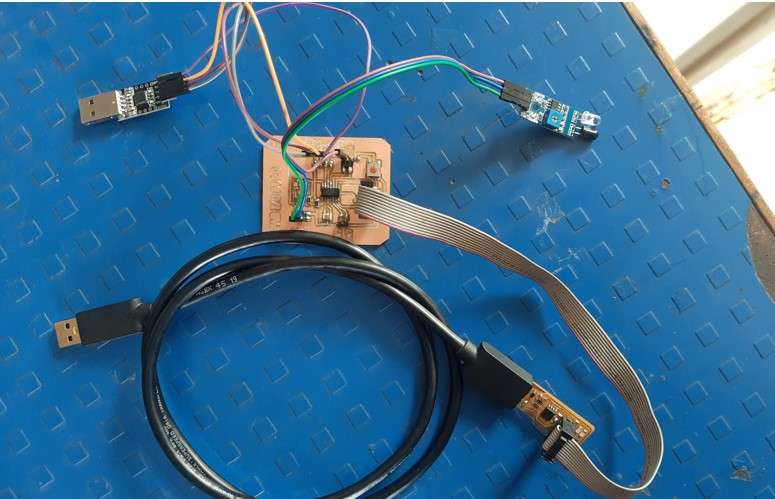
Setting hardwere.
To Study Input Signals through FTDI .I need to install SoftwareSerial Library .As I told because of the limited supply od FTDI ICs .I couldnt make my own one .But I am using this boutout CP2102(6-pin) USB 2.0 to TTL UART serial converter .As an FTDI to read the signals using Arduino Serial monitor.
Data reading functions in programing :
analogRead()
Read the value of the specified analog pin.
sensorValue
analogRead() returns a number between 0 and 1023 that is proportional to the amount of voltage being applied to the pin.
Serial.begin(9600)
This starts serial communication, so that the Arduino can send out commands through the USB connection. The value 9600 is called the 'baud rate' of the connection. This is how fast the data is to be sent.
Reading IR sensour module input signial using I/O board.
AnalogRead Serial code.
AnalogRead Serial code.
Serial Monitor output on Arduino IDE.
Serial Plotter output on Arduino IDE .
K-Type Thermocouple with MAX6675 Amplifier as an Input devise.
What is Thermocouple?
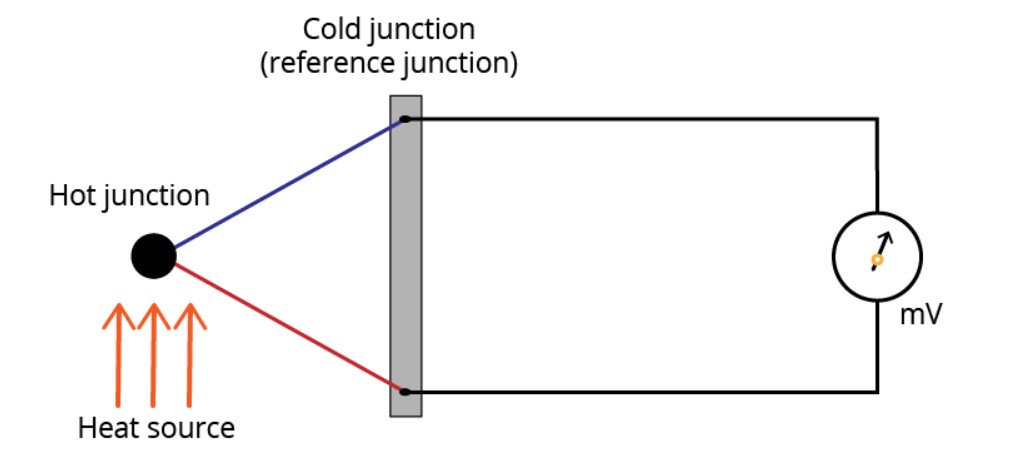
A thermocouple is a device that consists of two different metal that form an electrical junction—thermal junction. The change in temperature at junction creates a small measurable voltage at the reference junction that can be used to calculate the temperature.This is also known as Seebeck effect.
A thermocouple is classified on base of different metals junction they use . The metals used will affect the voltage range, cost, and sensitivity. There are standardized metal combinations that result in different thermocouple types: B, E, J, N, K, R, T, and S.
A k-type thermocouple is made out of chrome and alumel conductors junction and has a general temperature range of -200 to 1260ºC (-326 to 2300ºF).
MAX6675 Amplifier
The MAX6675 Amplifier performs cold-junction compensation( sensor to measure temperature at the reference junction) and digitizes the signal from a type-K thermocouple.Amplifies the tiny voltage at the reference junction so that we can read it using our microcontrollers. The data is output in a 12-bit resolution, SPI-compatible protocal , read-only format.So it can be readable by a microcontrol.
For more information read the datasheet.
Code for K-type thermocouple with MAX6675 Amplifier.
Code for temperature reading.
Themprature reading from K-type thermocouple .
Tempratur reading in degree celcius.
In this week I want to test K-type thermo couple .which will be used by me in my final project to. As my project is based on Heating Application .I have to give Some kind of Security Alert for high temperature.Why K-type thermo couple ?
My project is base on LPG incineration so.The body will enclose the fire with temperature goes above 700-800 degree celsius.Becous A K-type thermocouple is a type of temperature sensor with a wide measurement range like - 200ºC to 1350ºC (-326 to 2300ºF) .Its the perfect sensor for my application.
Using Push button as an input device.
I try to use a push button as an Input device to start the program in my final project board .Currently I want to operate it as a one push ON/OFF button to turn ON/OFF a button.
One push on/off Code:
One push on/off video demonstration: