.jpg)
The task list for this week:
- Group assignment:
- Test the design rules for your 3D printer(s).
- Document your work and explain what are the limits of your printer(s) (in a group or individually)
- Document your work to the group work page and reflect on your individual page what you learned
- Individual assignments.
- Design and 3D print an object (small, few cm3, limited by printer time) that could not be easily made subtractively.
- 3D scan an object, try to prepare it for printing (and optionally print it)
Group assignment:
So we have done multiple precision tests on our Fracktal works CNC 3D printer to formulate Design rules for our assignment. Click here to know more about our teamwork.
Group assigment link.
Precision Test:
For this week every individual member in the team holds to study at least one design rule. For my study, I got a free overhang design to work on.
Here is some work done by me in the assignment.
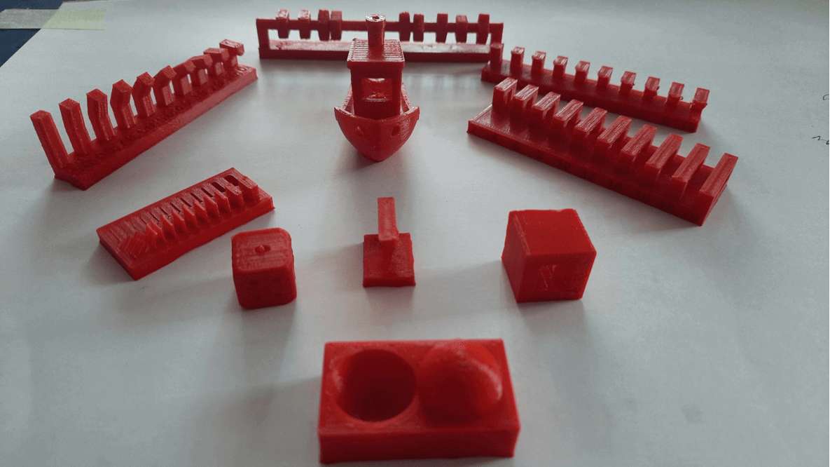
objects print for 3D printer pricigen test.
Free Overhang test(unsupported): I download the pre-prepared file From this week assignment's schedule page and print it on Fracktal works CNC 3D printer in our lab.
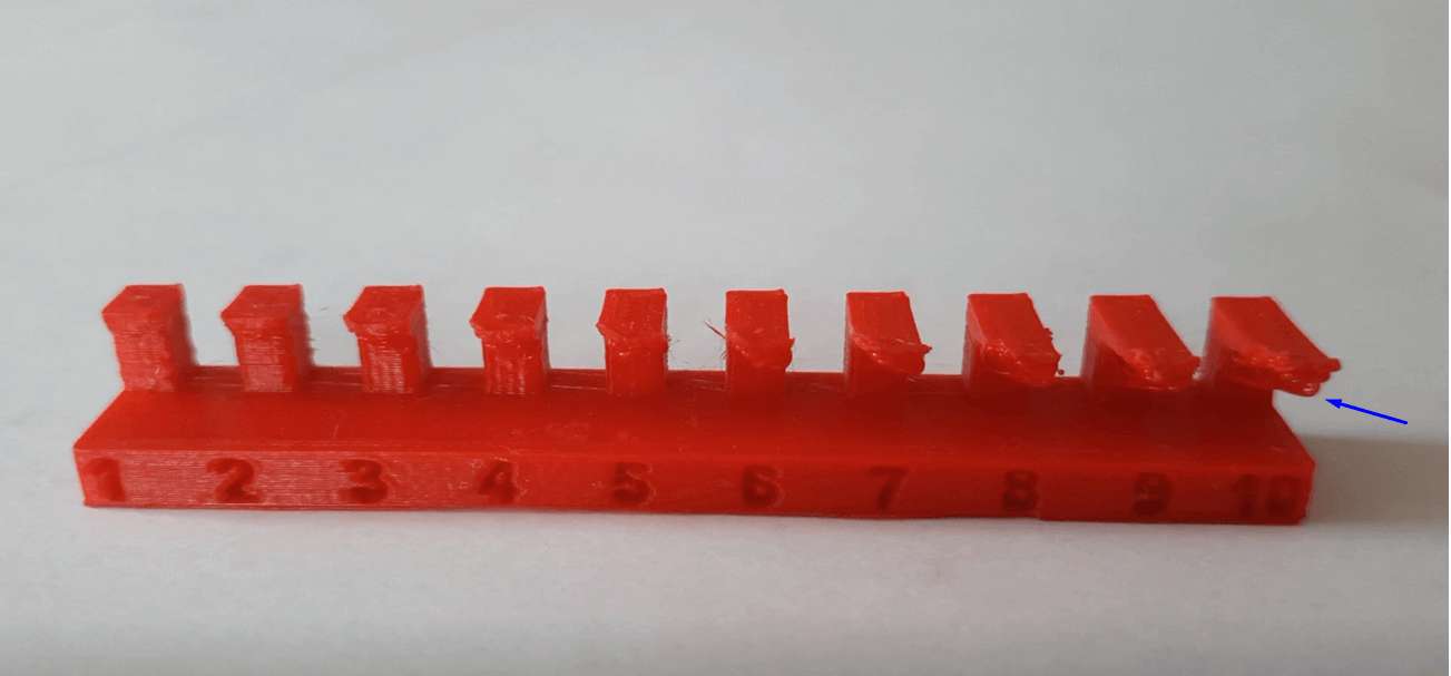
free Over hang .
Results: As you can see in the image, After 3D printing the Overhangs file, all the 6 out of 10 overhangs in the design failed and had some flaws resulting in improper 3D printing. The top layer is not printed fully. The printing is tapered from the centre to the outer edge. Also, the lumps are hanging at the bottom of every overhang. The overhang up to 4mm and below are passed but the overhang above 4mm failed.
Conclusion: From the above result, It could be concluded that with the above-mentioned parameters of 3D printing on fractal works Julia Extended machine all the overhangs above 4 mm length with angles zero-0 need a support structure to print.
This whole printing is done with PLA(Polylactic acid) material.
Individual assignments:
Types of Manufacturing Process:
Subtractive Manufacturing :Subtractive manufacturing, such as milling and turning, creates objects by removing (machining) material from a block of solid material.
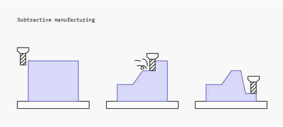 •Subtractive manufacturing is best for medium volumes, simple geometries, tight tolerances, and hard materials.
Formative Manufacturing : Formative manufacturing, such as injection molding and stamping, creates objects by forming or molding materials into shape with heat and/or pressure.
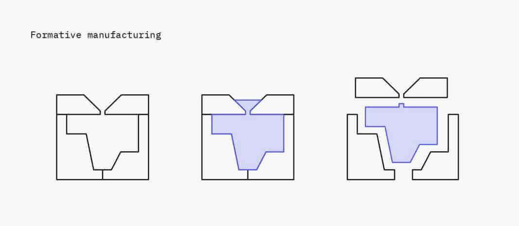 Formative manufacturing is best for the high-volume production of identical parts.
Additive Manufacturing :Additive manufacturing builds up 3D objects by depositing and fusing 2D layers of material.
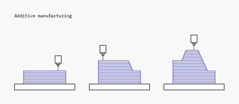 Additive manufacturing is best for low volumes, complex designs, and when speed is essential.
CNC 3D Printer:
3D printing or additive manufacturing is a process of making three dimensional solid objects from a digital file.
Where we use a CAD (computer-aided design ) file as a digital form of information to operate a CNC machine with an end tool as an extruder excluding material to layer by layer disposition of material controlled by my machine to form an object.
Chuck Hull is typically credited with the invention of the 3D printer via his Stereolithography Apparatus (SLA), patented in 1984.
‘Rapid prototyping’ refers to 3D printing, the phrase is evolving to refer to all forms of very fast prototyping.
3D printing Processes.
- Vat Polymerization: liquid photopolymer is cured by light.
- Material Extrusion: molten thermoplastic is deposited through a heated nozzle.
- Powder Bed Fusion: powder particles are fused by a high-energy source.
- Material Jetting: droplets of liquid photosensitive fusing agent are deposited on a powder bed and cured by light.
- Binder Jetting: droplets of liquid binding agent are deposited on a bed of granulated materials, which are later sintered together.
- Direct Energy Deposition: molten metal simultaneously deposited and fused.
- Sheet Lamination: individual sheets of material are cut to shape and laminated together.
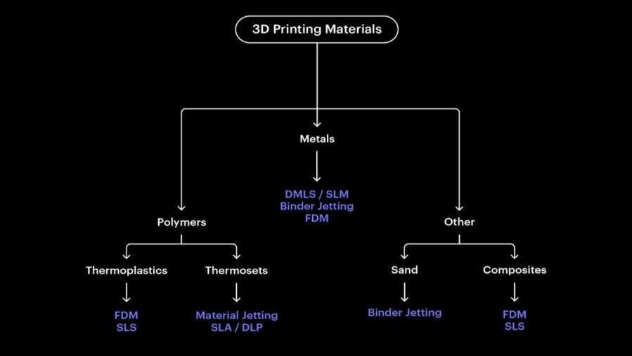
Tree digram explaning 3D printing processes.
In my case, I am mainly focusing on Fused deposition /Material extrusion type one.
Fused deposition/Material extrusion:
Material extrusion technologies squeeze a material through a nozzle and onto a build plate, layer by layer to print one cross-section of an object (in the X-Y or horizontal plane), then moving up vertically (Z-axis) to repeat the process for a new layer, thus prints from the bottom upwards. The printer nozzle contains resistive heaters that melt the plastic as it flows through the tip and forms the layers. The extruded plastic then hardens immediately as it bonds to the layer below it.
Fused deposition modeling (FDM) falls under the most widely used 3D printing technology. Fused deposition modeling Benefits
Some characteristics of FDM 3d printing
- Benefits Fast , Low cost ,Common thermoplastics.
- Limitations Rough surface finish,Anisotropic ,Usually requires supports,Not scalable,Limited accuracy.
- Quality Factors: Layer height, material quality, bed level, temp., orientation, nozzle speed, feed rate.
- Resolution: Range of 75 to 300 microns.
- Temperature: Range of 170 and 240 degrees Celsius, depending on the type of material being used.
- Material: Thermoplastics or thermoplastic/organic-material blends. ABS, PLA, polycarbonate (PC), PVA, ninja flex.
3D printer in our lab :
At vigyan ashram we have a fracktal works Julia Classic model 3D printer .which is an cartesian type Fused deposition modeling (FDM) 3D Printer.
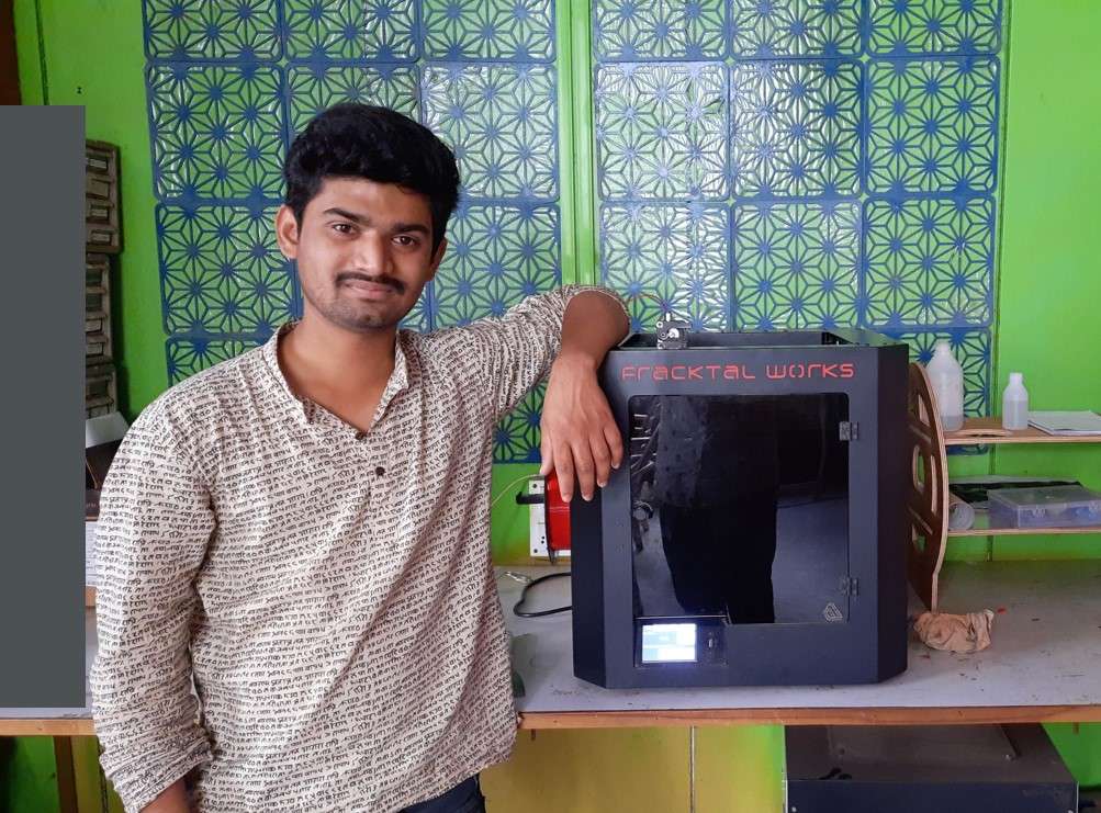
Vigyan ashram fab lab CNC 3D printer machin.
Vigyan ashram fab lab CNC 3D printer machin.
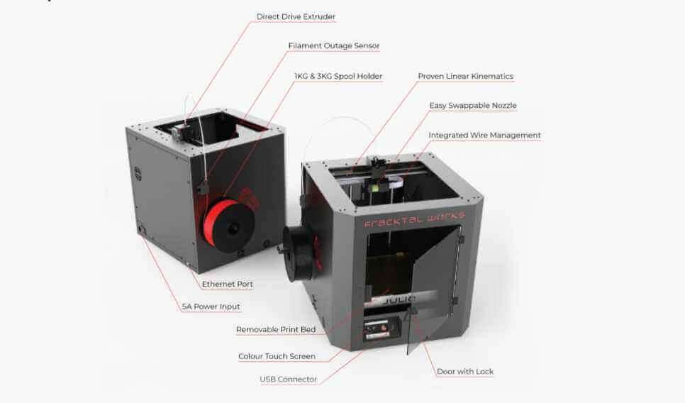
Its Specifaction are as following.
- Bed Size:250 mm x 250 mm x 300 mm
- Print Technology: Fused Deposition Modelling (FDM)
- Filament Diameter: 1.75mm
- Nozzle Diameter: 0.4mm
- Nozzle Temperatures:Upto 240 °C
- Bed Temperature: Upto 110 °C
- Compatible Materials:ABS, PLA, Tough PLA, PLA+, PETg, PVA, PVA+,BVOH,Polycarbonate
- Nylon 12*, Carbon Fiber Nylon*, Carbon Fiber PLA.
- Supported File Types: STL, OBJ
- File Transfer :USB Pen Drive, WIFI, LAN
.
CNC 3D Slicing softwere:
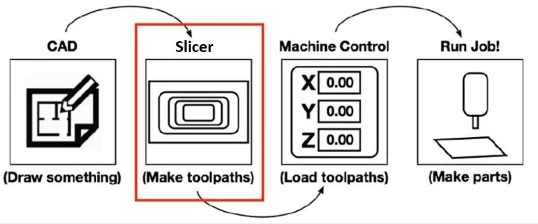
A slicer is like a CAM software that converts the digital 3D model's CAD model into machine-readable code (usually G-Code) for a 3D printer to build an object .most of the 3D printer required STL files formate to generate machine code.In addition to the model itself, the instructions contain user-entered 3D printing parameters, such as layer height, speed, and support.
I use Fracktal Works slicing softwere for creating G-code file for 3D printer.This is based on Cura. Cura is an open-source slicing application for 3D printers.
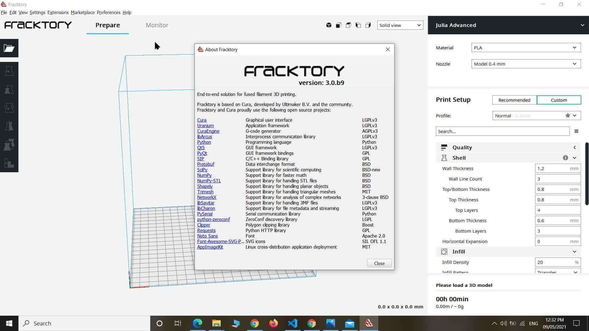
Fracktal works slicing softwere.
My Individual Designe:
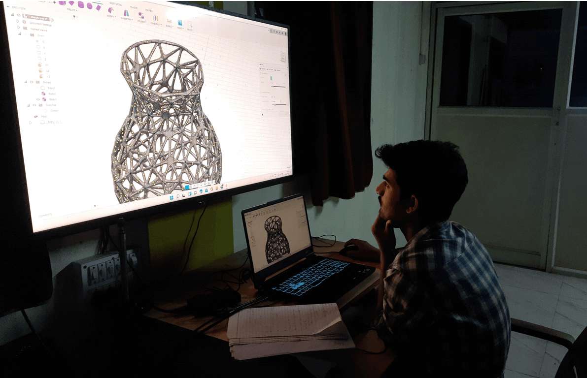
my individual design.
For this week of 3D printing, I decided to make an Organic design. As we were told to make something that we can not make using the machining process(Subbractive manufacturing ). So I search for a couple of organic design tutorials on Youtube and google some 3D design sources. I stick to the one tutorial where he creat the Organic design using Fusion 360. this was challenging to make as the steps he mentioned were not exactly the same as applicable for my design. So I tried to understand the concept and try It in my way as follows.
Design Steps:
Step 1: I sketch a pot shape and use rotate command to make a pot shape body.
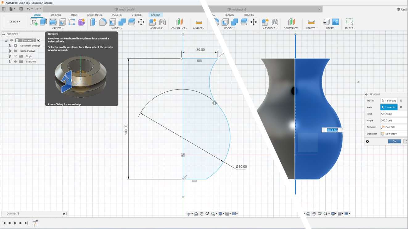
Creat Pot body.
Step2: Then I save the Body In mash(STL binary ) form as you can see in the image below.
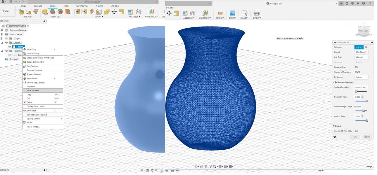
Saving in STL(Mash) format.
Step3: After importing the mesh body in the new window of Fusion 360. I go to MESH>MODFY>Reduce and use reduce command to minimise the no. of matches on the body.
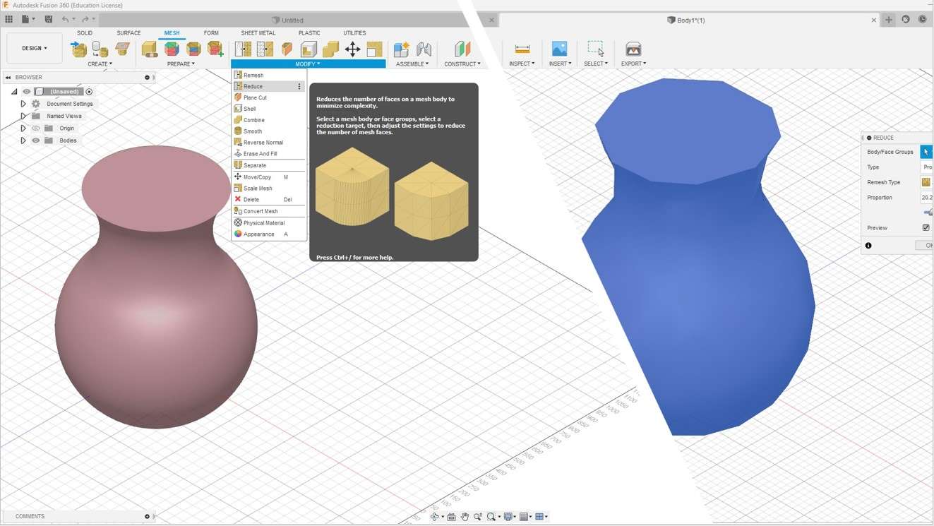
Reduce no. of mesh using Reduce mesh command.
Values that I Modify
- Ramesh type: Adaptive
- Proportion:20.283
Step 4: After reaching the mesh body I convert it into a Normal Body using the Convert Mesh command in Fusion 360. for that go to
MESH >MODFY>Convert mesh
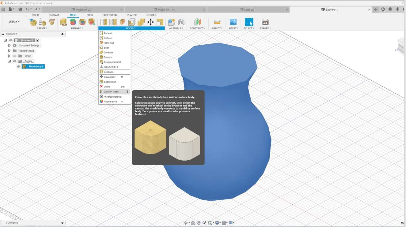
Convert mesh.
Step 5: Now here is the trick for creating the organic effect I use mesh edges as a path as you can see. For selecting the mesh edges I set select on select through and body edge only and drag on bogy to select mesh edges and unselect the unnecessary edges portion I need not in design.
Solid >SELECT>Selection Fiters>Select throught>Body Edges.
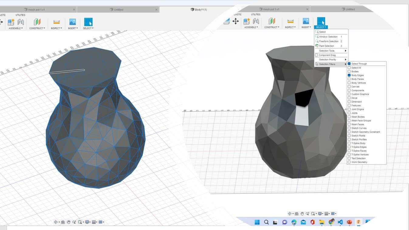
Selecting mesh edges.
Step6: Now to make the organic structure I go to Forming section and select the pipe command making sure the edges are selected.
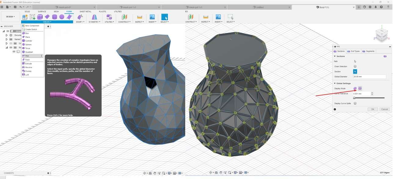
my individual design.
Values that I Modify
- End Type: Square.
- Section: Global dimeter:2.00mm
- Curve Tolerance 1.55
pleas for your design set this parameter. As you fill suitable one for it.
Step7: Final step I use the Boundry fill command in Fusion 360. To fill pipe cavity. For that, I go to
SOLID>CREAT>Boundry fill.
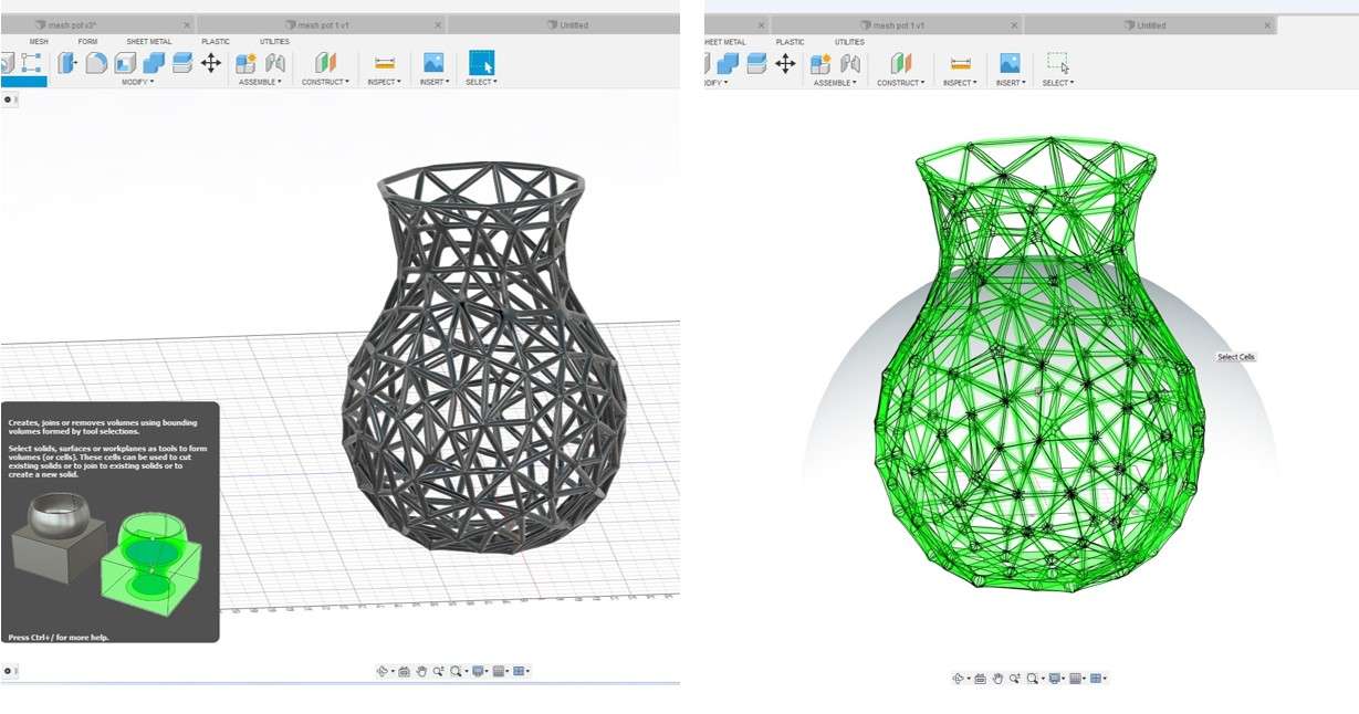
Boundry fill command .
Looking through the section view: You can see the difference between the before boundary fill command and after the boundary fill command. It makes the pipe structure solid.
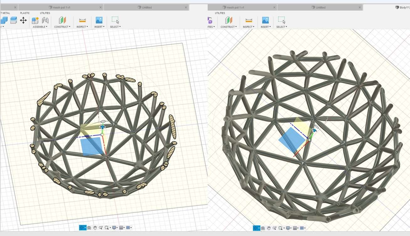
cross section view.
Step 8:Now the final step is to save the New organic body in form of an STL file for 3D printing. for that, I hight all unnecessary bodies in the design tree and select the organic structure body left click on it and save it as binary STL as done in STEP 2.
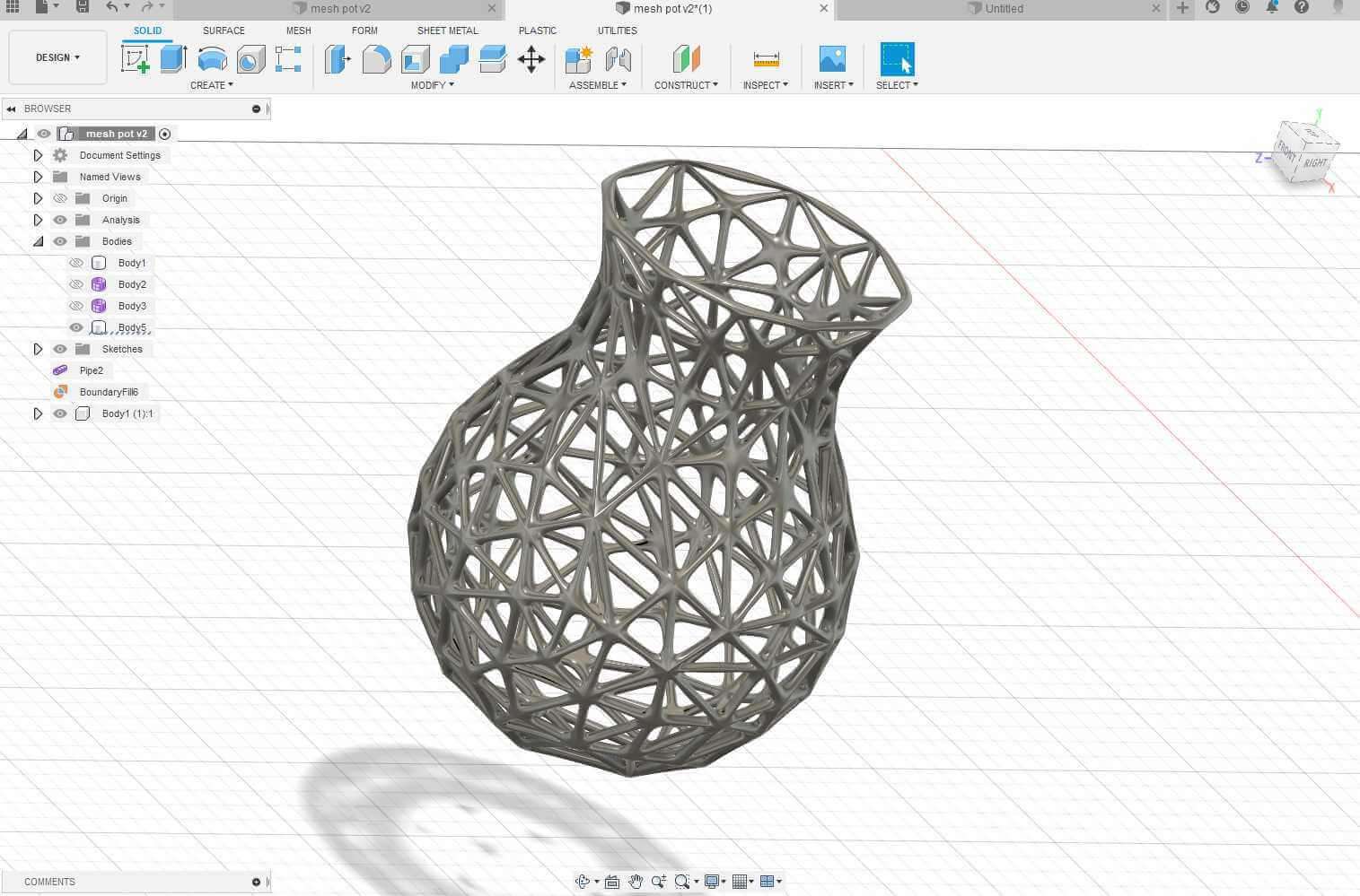
Mesh pot.
This is the 3D view of my design as you can see in skechfa platform.
Why 3d mesh-pot printed can be made only with additive manufacturing?
As I mention it is an organic design. Its thin mesh net pipeline structure which I make using generating the arbitrary mesh vectors makes it impossible to make such a fine arbitrary pipeline structure by using any subtractive manufacturing method. So this design can be only fabricated using the additive manufacturing process such as a 3D printer as per my knowledge.
Generating G-Code:
As I mentioned earlier I am using a factory works 3D printer so I am using there Software to generate the G code for The STL file I make. It's easy to handle it.
Print 1:Scale down the design
After designing I came to know that the design I made was big in size and it would take considerable time to print. So I decided to make it small. For that, I use the scale down feature in factory work to make it 50% smaller than what it was, which is around a cube of 50 mm^3.
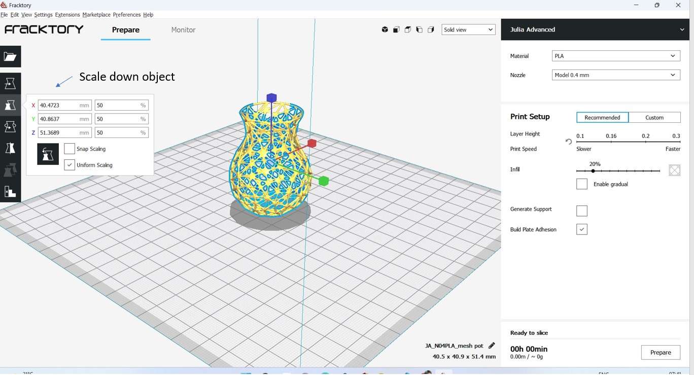
useing Scale feature to make print smaller .
In the following image, I try to show some of the features of the factory works slicing software. I use the move and rotate command to move the object at one corner of the 3D printer bed as our bed is not in a condition to print images at the centre position.
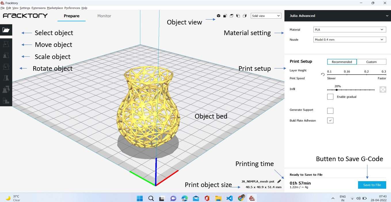
generating G-code .
Values that I Modify
- Material: PLA
- Nozzle diameter: 0.4mm
- Bed temp: 60
- Nozzle temp: 210
I use PLA material as a starter for my 3D printer learning. I also hear it is an entry-level best material for learners. Also, I hear it is some kind of sticky material and It will be best for thin layer printing purposes.
In my first trial of 3D printing as you can see I failed to print the complete object. The region had less surface contact with the bed. Due to this, the object gets dislocated from the bed in the middle of printing and I end with a half printed part.
1st time printing design failed .
Print 2:Invert the design.
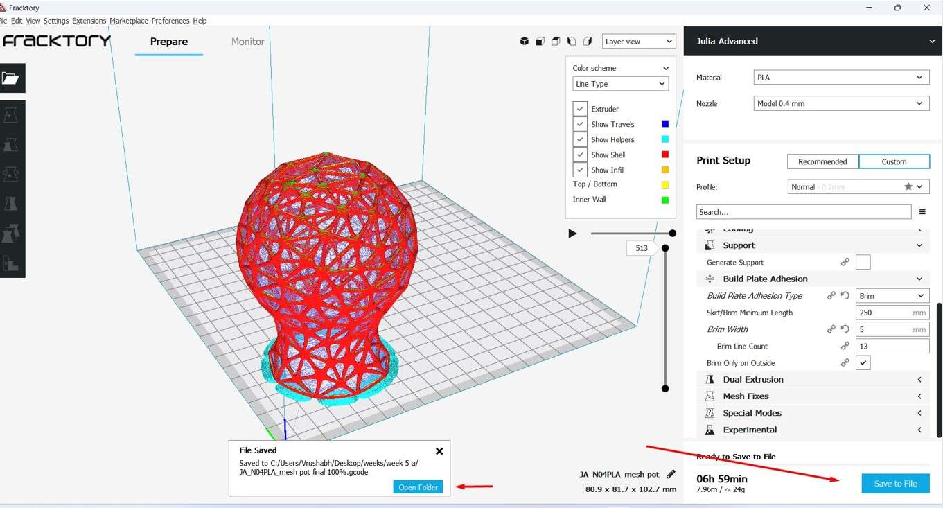
In the second print I try to print the pot from the upper to lower side and provide a Brim of 5mm which acts as a Build Plate Adhesion to prevent the object from dislocating hoping it will work. This Idea was suggested by my local instructor at our regional review.
For providing Bimp I go to:
Printer setup>Custom>Build plate Adhesion>Build plate Adhesion type>Brim.

Image showing how I generate Brim to support the pot .
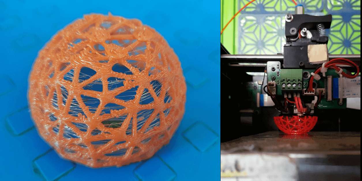
This time the Print started printing nicely but again due to the thin wired structure the print was too dedicated. The printer stops printing automatically in middle of print . Later I realized that was not my issue anymore but it was the 3D printer firmware issue which was solved with the help of a service engineer later.
2nd time design failed .
As you can see due to the thin pipeline structure there some threaded spider net structure was created while printing. The Brim I generated was perfectly printed. This was my observation .and I was now thinking to make the diameter of the mesh pipe structure bigger to print it nicely or either give some support structure other than Brim over the mesh pot to make it nicely printed.
nicely printed Brim and some spidy net structure observation.
Print 3:Generating the support.
After the last trial, almost 2 weeks passed, and I am trying to print the mesh pot again. This time I will try to make it fully supported. Hoping it will sustain the design and the part will be nicely printed. This Idea was suggested by Aditi who is my local Instructure. As you can see in the layer view How the support is going to be generated during the printing of the image.
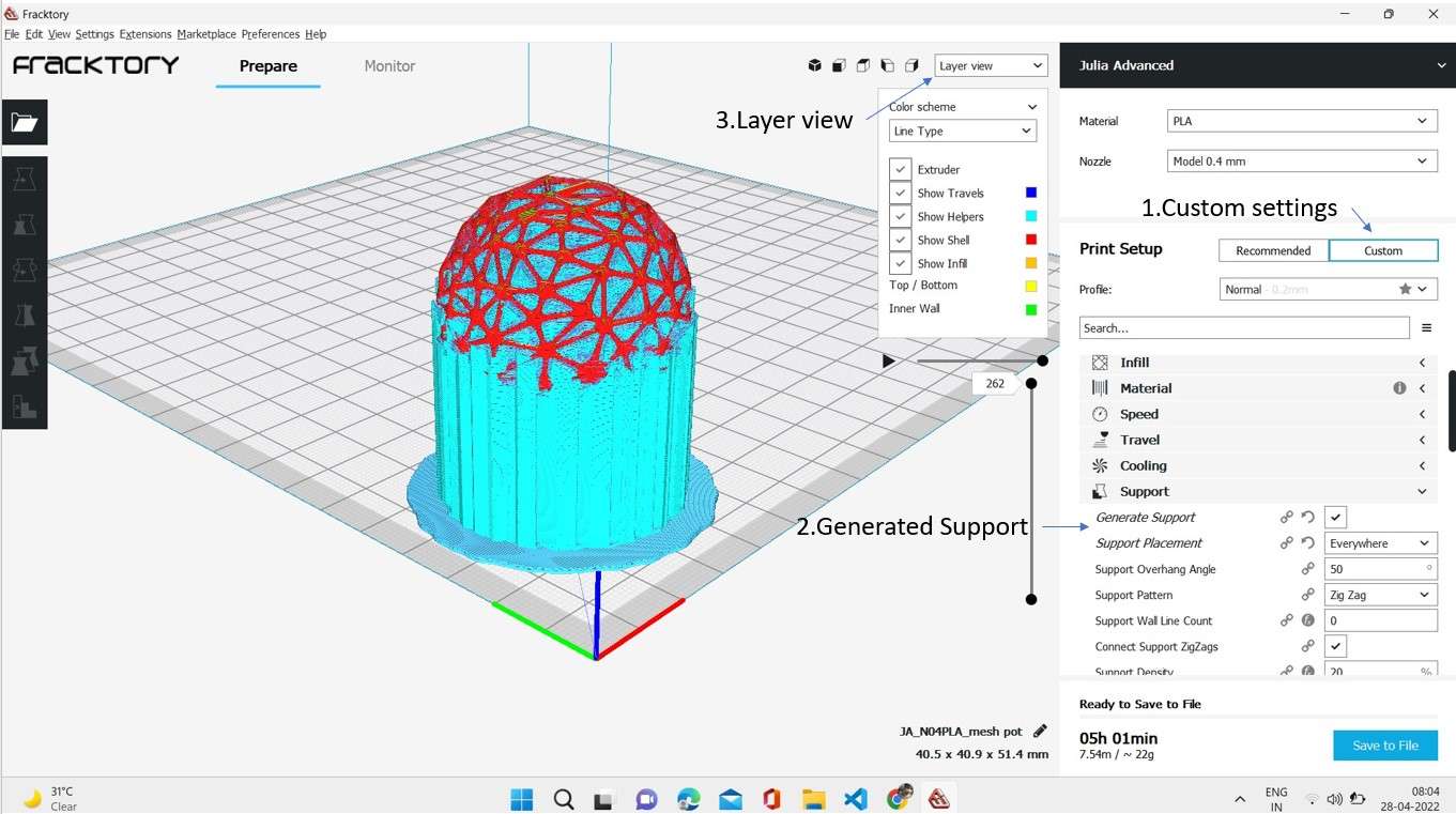
Generating the support .
This is what the print looks like after printing with support. As you can see. I tried to remove support. but it was difficult somehow. After carefully removing the supports This is what I end up with. This one more trial again failed. This was my 3rd trial and I was completely upset and thinking of moving with another design.
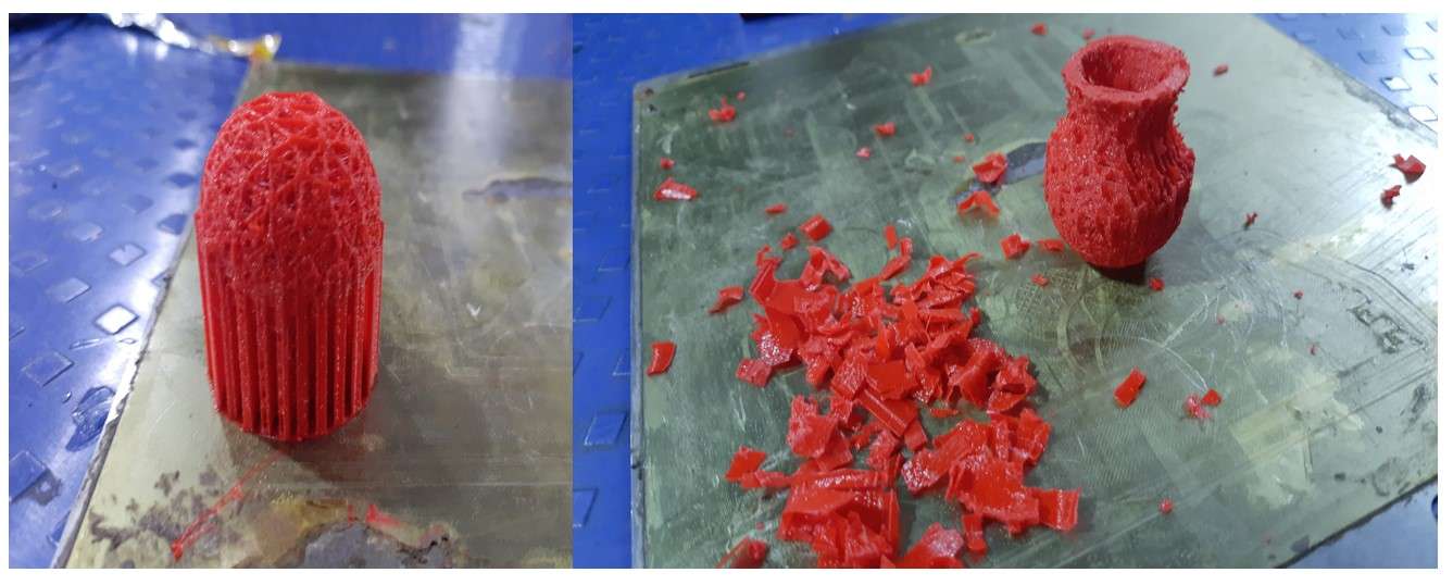
3rd try 3D print with support failed.
Print 4:Print with original size.
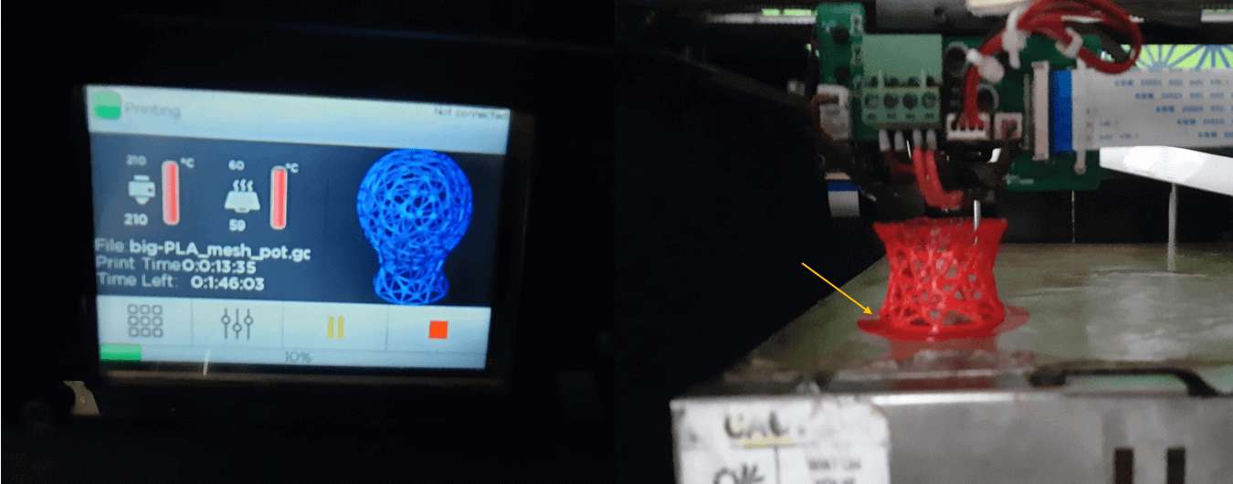
Before moving to another design the early next morning. I decided to one more last time printing the mesh pot once again. I live in all original dimensions Taking all the settings by default. As you can see. The brim support was as it is. With the print timing of 6.59hr printing timing. Hopefully, at that time, no one in our lab is working on 3D printing. I was lucky and the metrical object was the object printed perfectly. It was one of the best moments in the fab academy for me.seeing the object I design getting printed.
4nd time design with original size and setings as it was in my 2 trial.
This was the video during the 4th attempt at 3D printing. It was so exciting looking at the object getting printed finally after the previous failure.
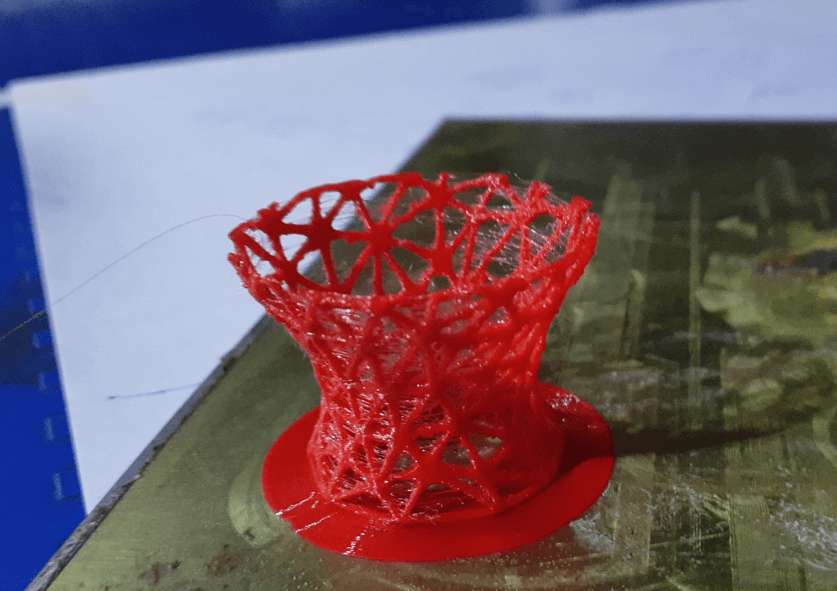
This is what the final complete print looks like.
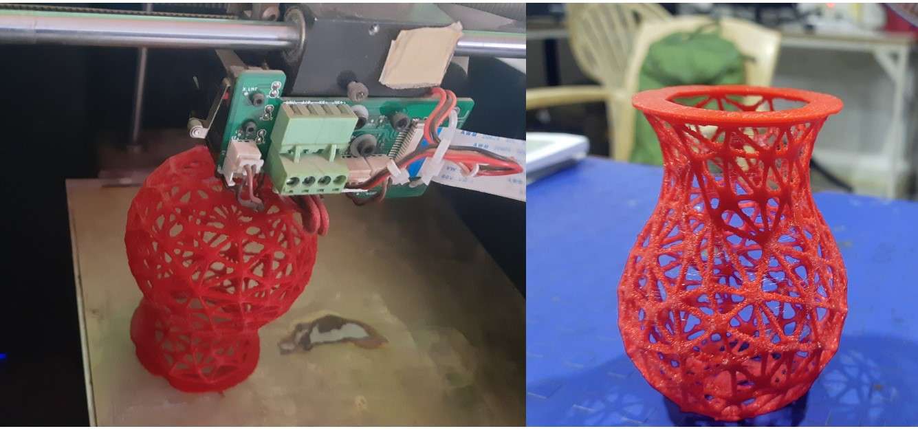
4nd time design with original size succefully printed 😍.
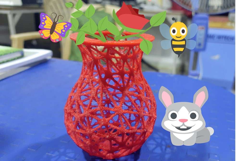
My favourite Hero shot of this Assigment.
Top Definitions Quiz More About Slow But Steady Wins The Race Examples Slow but steady wins the race .All my previous failures and successes are in one picture 😍.
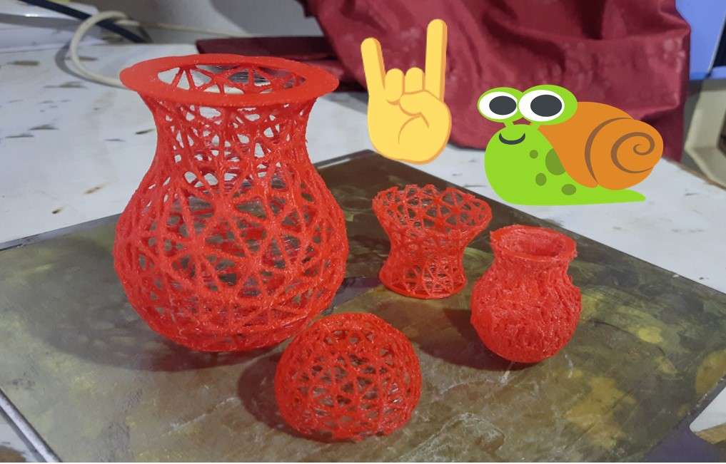
All attempt print in one picher .
A final hero shot with some images add in .
3D-Scaning :
A 3D scanner can be thought of as a sort of physical photography. By scanning a physical object, you can create a 3D digital model. Unlike traditional photography, however, you can use the digital model to return to the physical mode by sending the image to a 3D printer.3D scanner gives you the ability to observe a scene in three dimensions and then translate the observations into a 3D model.
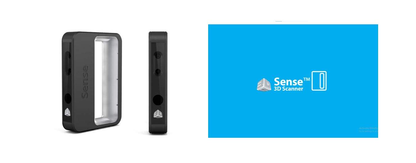
3D Sense scanner .
For 3D scanning I use a 3D Sense scanner for this assignment.
It comes with its integrated software 3D Sense scanner.
Click here to download the 3D Sense Scanner Softwar.
Click here to download the 3D Sense manual.
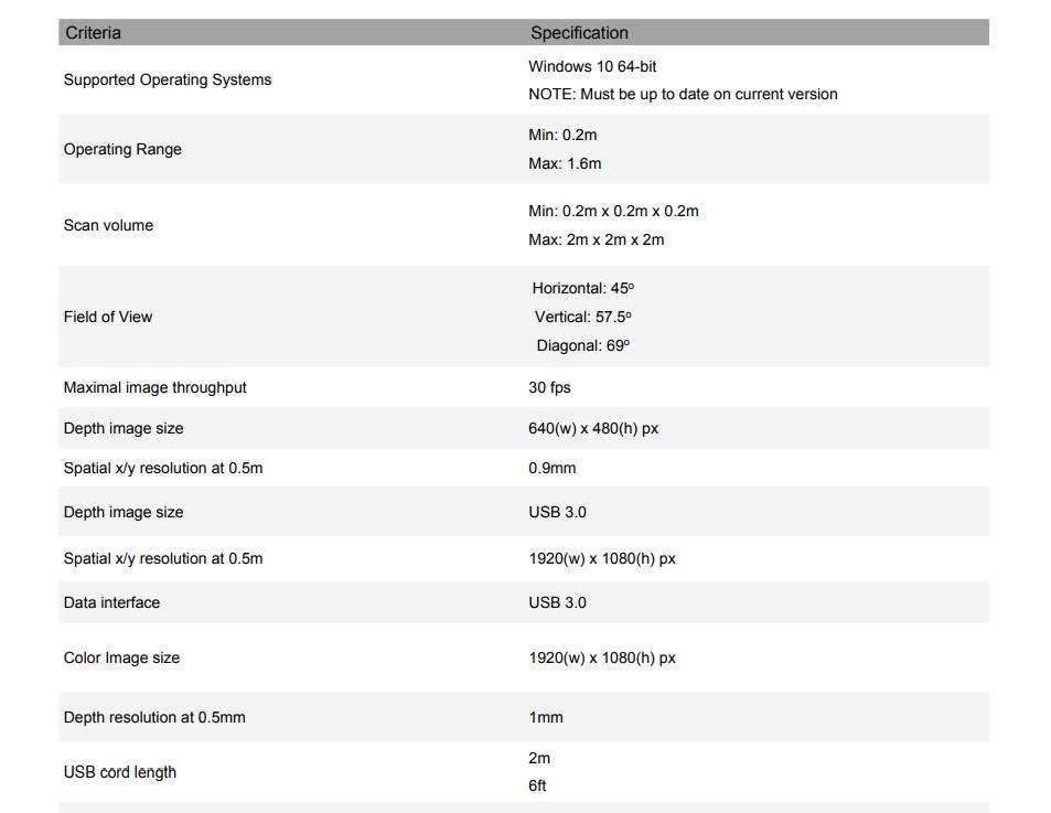
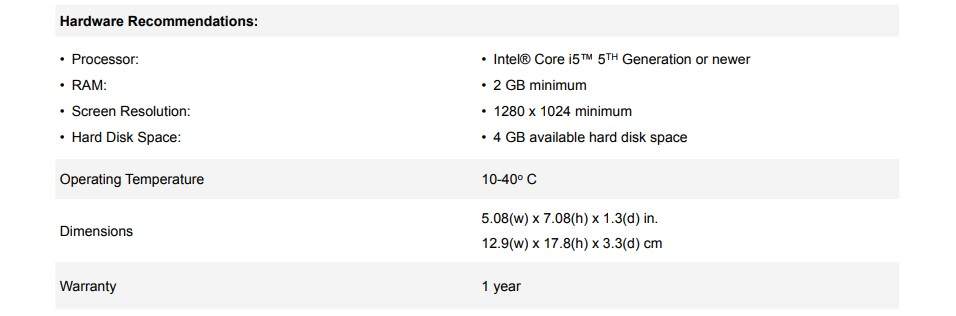
Features and Specifications:
.
Hardware Recommendations:
.
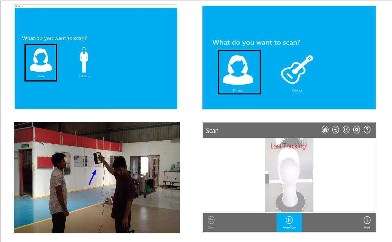
3D Sense scanners have two modes in the software you can either scan an object or a human .I scane my self and also help my friens to scan them using this scaner.
.
Scaner loss track was the common error we all face during the scaning process .The scane model is saved in OBJ file dormate .which I fearther open in AutoDex Mesh mixer to edit the edjes by using its sculpture tools and extract the OBJ file formate to STL file formate .
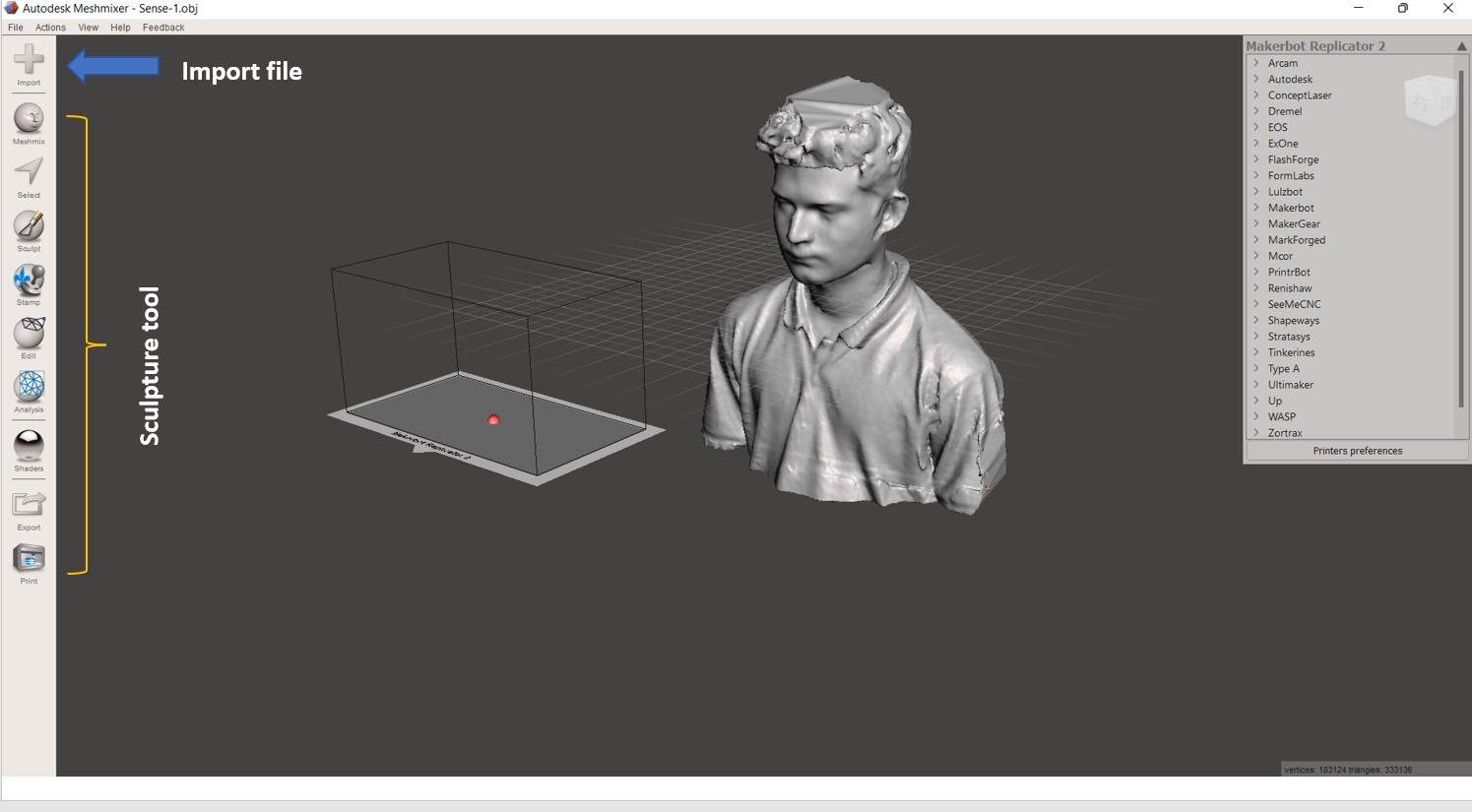
Import obj file in AutoDex Mesh mixer.
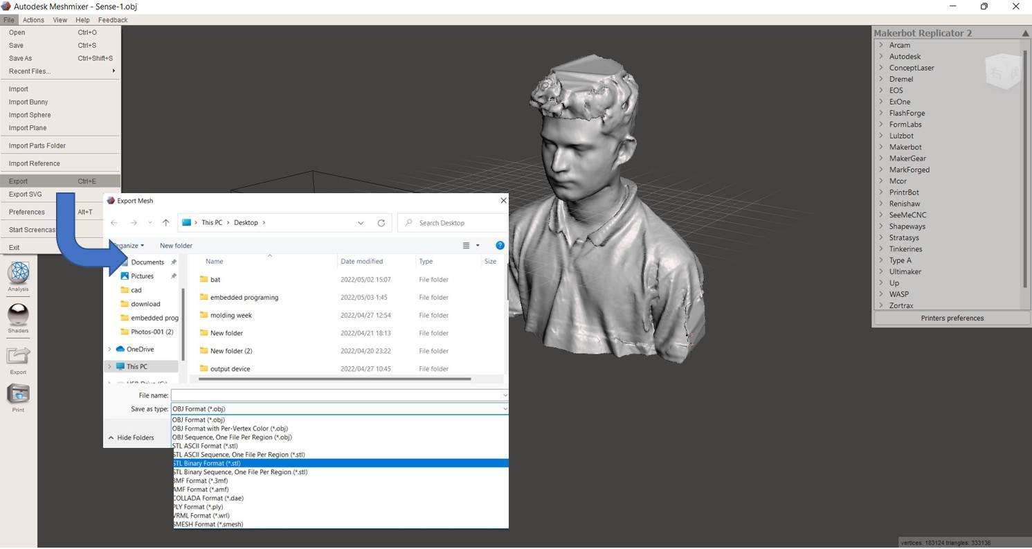
Exporting STL file formate.
This one is the by 3D Scan sculpture of my self I uploded on skechfab .
I use fractory works softwere to generate the G-code file for 3D printing.
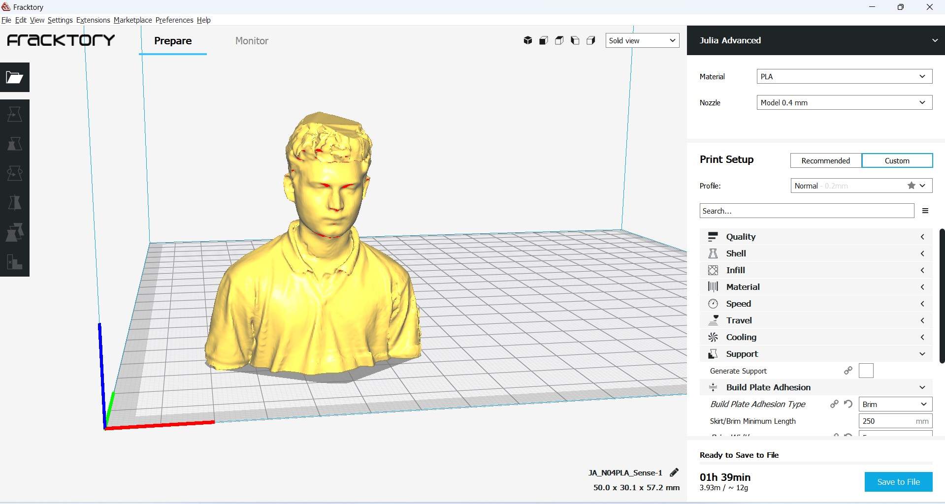
Generating G-Code file.
and this is the 3D printed sclpture .
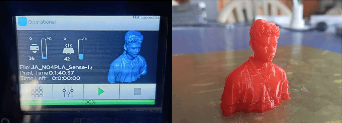
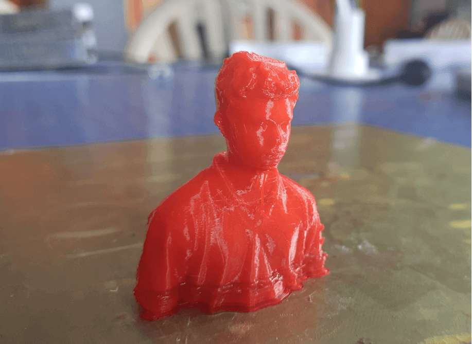
3D printed sculpture.
Heroshort .
.