The task list for this week:
- Design and produce something with a digital fabrication process (incorporating computer-aided design and manufacturing) not covered in another assignment.
CNC Plasma cutter :
CNC Plasma cutter.
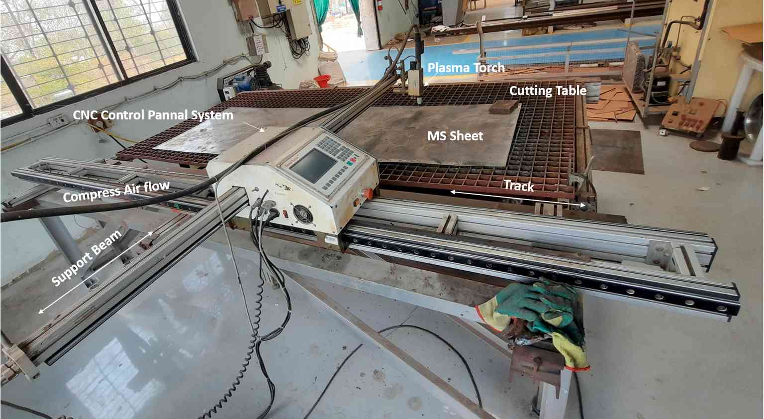
I use a CNC plasma cutter machine in our workshop to make a Body Frame for my project.I am already familiar with this machine and did a quit work with it during my fellowship program at Vigyan ashram in DIC (Design Innovation Center). I also fabricate my last Version of the Incinerator body using this machine. For this week I decided to make a design for my project and cut it using the plasma cutter using a 1 mm MS sheet. Thanks to Punesh he was with me and he help me a lot to make the whole assembly. It was not possible without him.
The specifications of CNC are as follows:
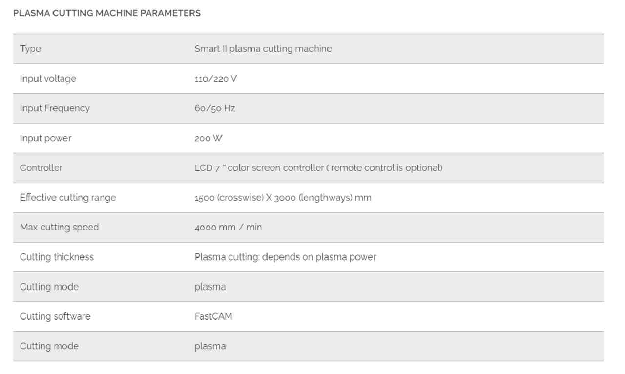
CNC Plasma cutter specification.
The CNC plasma cutter we have in our workshop is not completely bout out from a single manufacturer. So it is difficult to find out the specification surly.
Individual assignments:
Designe:
For this week I decided to work on making an Ashtray for my Final project Incinerator, As All the body frame was already cut by Purne and me previously. And we just left with the last part of our project i.e. Ashtray which will collect the ash generated after the incineration of pads.I fabricate the part in sheet metal and for that, I use the sheet metal section of Solidworks design software and its various features in my design as fallow:Part Drawing:
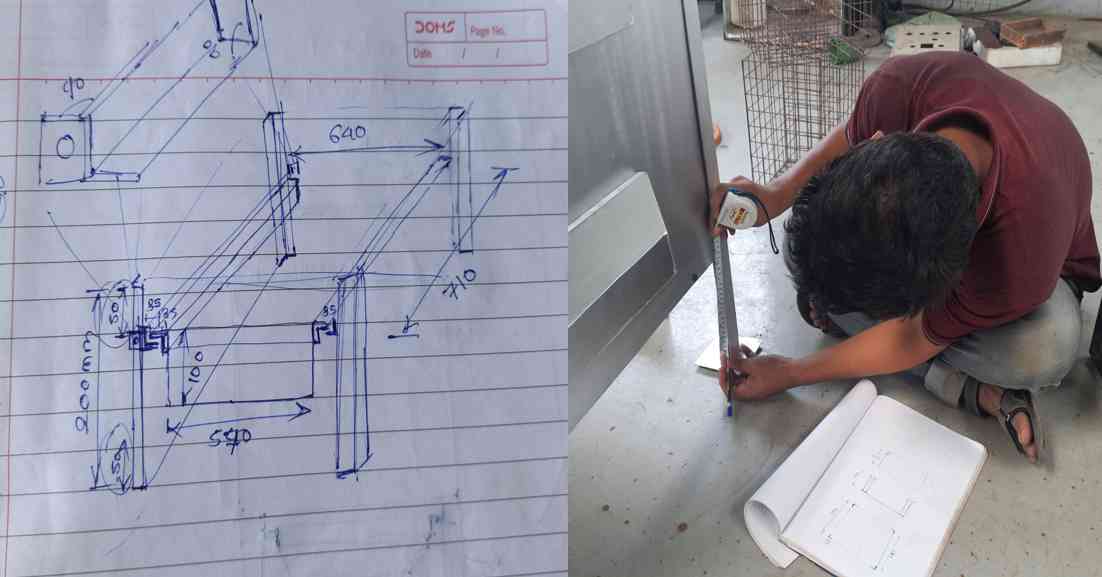
For making the design of the Ashtray. I follow the Design Thinking process, which we usually follow in DIC. I search the matter we have available. and think through users' perspectives and gather designs in my thinking. and draw it on paper.
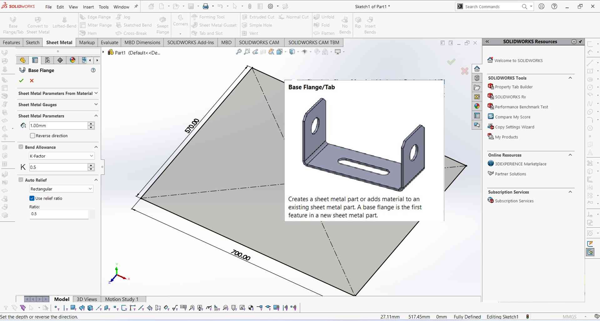
Base Flangg /Tab (Sheet metal designing)
1. It's easy for designing something when you have drowned on paper first. I stick to the design shown in the last image and start with a sketch in the solidworks window. After I enter in Base flange/Tab to convert my sketch into a sheet metal part of 1mm thickness.
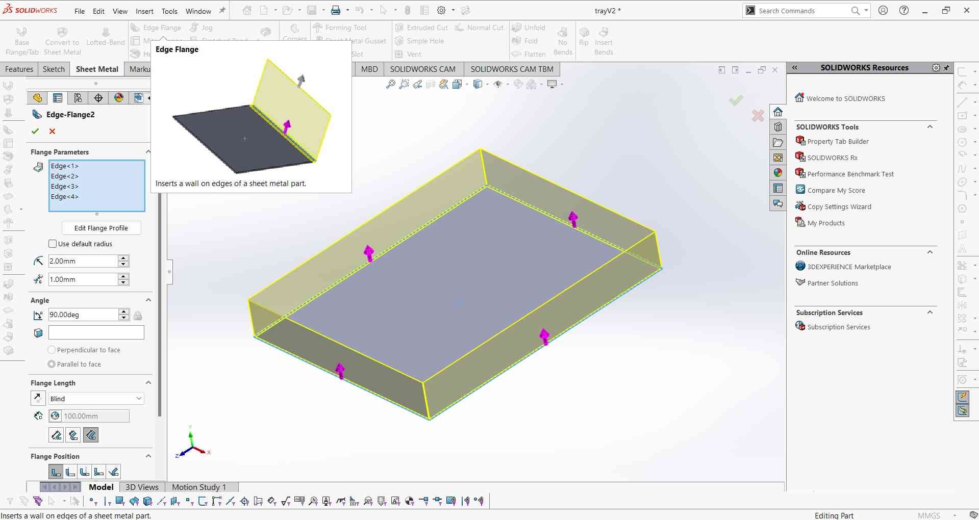
2. To give it a shape like a tray I use the Eagle Flag command and provide it with a tray-like shape.
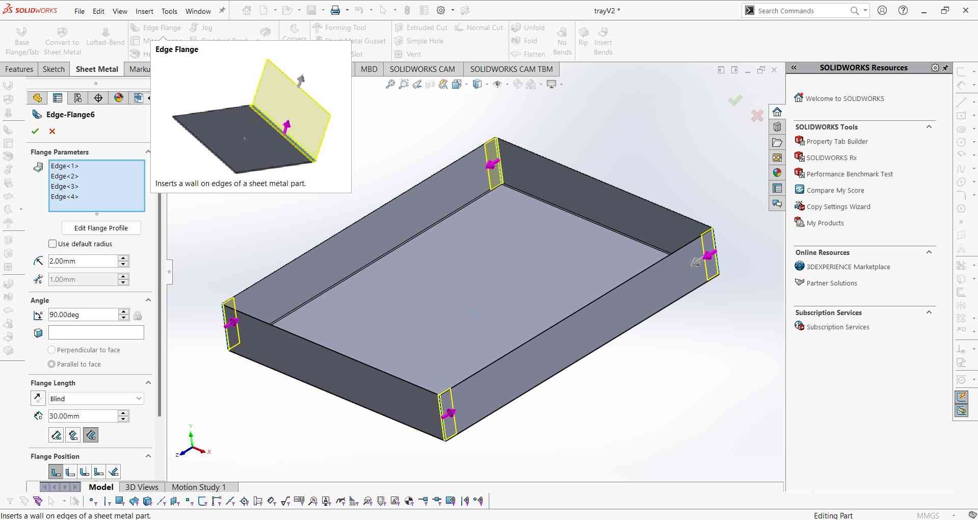
3.2nd time use the flange command to overlap the surfaces at each of four corners. So it will be easy to spot weld.
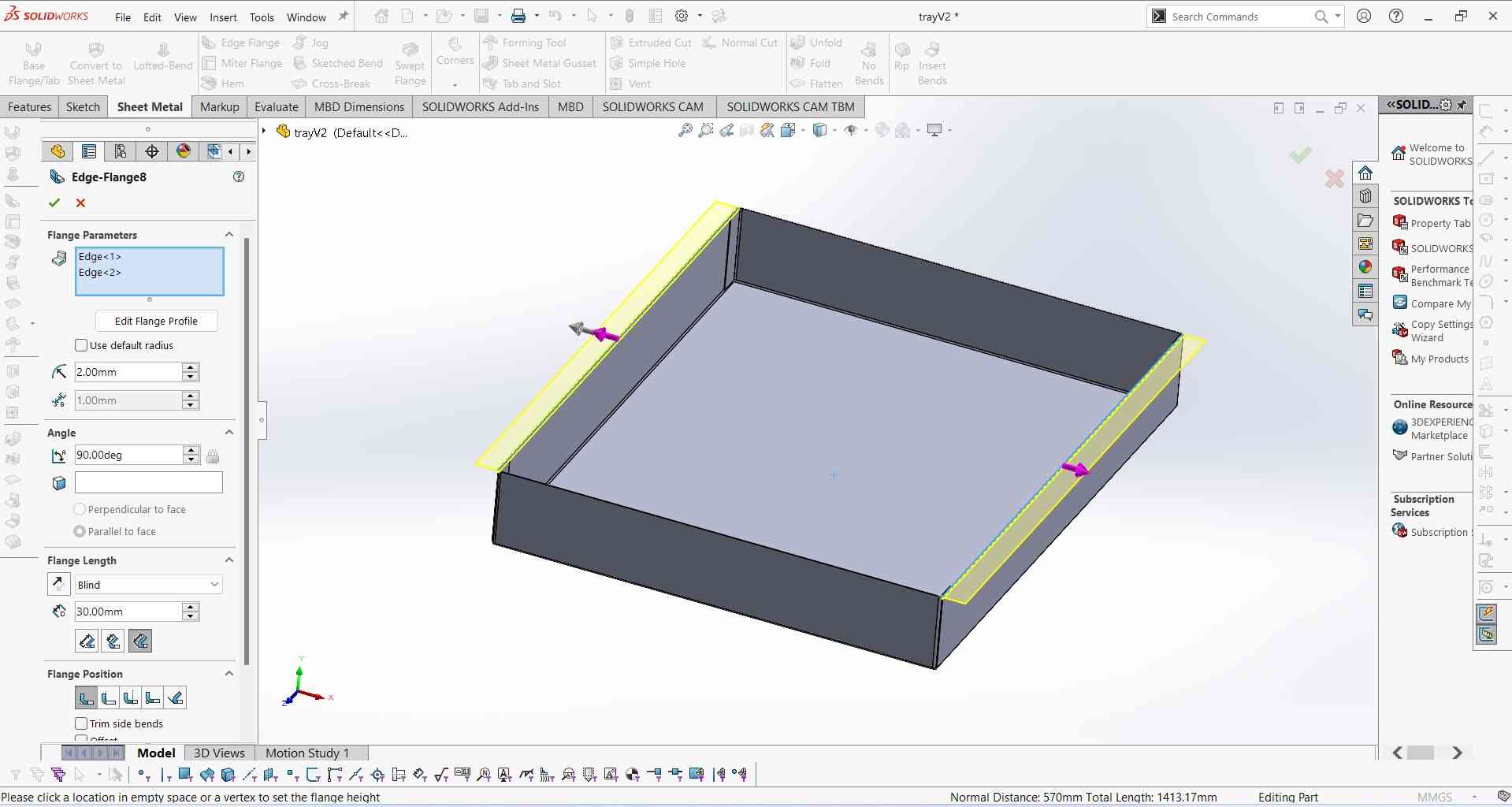
4.3rd time flang command to make a Support guide for sliding.
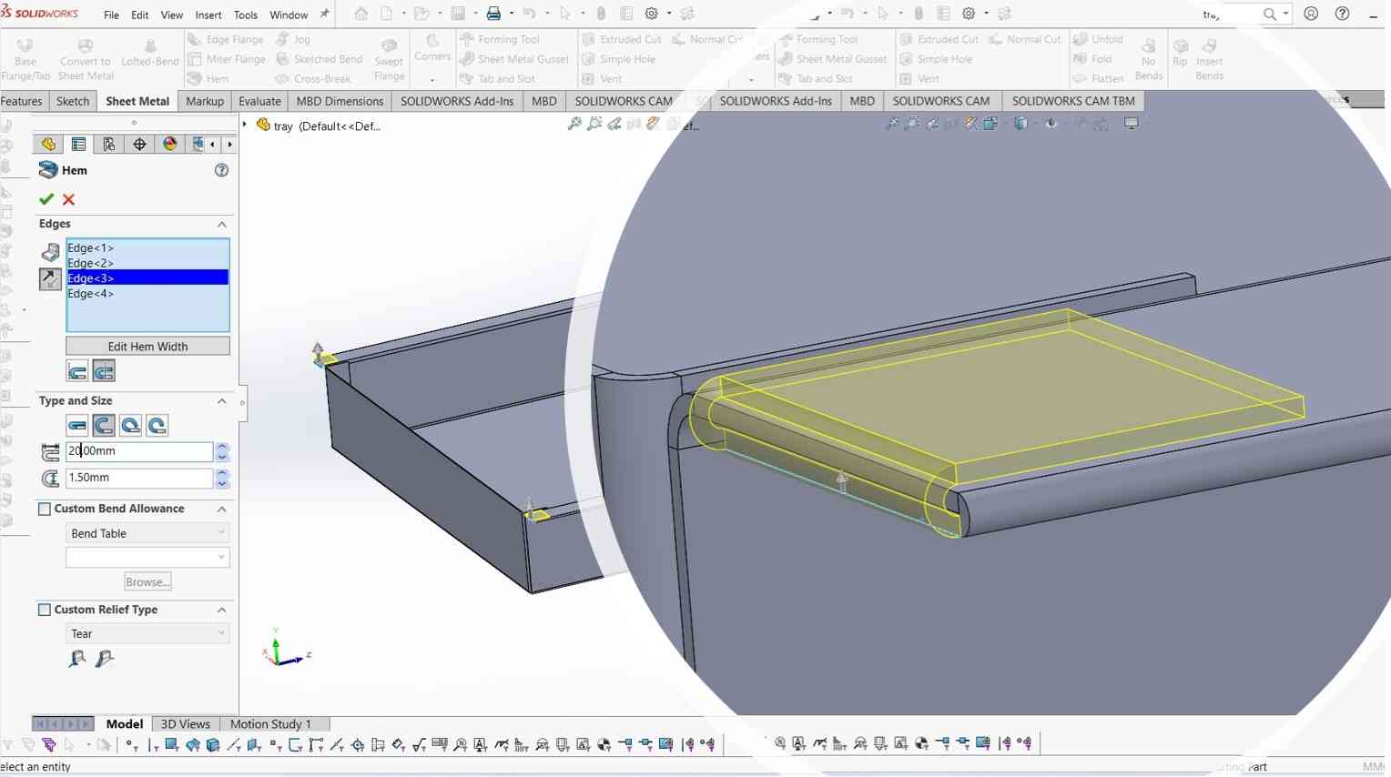
5. I use the Hem command to curl the sharp edges and make it an unsharp structure. It will help the tray to slight over the guide easily.
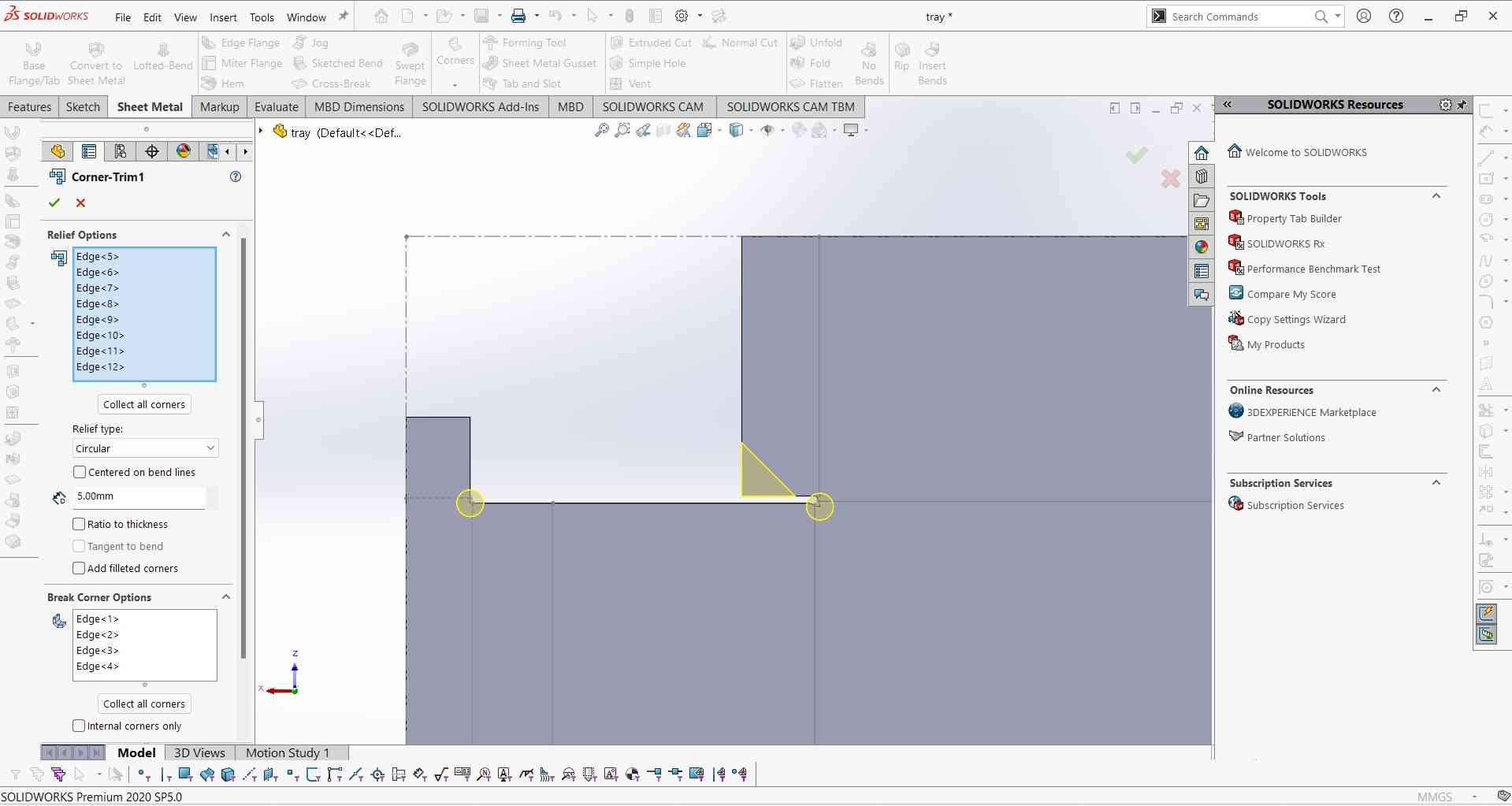
6. After this all. I thought my design is complete but it wasn't because after opening the folds using flatten command. I observe very sharp edges at each fold. So I have to do something for them.

7. For making the folding easier I got this option in the solid works sheet metal design section. Corner relief this command will make small circular holes at each folding corner. To make it easy to fold. same as dog bone in shopbot design.
8. I unfold it once again to see what it looks like after using corner relief and chamfering some unnecessary parts.
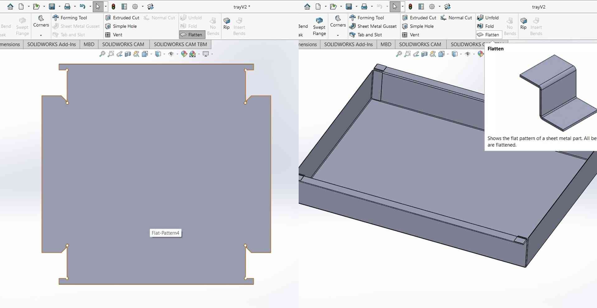
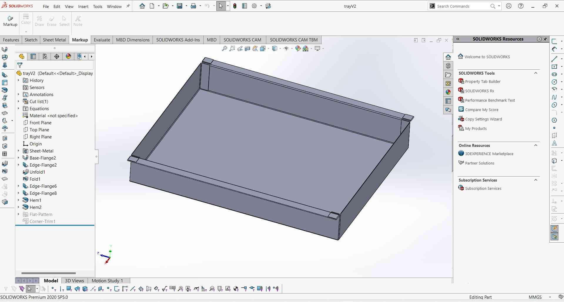
9. And this is what it looks like after fully designed.
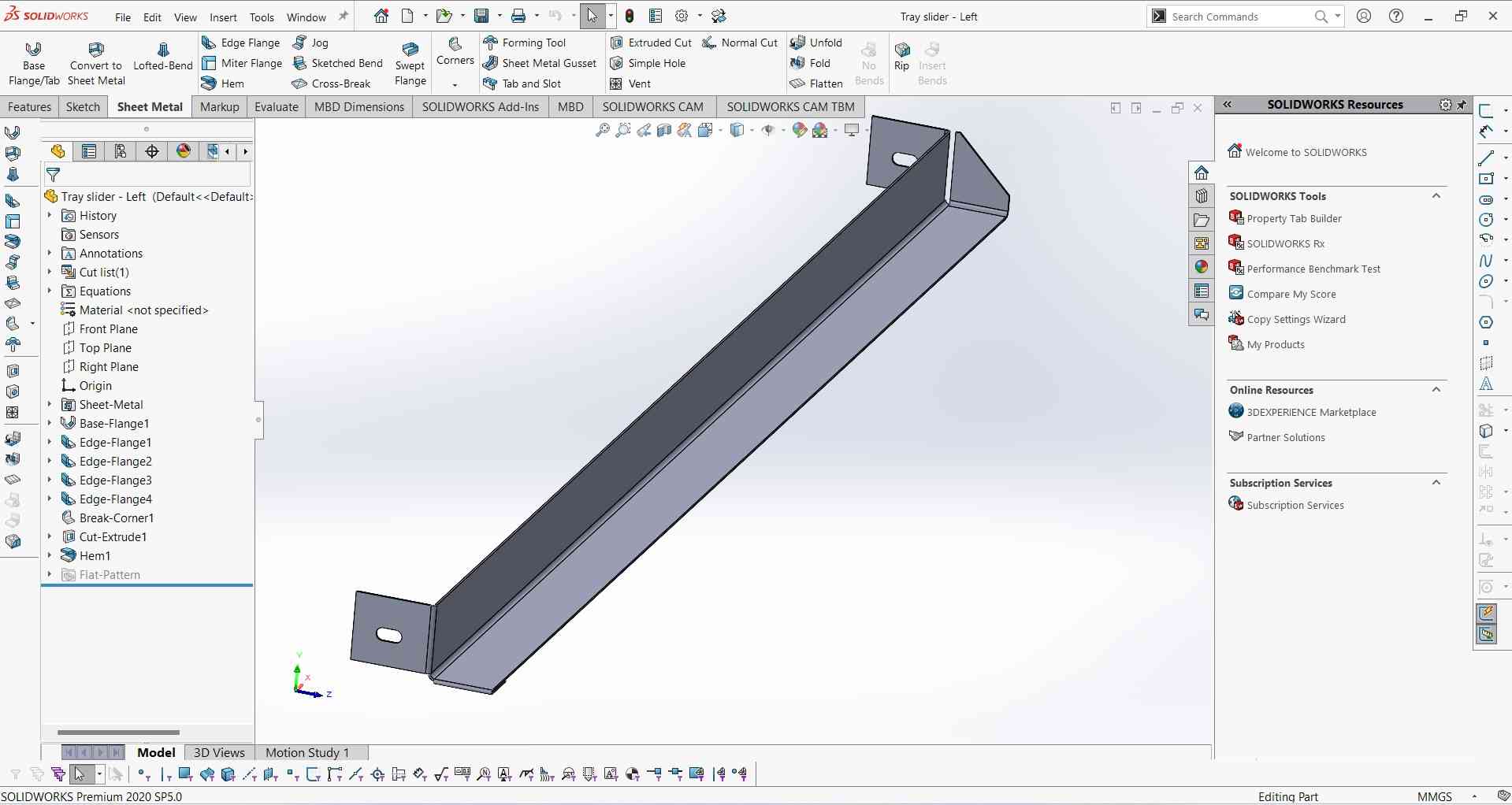
10. I also designe this guide way to support the tray during sliding.
Save as DXF.
After completing my design I unfold it and save it as a DXF format because FastCAM (Software use to generate G-Code for Plasma) requires a DXF file formate.
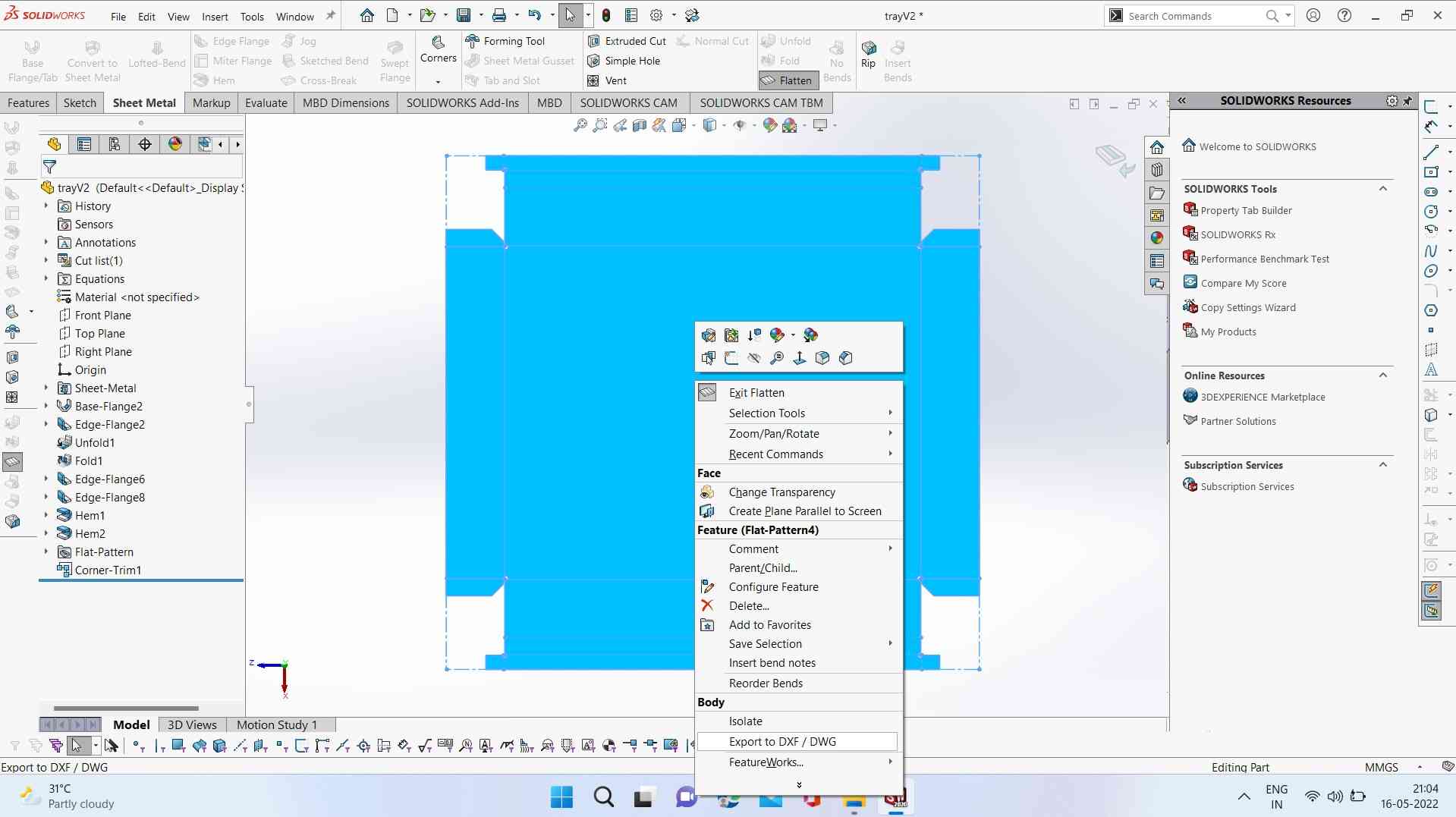
It's very easy to save a DXF file in Solidworks. Just with st the left click you will see a DXF option Click on it and it will save in DXF format.
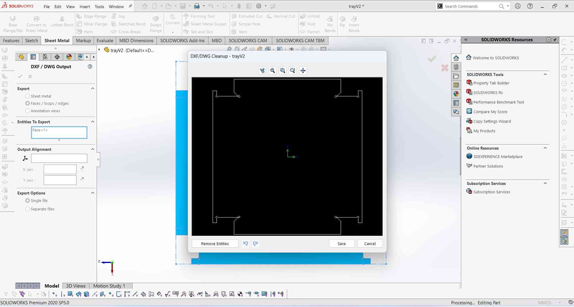
Note: To save a file in DXF format it is necessary it must be 2D. In my case, I select the unfolded surface of my design.
Creating Toolpaths.
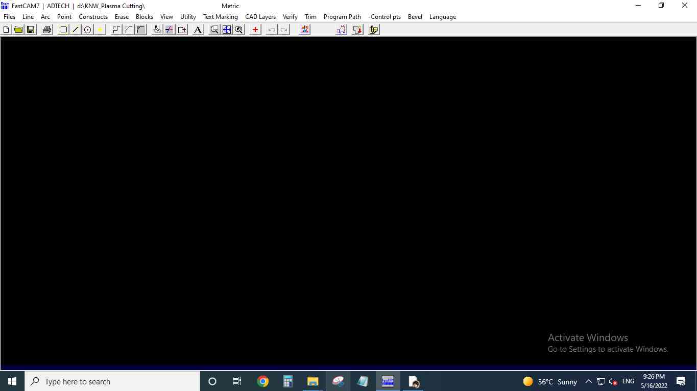
For generating the tool path for the CNC Plasma cutter. I use FastCAM. A FastCAM is a CAM software used for generating G-code files/tool path files for CNC Plasma cutter machines. It required a DXF file format to generate it. Below I explain how I use FastCAM (Paid software)to pull part DXF files and create a toolpath.
Step1.Open the FastCAM window.
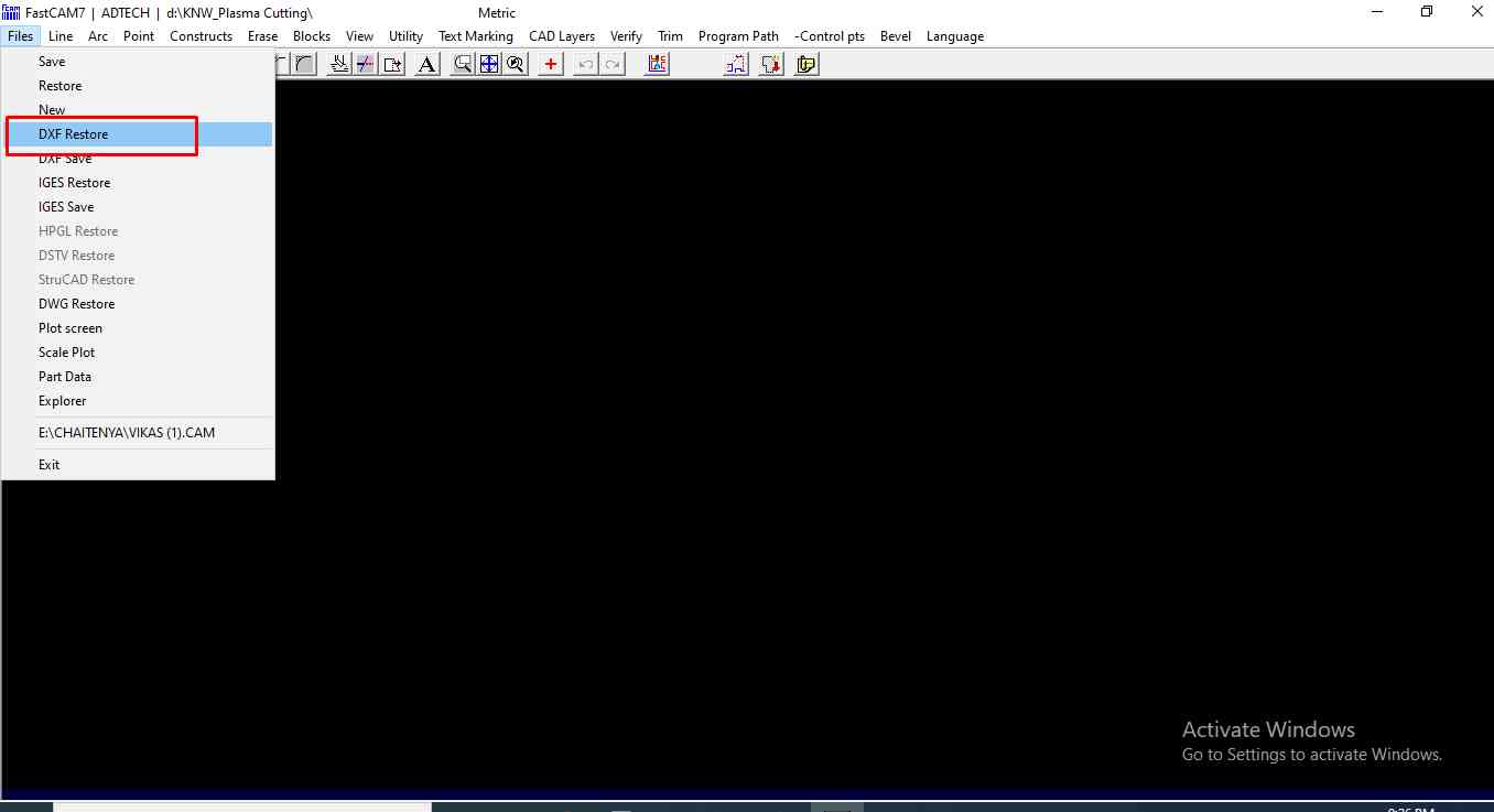
Step2.Import the DXF file.
.
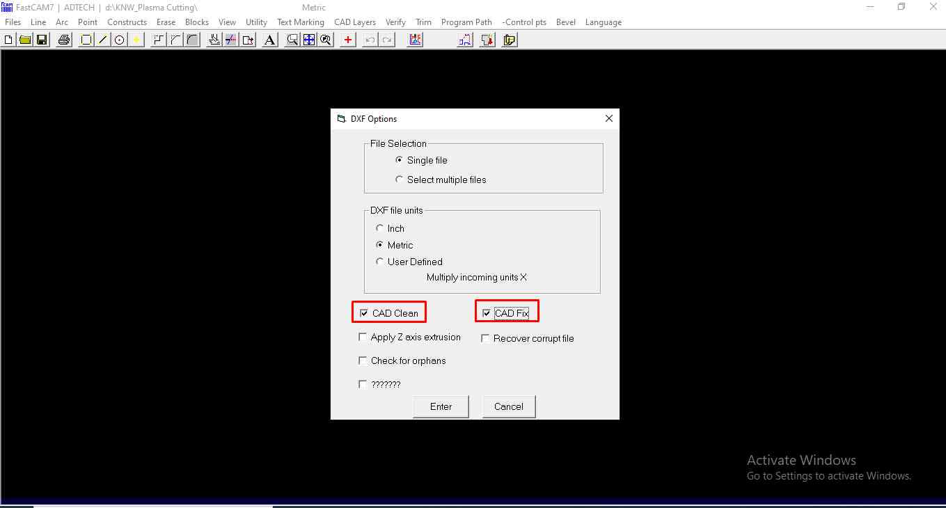
Step3.Select the units and file format+. which will define the dimension of the cut part. In my case, I use single file criteria and Units in Metrics as I use the same Units during designing.
.
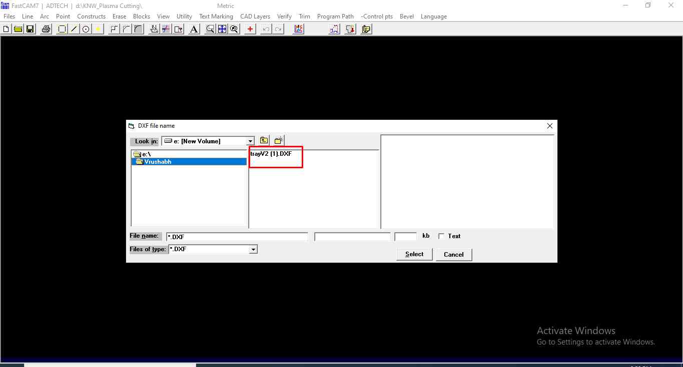
Step4.Now I open the folder and search for the file.
.
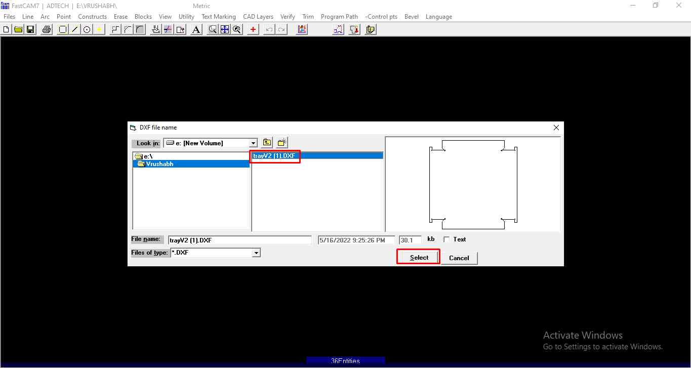
Step5.Select the DXF file.
.
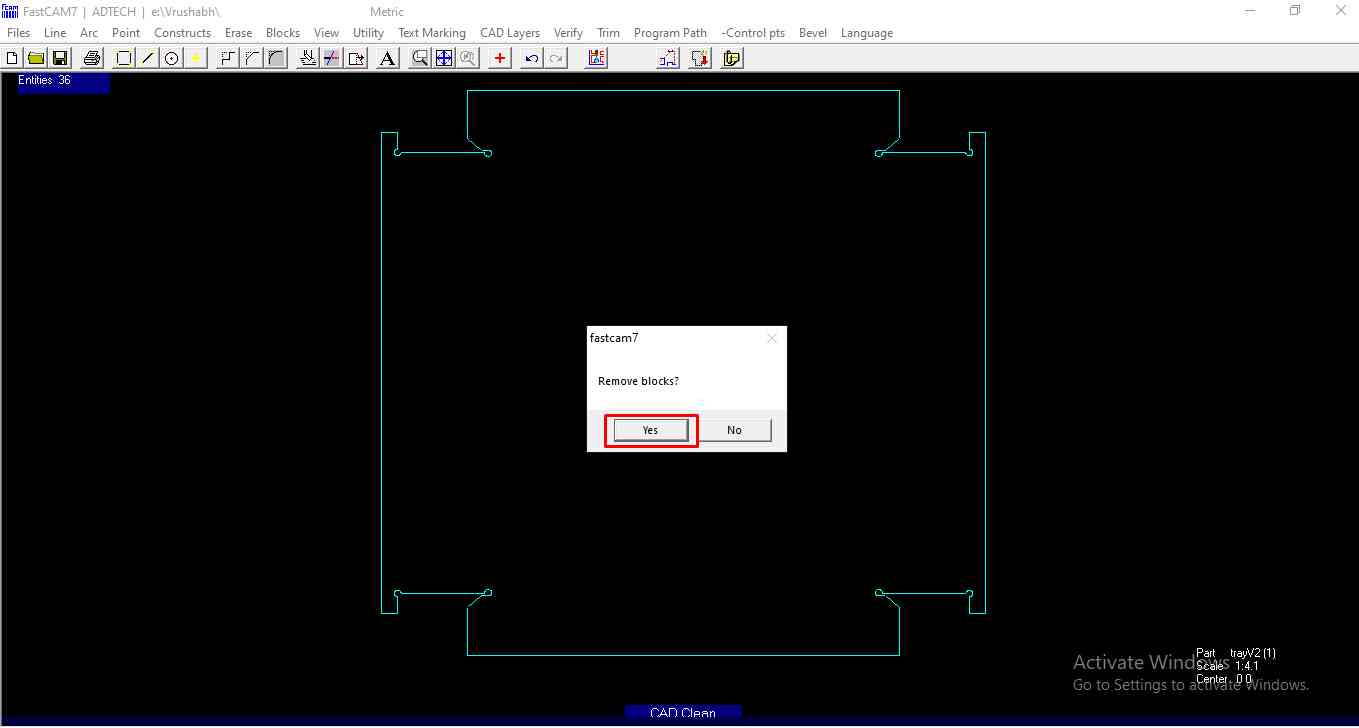
Step6.Now I don't what it was but I just click on remove the block. But the windows started to show the outline of the DXF file. I confirm it and go next.
.
Step7.To create the tool path. I go to the Program path>FastPATH.
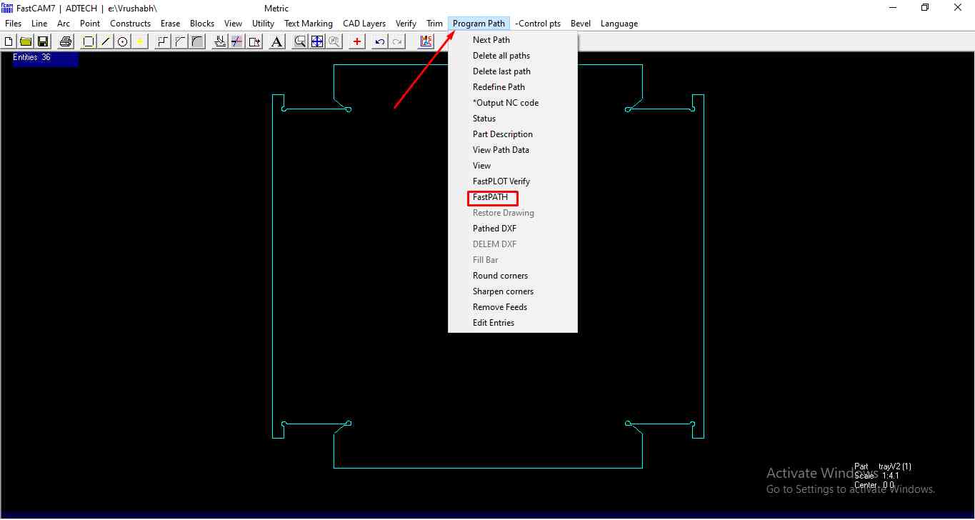
.
Step8.Then clink on Start FastPATH.
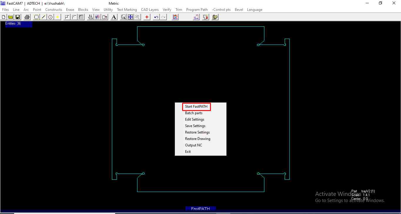
.
Step9.Now it shows the output in NC(numeric code)select ok and continue.
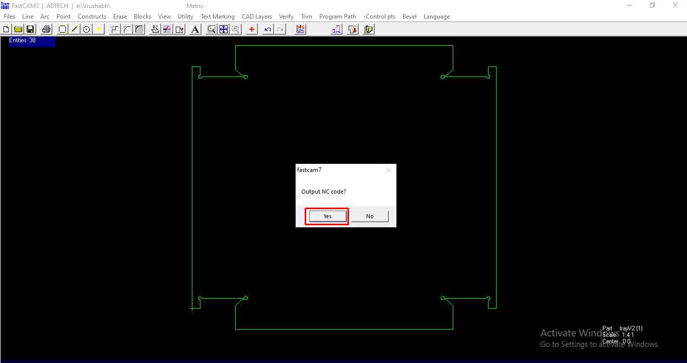
.
Step10:Now select the suitable folder and save it . It will save in text format. one can open the text file in Note Pad in windows to see the Numeric code and can Edit it if one knows the G-Code format after completing the process.
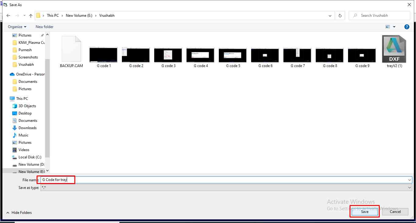
.
Step11.Now I have to define the origin .For that I click on the nearby suitable location. As shown in the image.
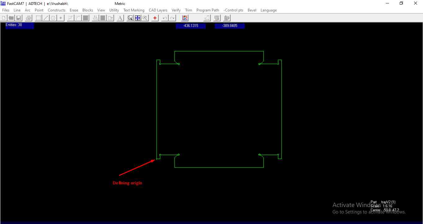
.
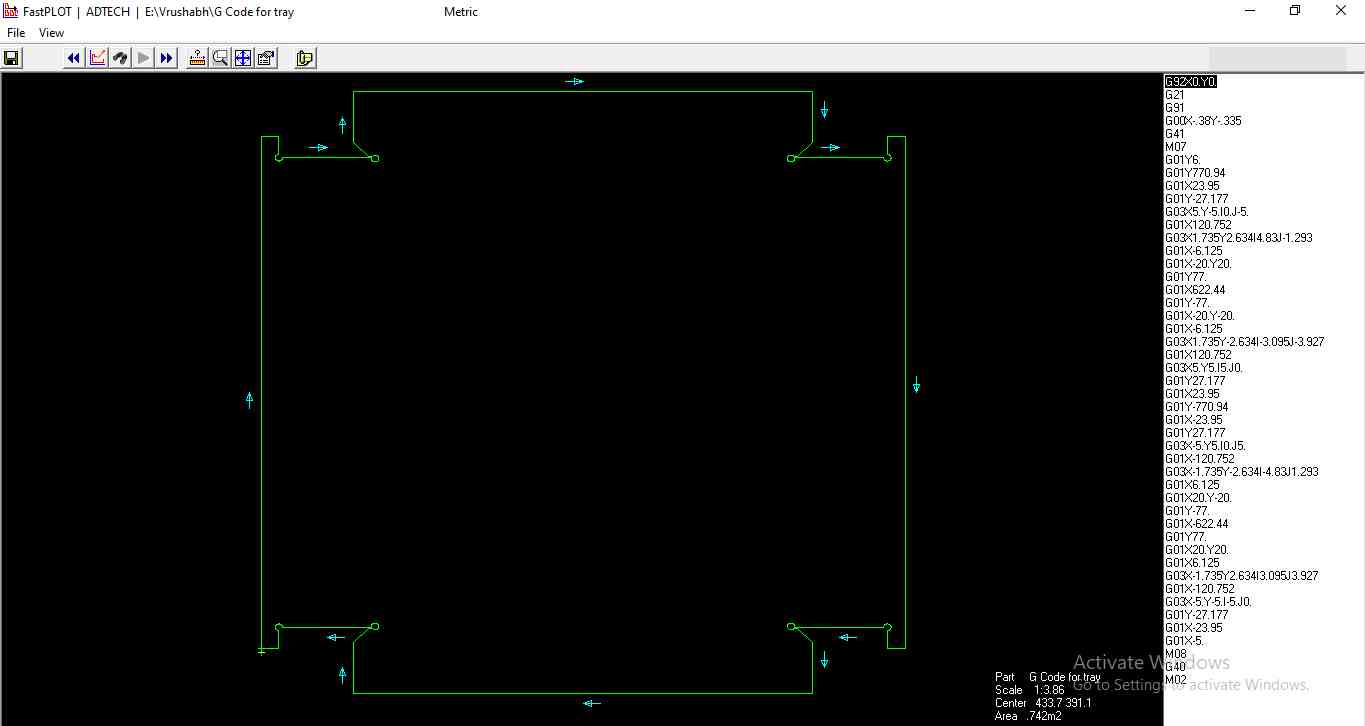
Step12.Now the G-code generation is complete you can see it on the extreme left of the window and can make changes too. The file will ve saved as per the location set in the folder.
.
Set up CNC Plasma for Cutting.
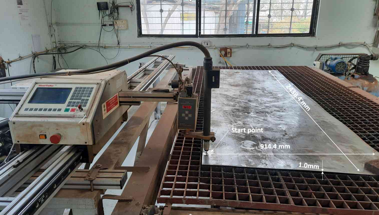
Loding the MS sheet on plasma bed.
I use a 3 feet *8 feet* 1mm MS sheet for cutting the sheet on plasma. It is huge and I will not be using an entire sheet for myself only. So during loading the sheet. I want to set it in a proper way .
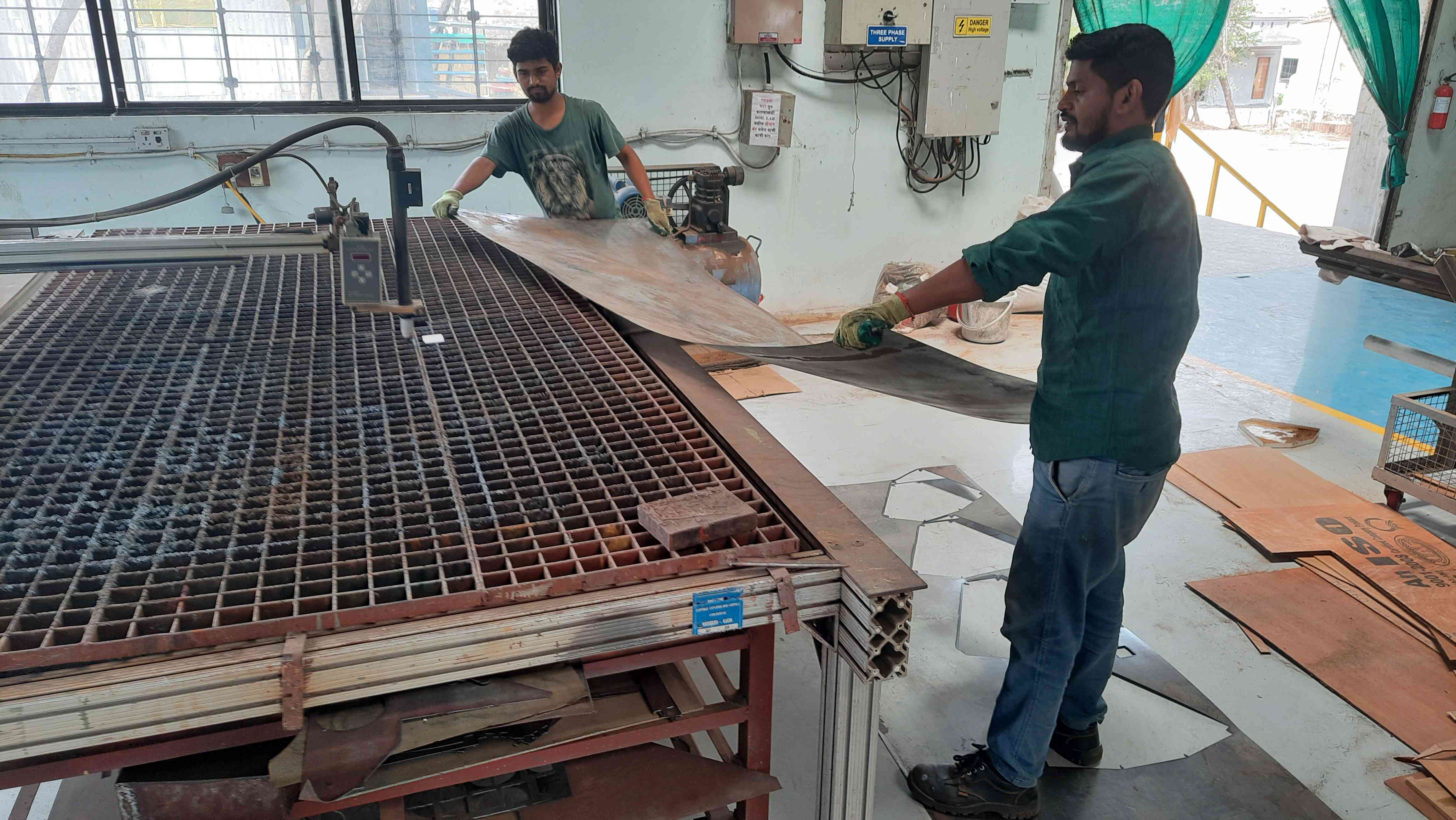
Loding MS sheet on Plasma Cutter bed.
Purnesh helps me a lot during all this procedure as it's not a one-person job. We follow the safety measures of the workshop as per the workshop Instructure. Where we keep our distance from machines. wear the hand glubs, and shop flower shoes that protect us.
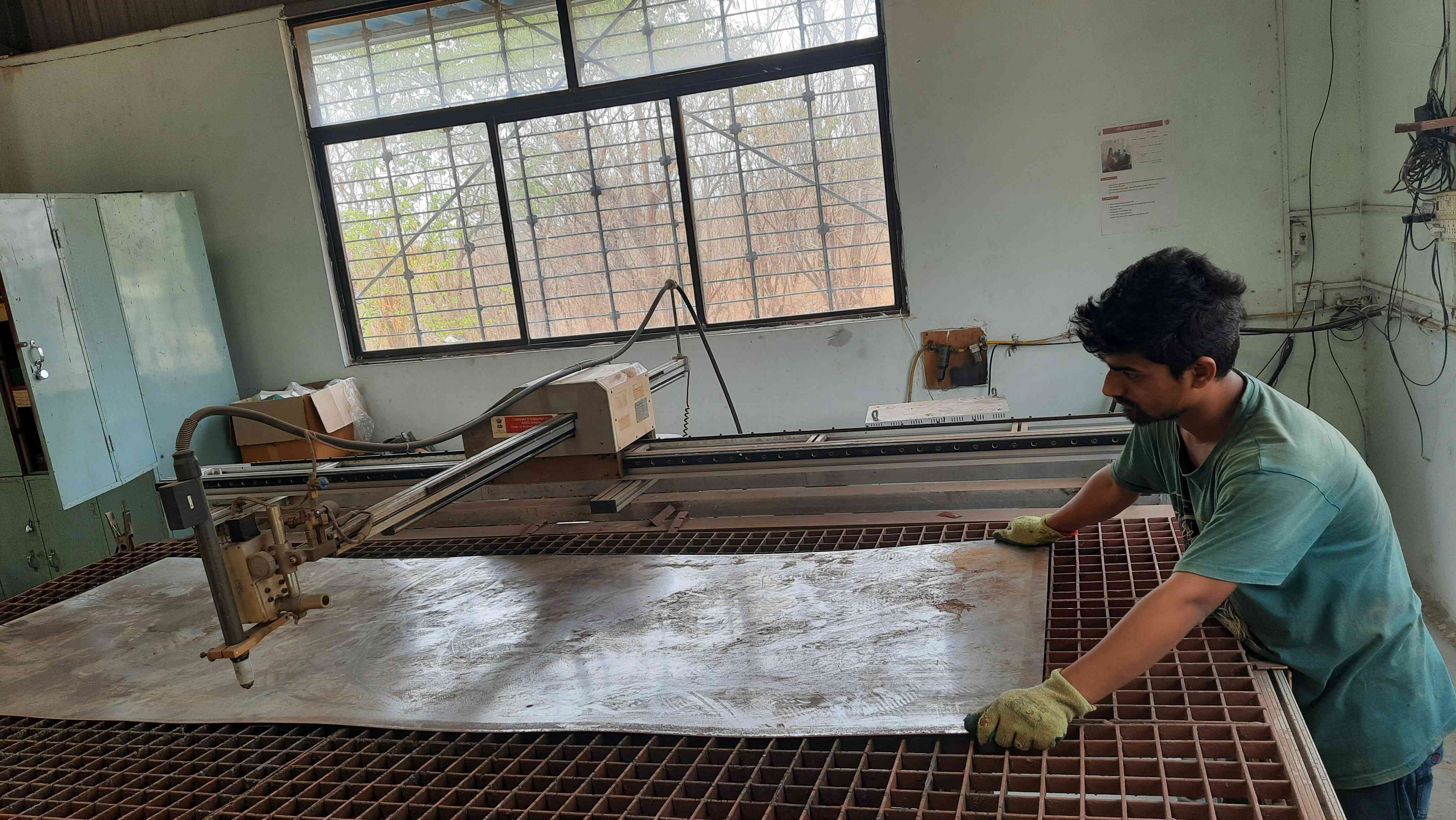
Adjesting the sheet on plasma according to job size.
Attaching GND to sheet metal.
It's important to provide proper GND to the sheet metal job. Because the plasma is generated due to the electric Arce and compressed air .So there must have a good GND connection for the generation of electricity Arc.
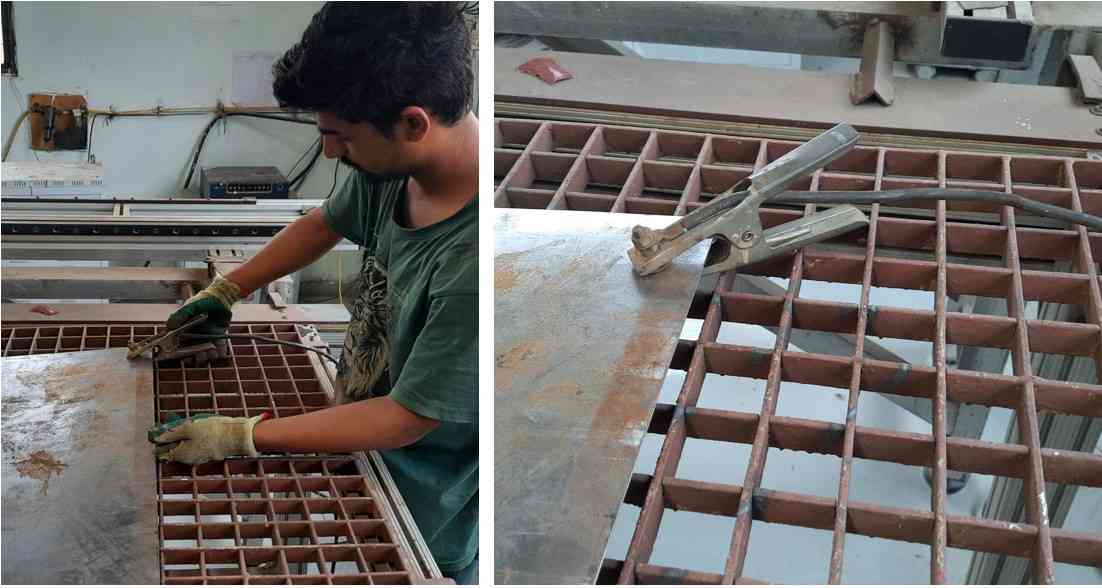
Clamp mounting to provide the GND.
Unlike every CNC machine in FabLab. Plasma cutters also want to define the origin.It has a manule operation button at controle panal .I set the origin manually just by moving it at desired position.
origin setting.
Cutting Sheet metal on Plasma cutter.
1.The CNC Plasma cutter in our workshop is operate on 3 phase supply. So for operating it is necessary to first check the supply meter .To conform the power supply .Othervise it will caue malfunctioning of machine during operation
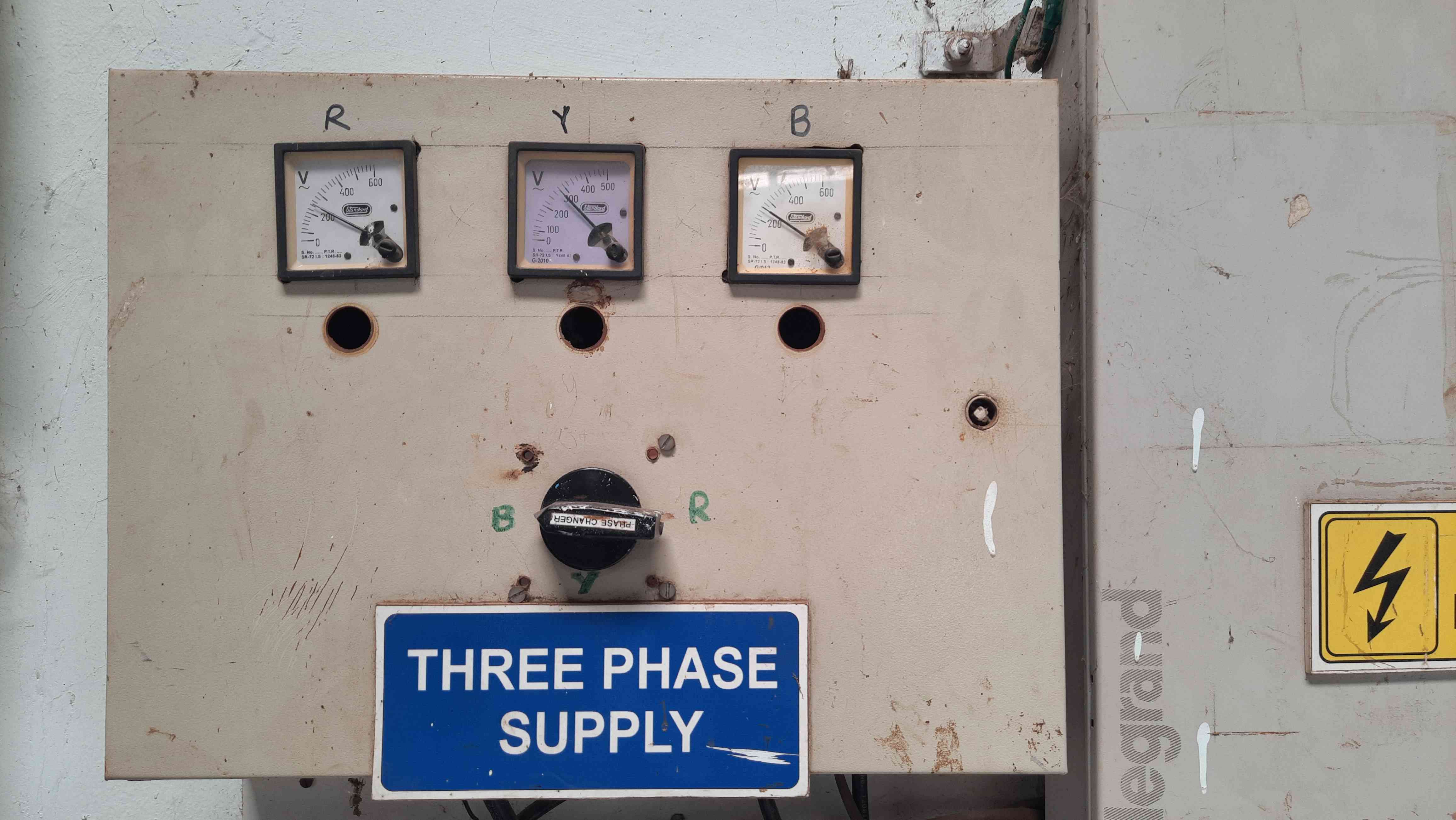
3 phase power supply meater.
2. The Next step is to turn on the Power supply for the plasma cutter. For that, I have to start the MCB.
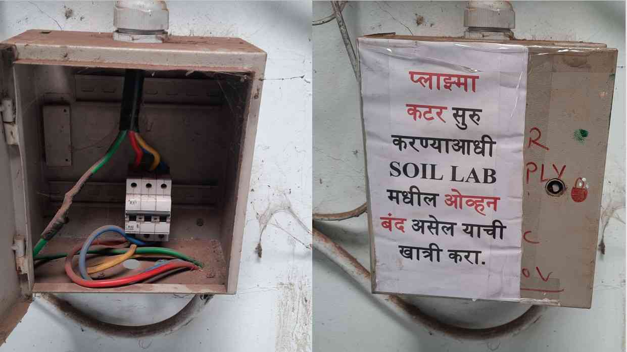
MCB switch for power supply.
3. To generate plasma. The plasma cutter requires Compress air as a medium with an electric arc. For that, we need to turn on an air compressor during cutting operation similar to LASER Cutter.
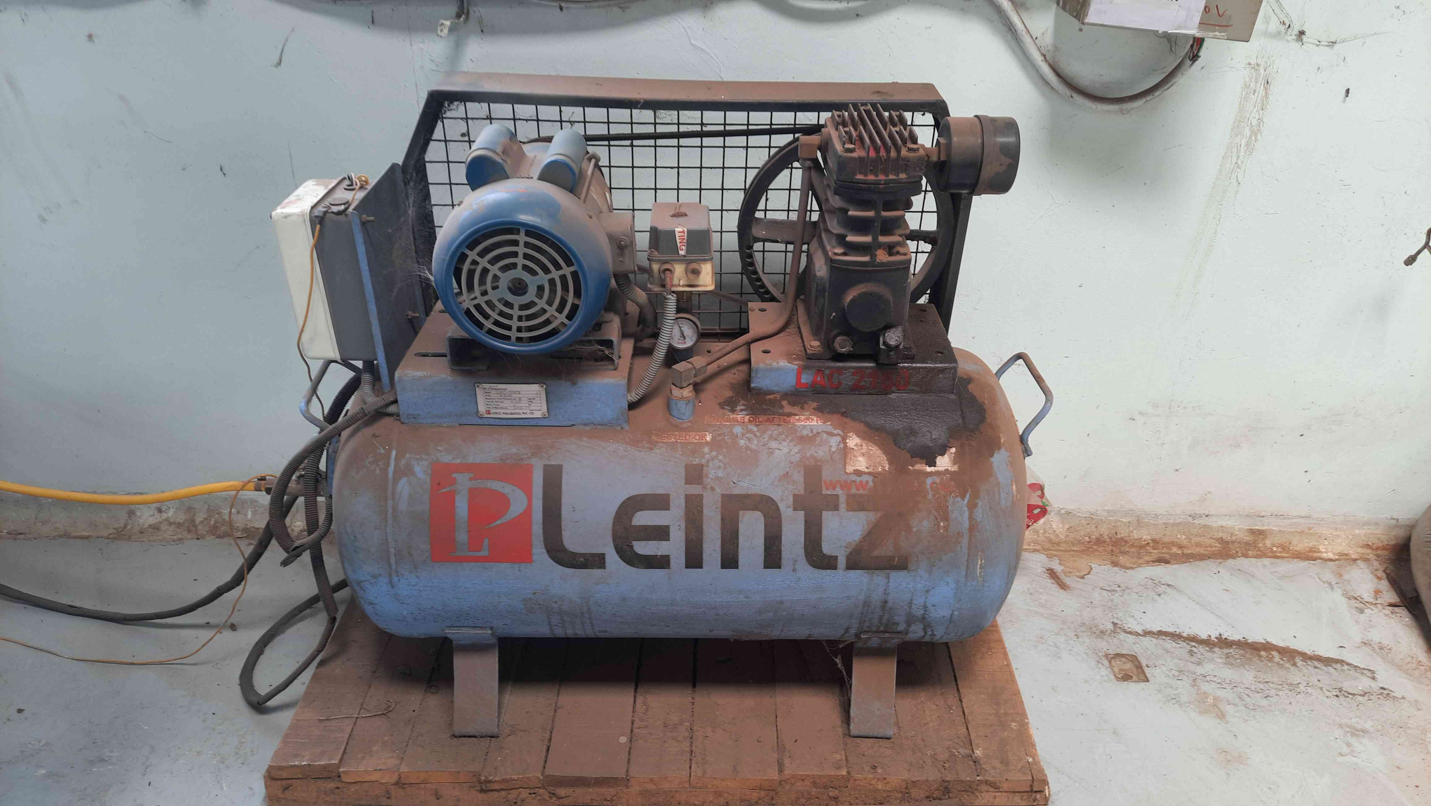
Air Compressore.
4. It is necessary to provide clean and dry air to generate plasma.For that one should need to remove moisture from time to time through moisture remover.
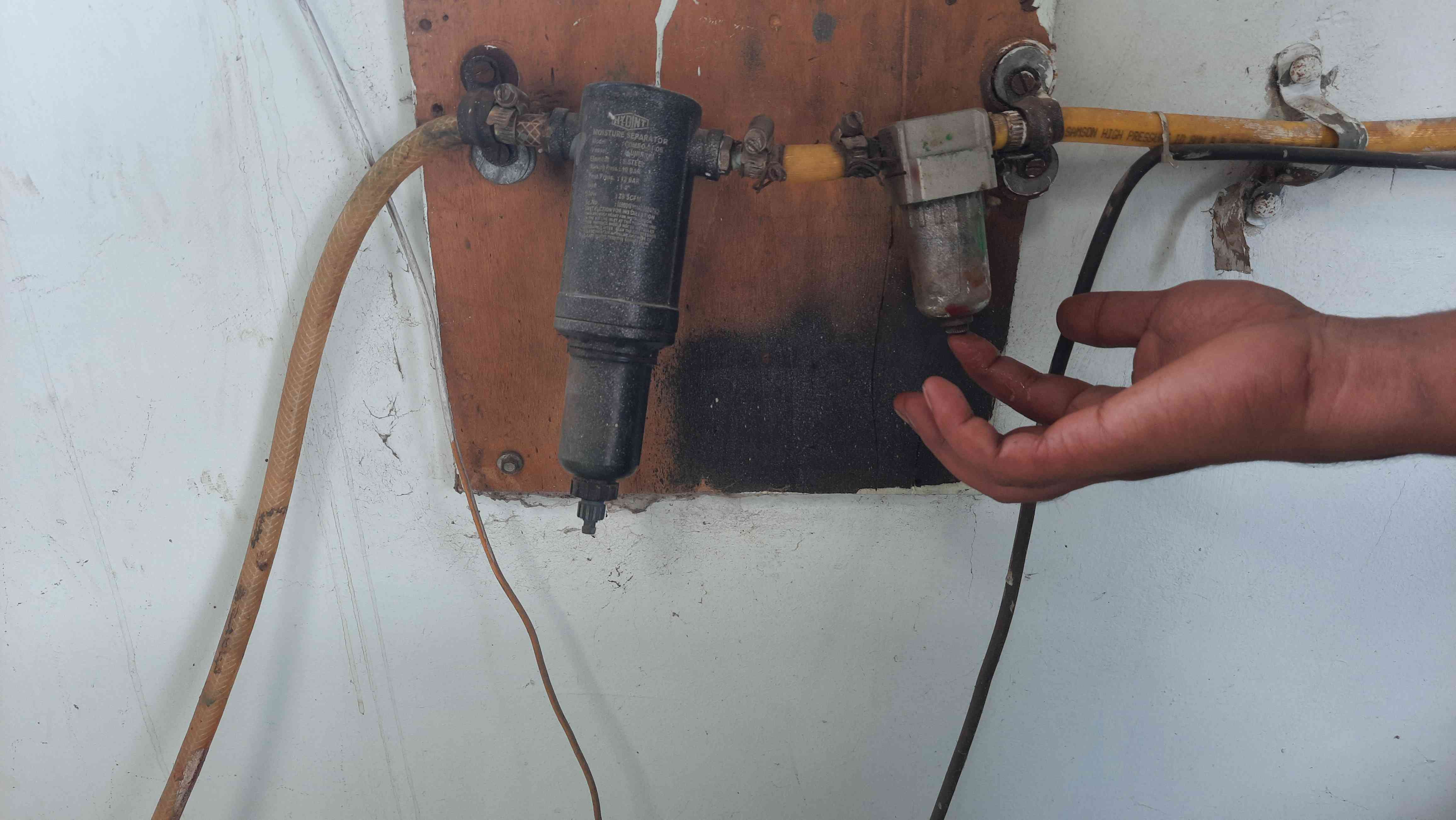
Moisture remover.
5. Now to turn on the plasma cutter turn on the plasma generator. It has the current adjuster. which you can adjust according to the thickness of the sheet and compressor pressure indicator.If all is good the plasma will work properly.
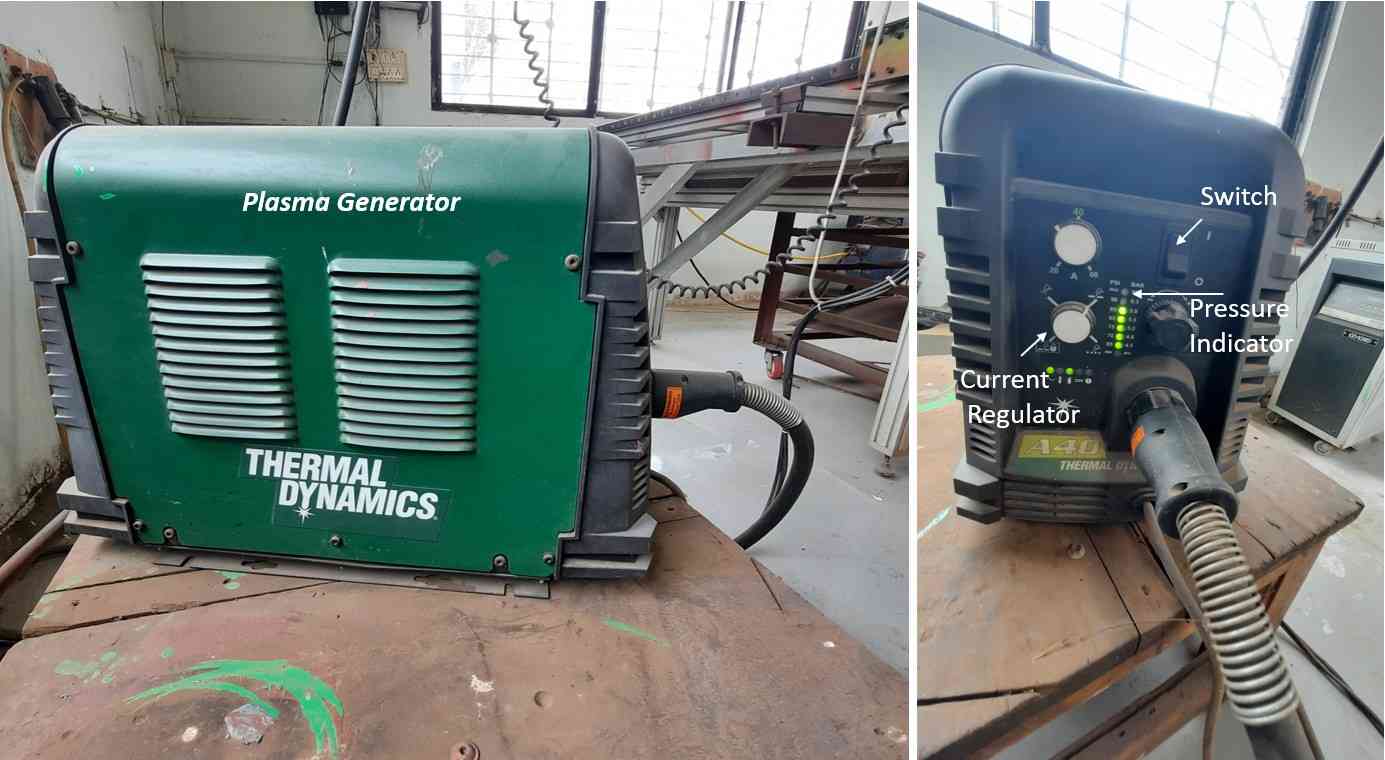
Plasma generator.
6. Now finally turn on the Control panel to start CNC.
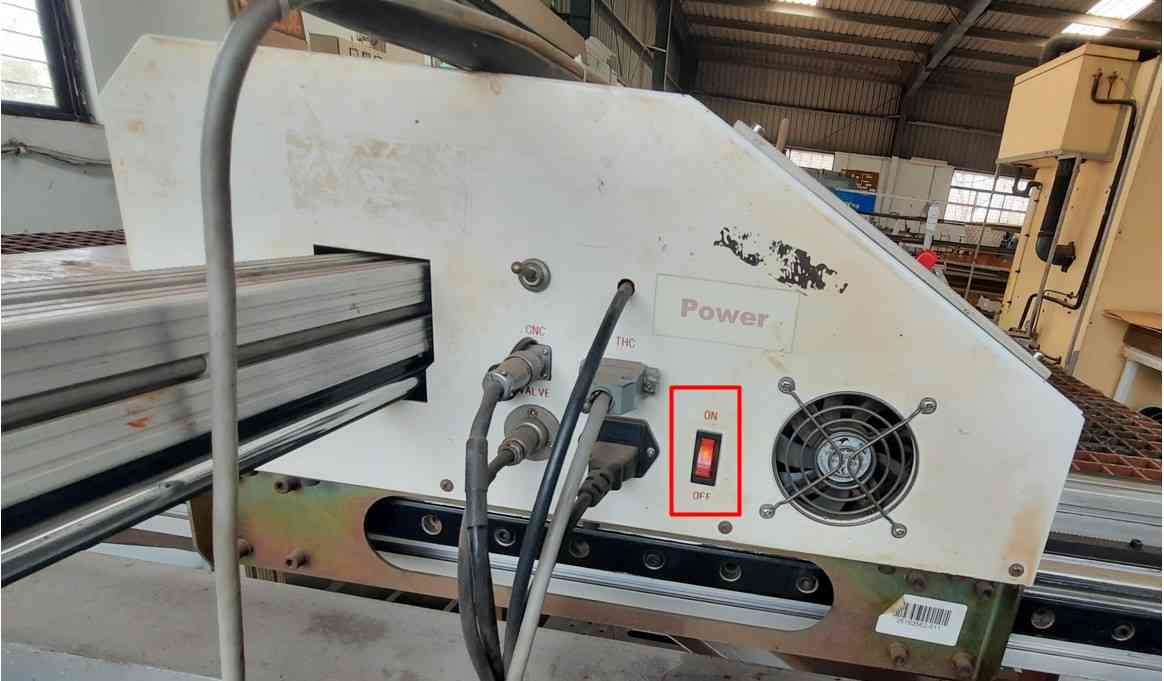
Switch on Control panel.
Sending G-Code to Control Panel.
Following are the steps I follow to load the G-Code file and cut the MS sheet.
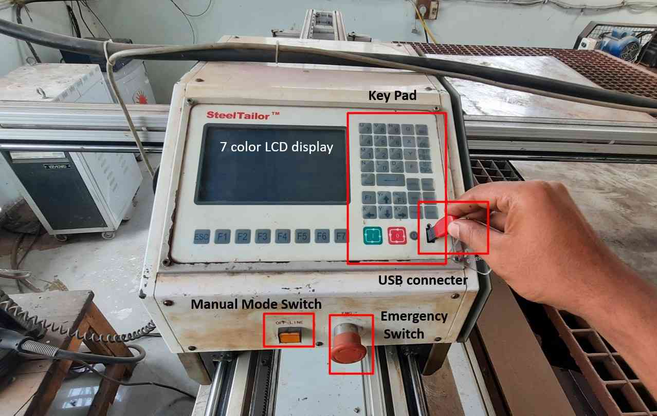
Attach the USB.
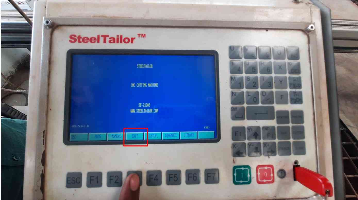
Go to EDIT
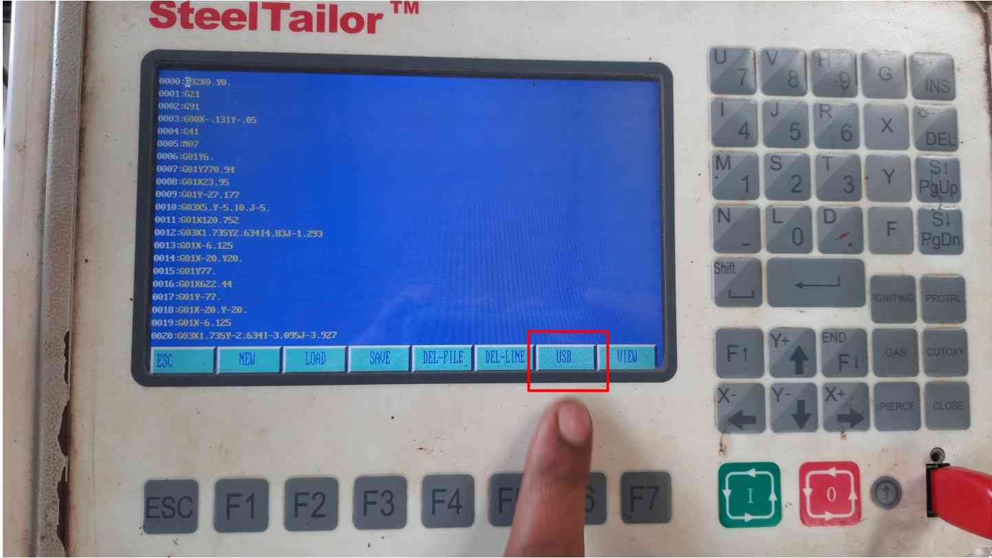
Go to USB.
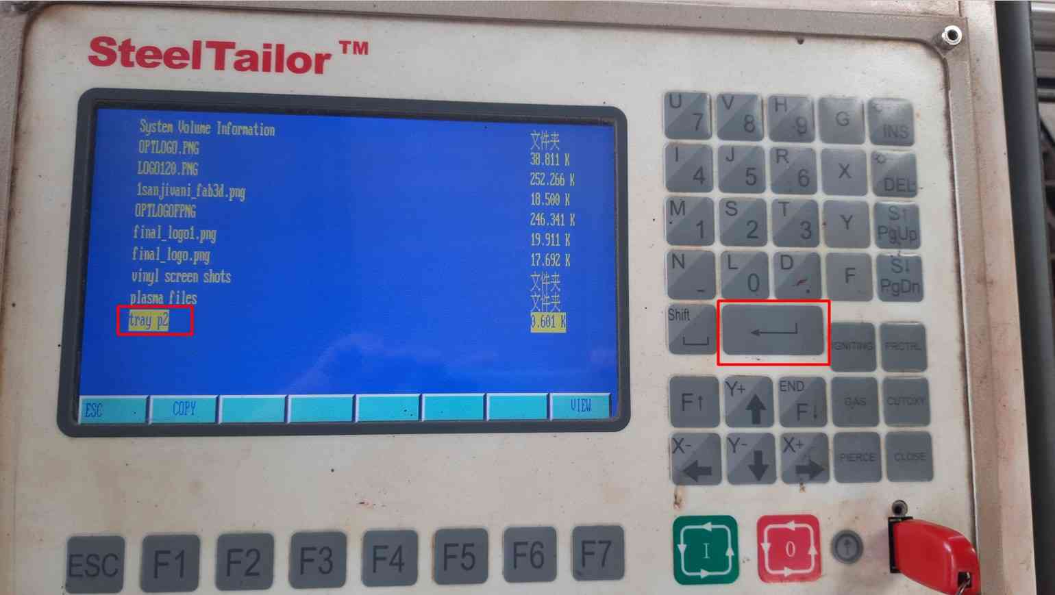
Select the file.
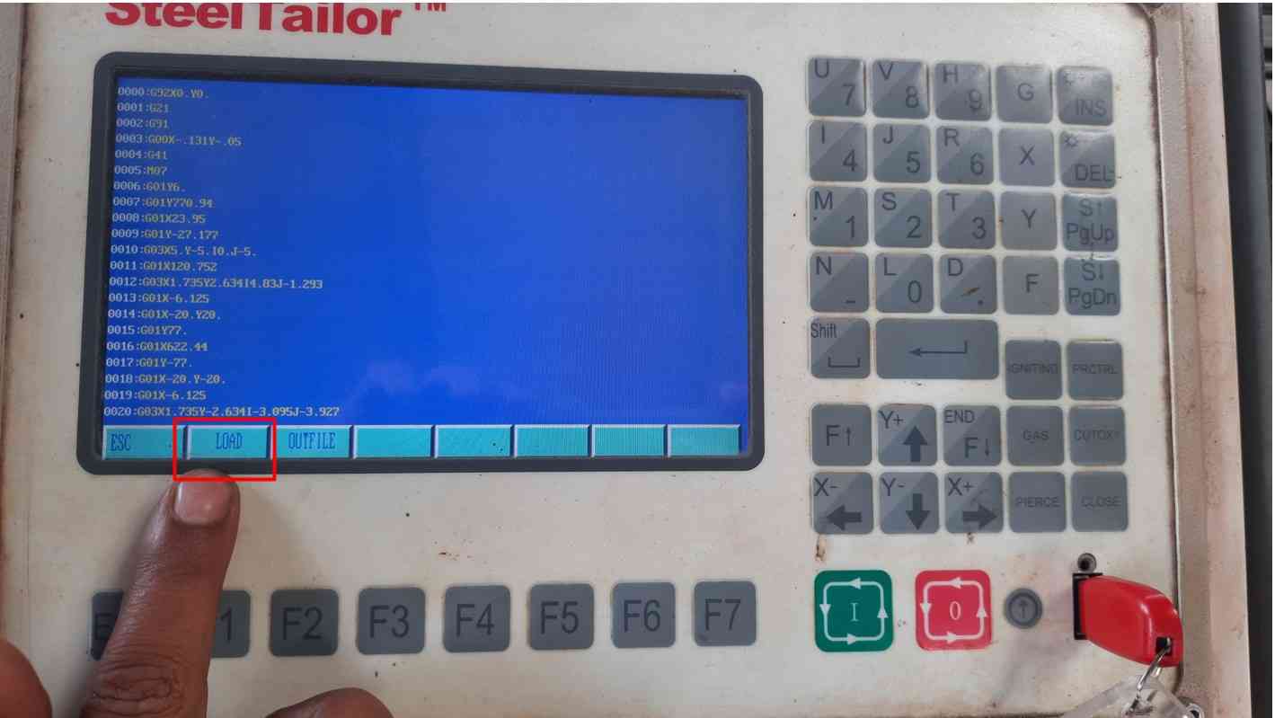
Load the File.
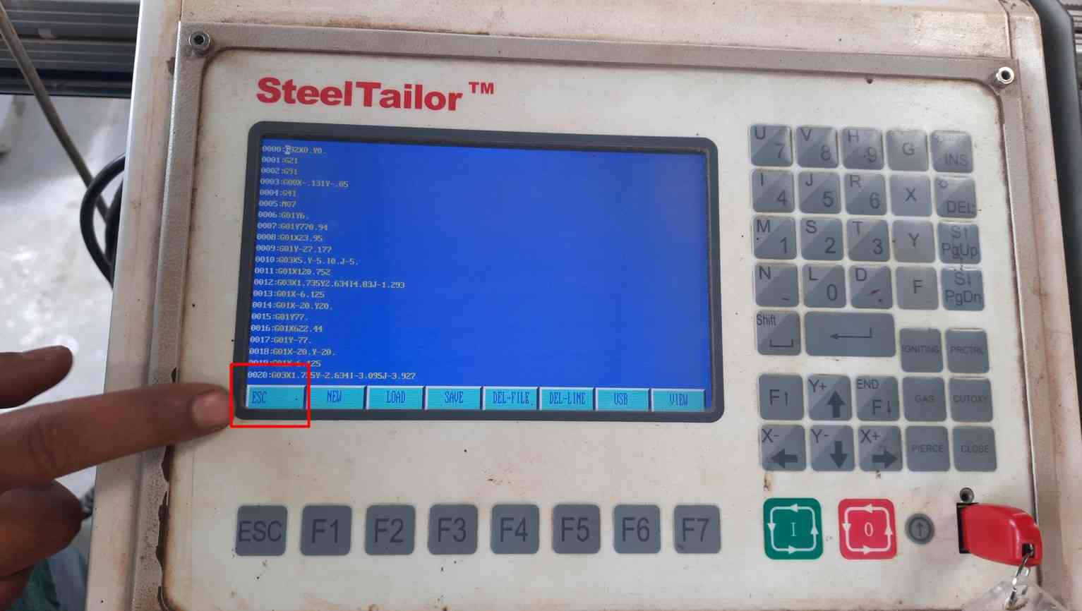
Press ESC to escape the window.
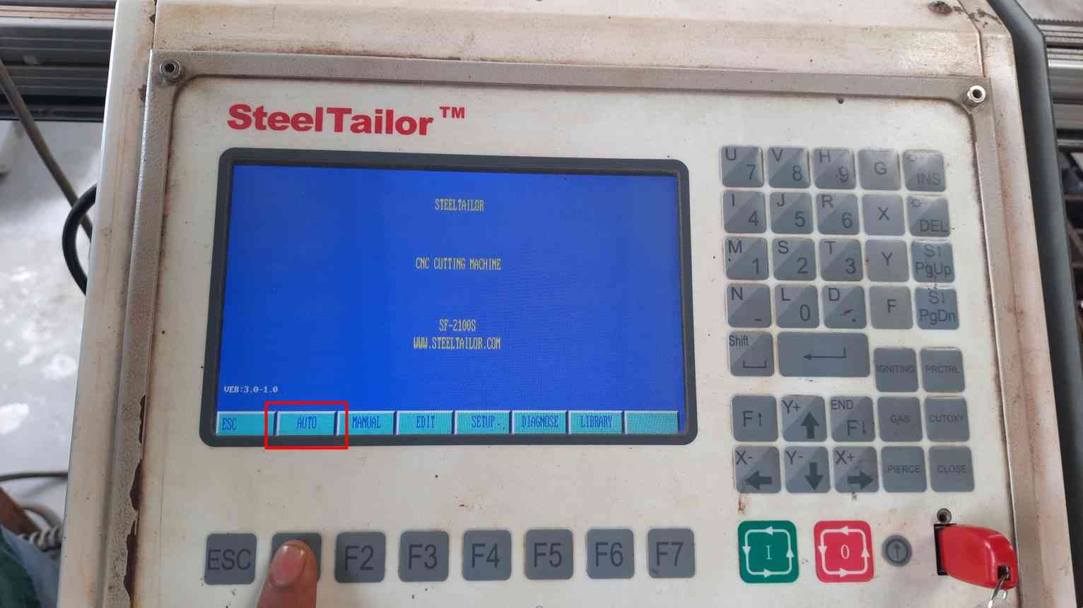
Go to Auto.
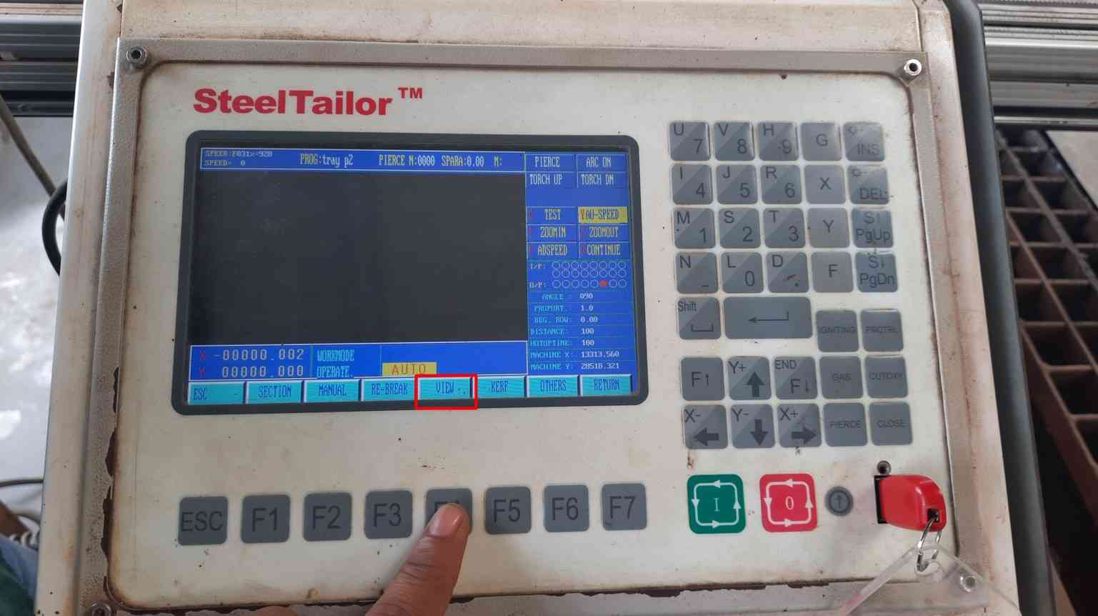
Go to View.
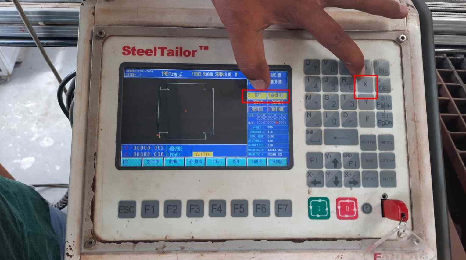
press X to take test run.
In my case I first decided to take the test run.To Ensure the dimension I will require as shown in the following video.
Video of framing the design.
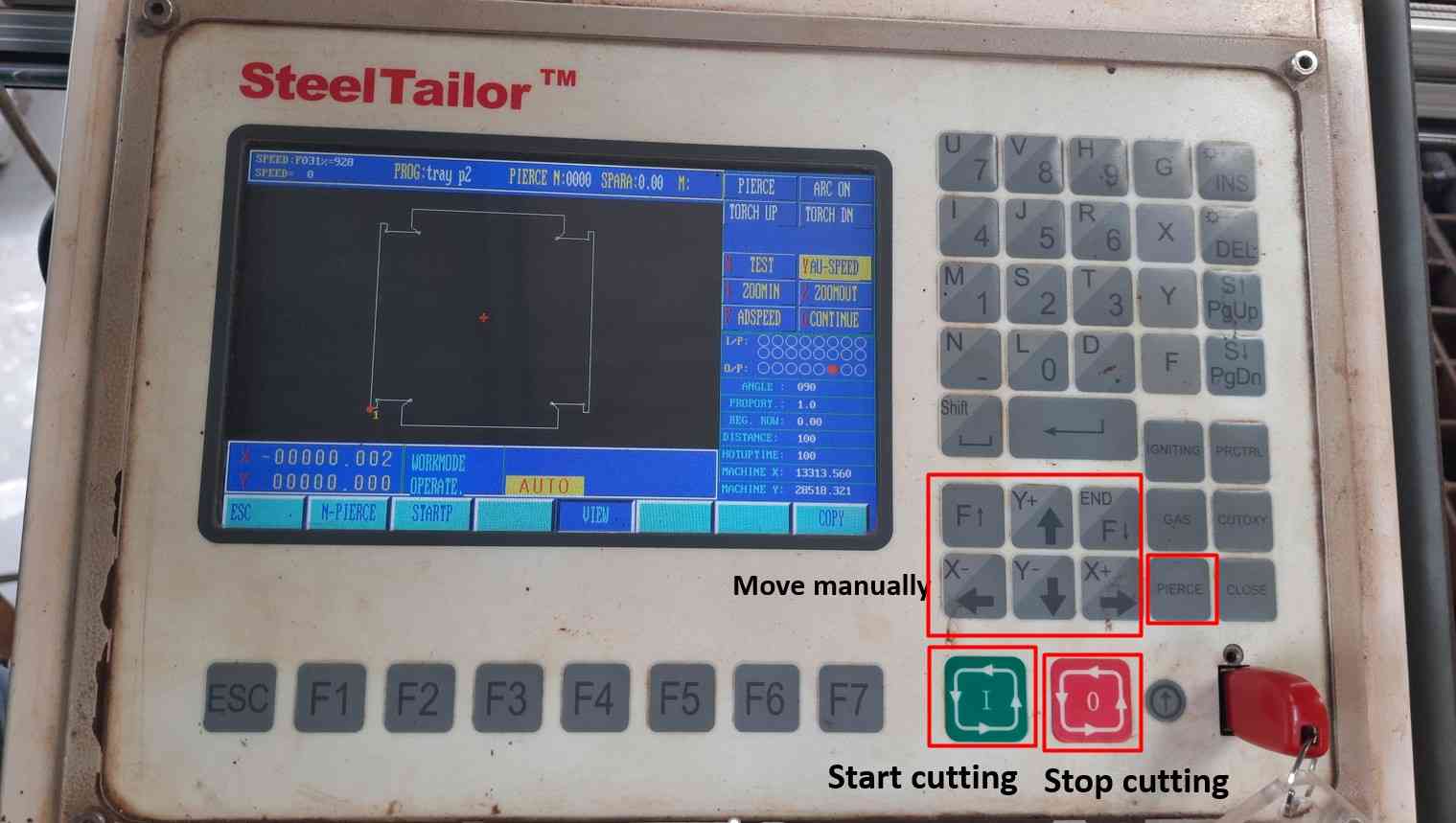
Press X again to move from test mode.
After Conforming to the area required. I Start the Plasma cutting operation by pressing the start button.
Video of cutting the sheet.
Some Additional machining..
After cutting the sheet. It has some metal burr remaining on it. So I have to perform some additional machining such as grinding the sheet and cutting the excess material to make it easy to remove.
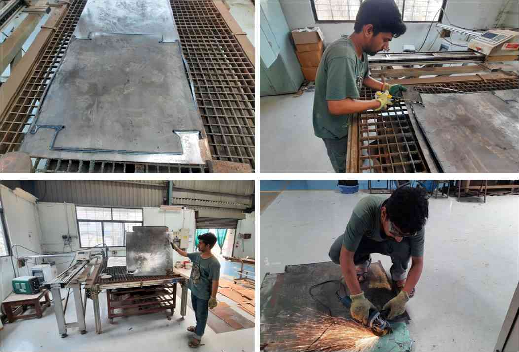
Additional machining processes.
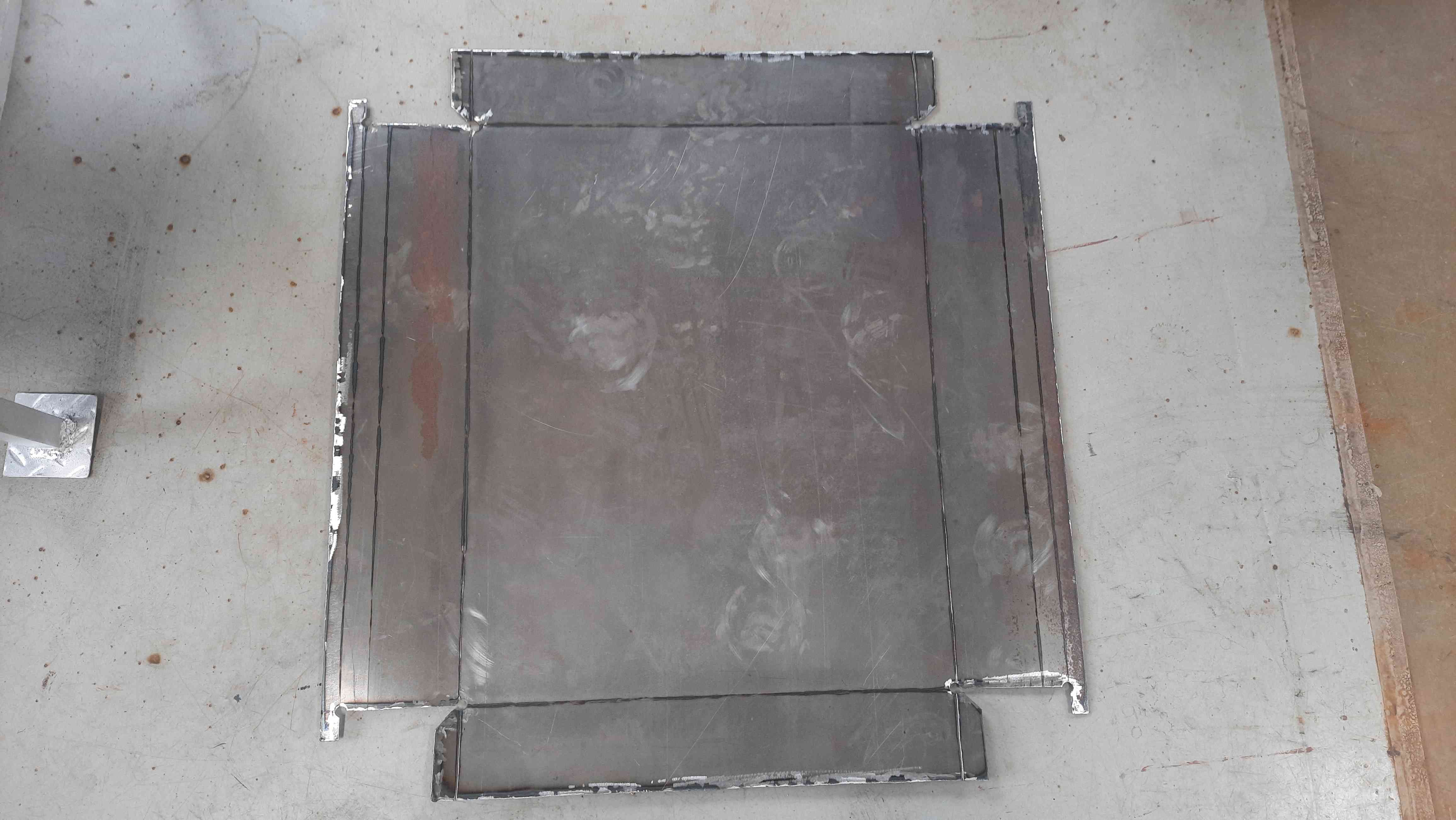
Cutted design after cleaning.
Corner Relief.
I removed some material using a cutter to make the sheet easy to fold. Also the Corner relief and chamfer provided In the design look nice and helpful during folding operation.
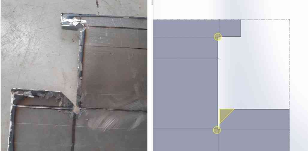
Corner reliefs.
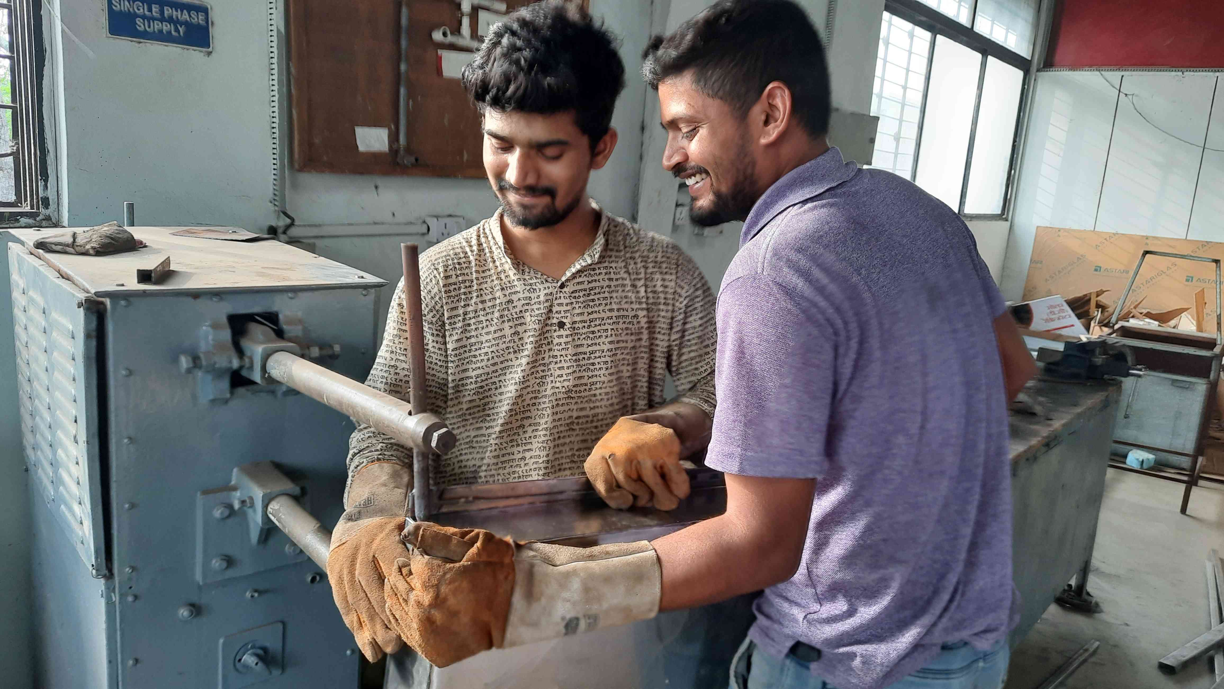
Making the tray .
We have a manual Bending machine at our Workshop.Purnesh help me In bending operation. Some parts of the Ashtray sheet were not easy to bend using the machine So we used to bend it with mallet and Iron blogs to support it.
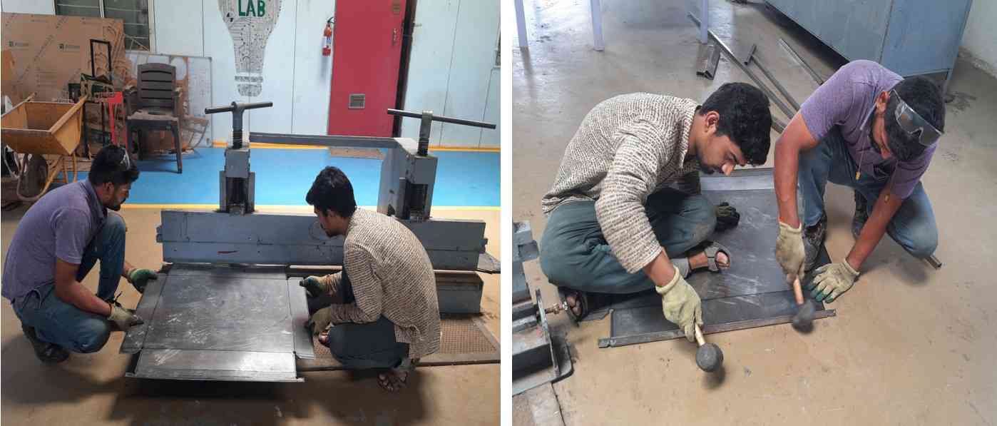
Sheet bending.
To make joins strong We decided to spot weld the edges of the tray. Which we found the easiest and the fastest solution.
Spot welding.
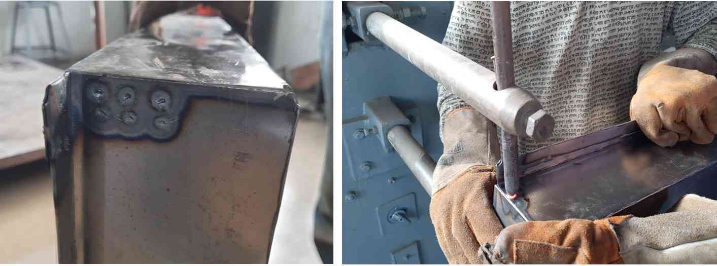
Spot welding.
Video of tray making processes.
Tray making processes.
Hero shorts.
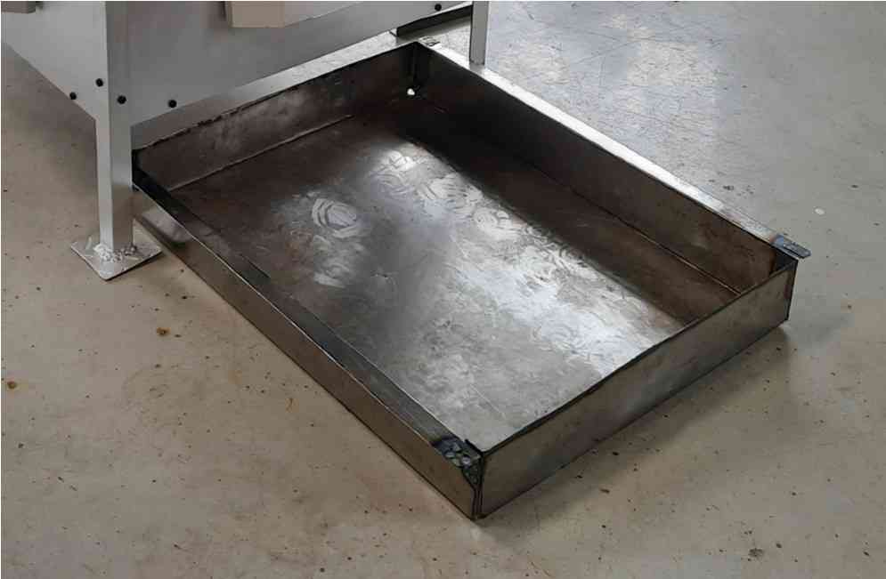
Ashtray.
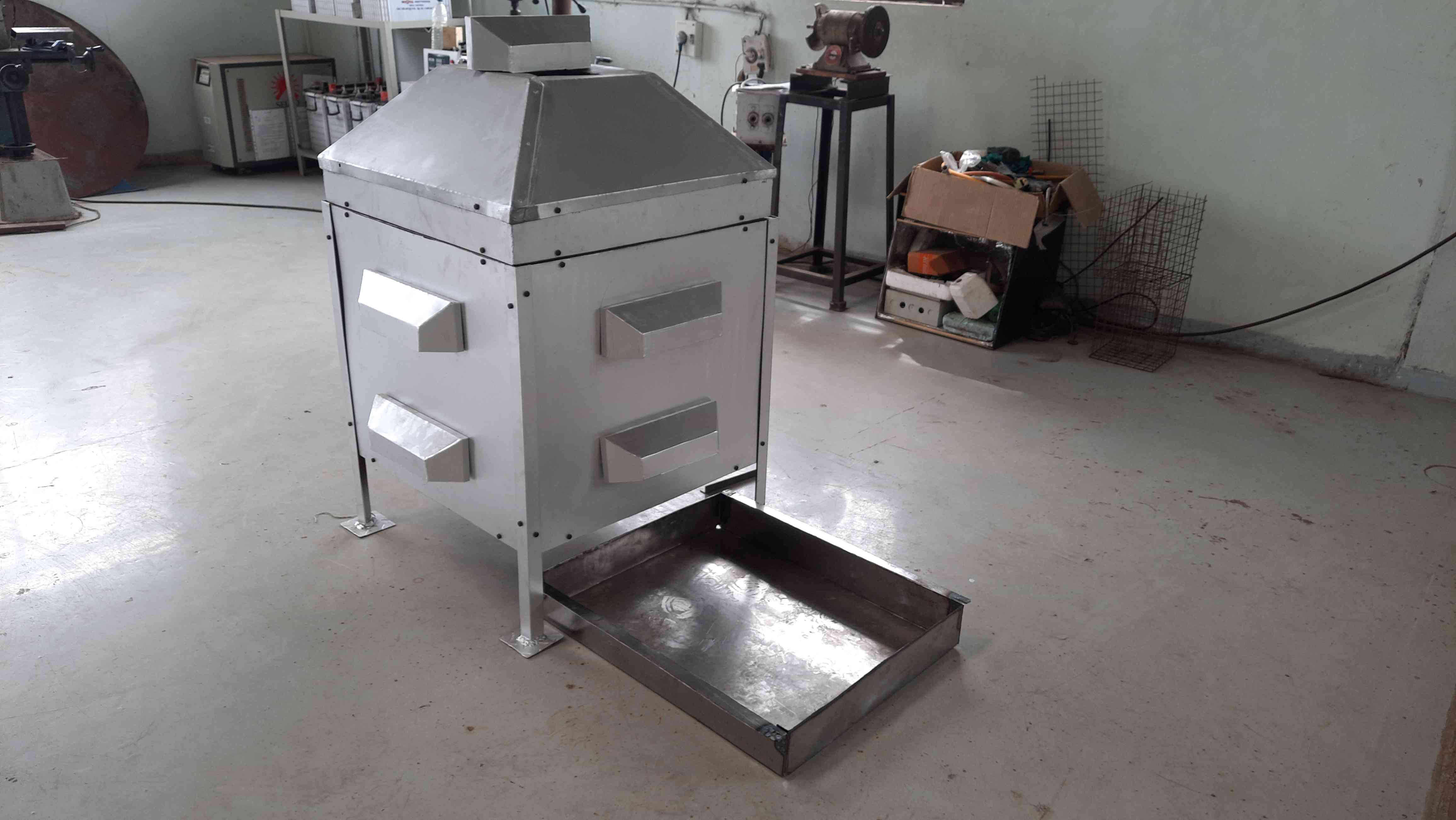
Ashtray with Incinerator body.