WEEK 03: COMPUTER-CONTROLLED CUTTING
GROUP ASSIGNMENT
For this first group assigment, my "fabmates" Esther Pizarro , Jon Merino and myself, had to document the following:
- Laser cutter machine description.
- Safety procedures.
- Caracterization.
- Laser cut focus
- Power
- Speed
- Rate: engraving and cutting
- Kerf: joint clearance, types
1. LASER CUTTER MACHINE DESCRIPTION
Here, on the Fablab.UE Madrid, we not one, but two VLS 6.60 laser cutters:
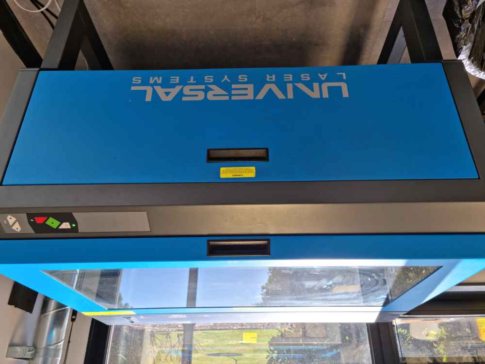
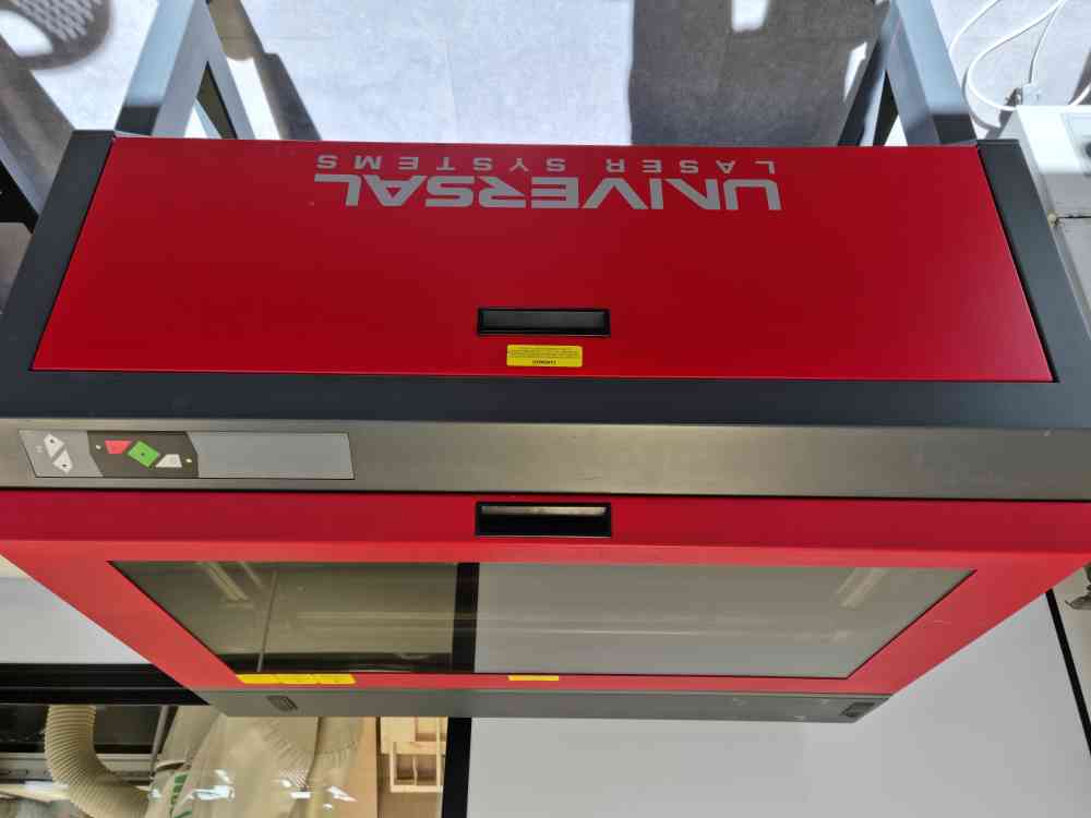
The VersaLaser® (VLS) 6.60 is produced by Universal Laser Systems® (ULS), a company that has been advancing the application of laser technology since 1988, check the ULS history of innovation. It´s a CO2 laser with the following descriptions:
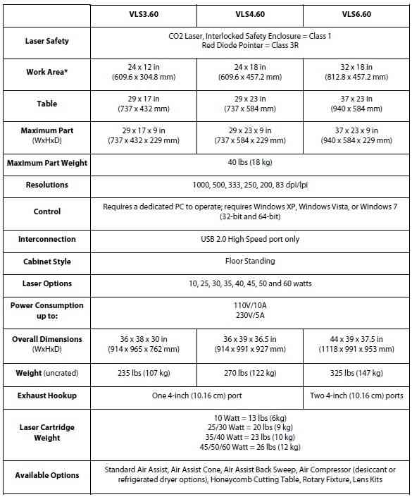
The laser source used in our VLS 6.60 is of 6OW.
2. SAFETY PROCEDURES
This device is designed for laser cutting and engraving, and both need to follow some general requirements to ensure that no damage is done:
- Check that the ventilation is on. A properly operational particulate and fume exhaust is mandatory when operating the laser system.
- Turn on with the lid closed. Exposure to the laser beam can cause severe damage.
- Calibrate and add material.
- Before using a material for the first time, check the material safety data sheet. Some materials can produce toxic and corrosive fumes.
- Never operate the laser system without constant supervision of the cutting and engraving process.
- Never leave materials in the laser systems after the laser processing has finished
- ADMITTED MATERIALS:
- Up to 6mm cardboards.
- Up to 5mm feather board.
- Up to 5mm Metacrilate.
- Up to 5mm Wood.
- Up to 5mm EVA rubber.
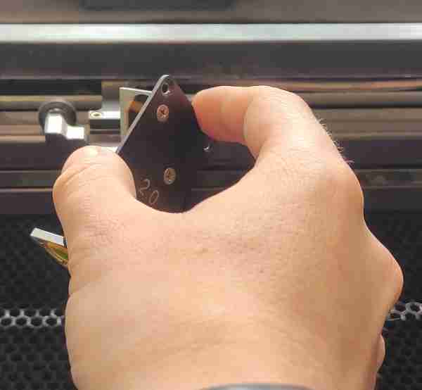
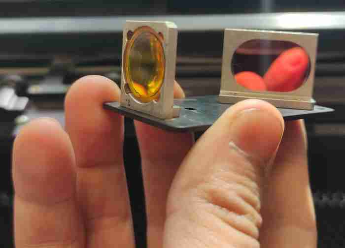
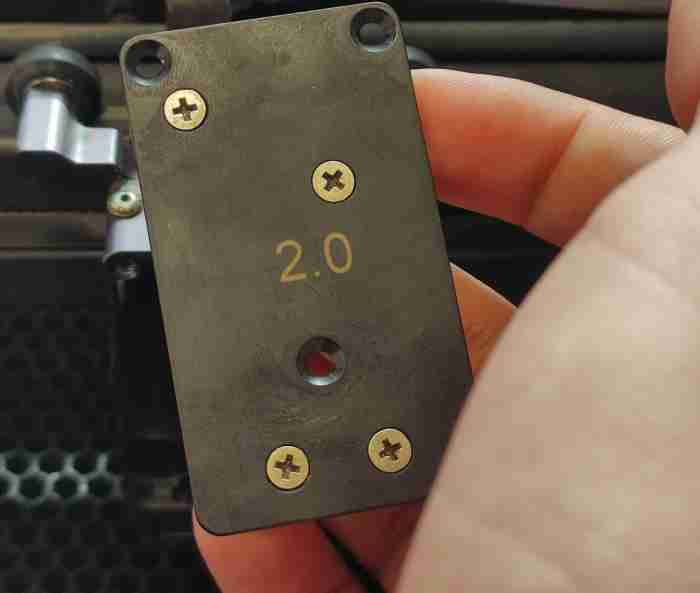
LASER FOCUS:
Our VLS 6.60 comes with a focus lens 2.0 compatible with engraving and cutting. This lens only needs to be calibrated once, with it´s first use, and afterwards you need to maintain it clean in other to ensure optimal functionality.
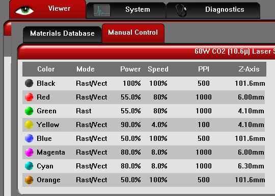
POWER AND SPEED
% Power and % Speed, work together in determining how deep the engraving or cutting will be. Higher power and slower speeds produce deeper results. Lower power and higher speeds produce shallower results. Our FabLab has a library of materials that every user of the FabLab can access, this two parameters, together with the pulsing frequency, or pulses per inch (PPI), can be loaded in the VLS 6.60 printers interface trough a library of materials that our FabLab has prepared for any user, as you can check in our instructor, and FabLab Alumni, Alberto Gonzalez. repository, helping reduce risks and laser cut failures.
LASER PROGRAMING
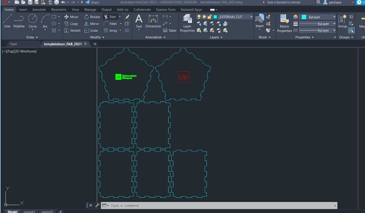
In order to make the laser running and cutting!, we use two different programs, first, we use an autocad laser template from our FabLab, so everybody can use the same library of materials, and afterwards, we load the template in the printer driver interface,in this case, we followed these steps:
Laser programing |
|---|
| Open Autocad and Export your .dwg file and open it in the fablab.UE lasertemplate |
| Adjust your layers and check the size ratio is 1:1. |
| Centre your design, _EXPLODE and _OVERKILL. |
| Make a dot in the upper left corner for the design coordenates. |
| Export your template to the printer driver interface. |
| Adjust your previous layout window, select the full lenght of your template and accept. |
| Open the VLS interface, change coordenates to (0,0). |
| Load your material preconfigured settings from the fablab.UE materials library. |
| Double check that the power, speed, PPI and material density is correct. |
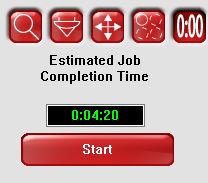
| Load Settings and check that the projected time is reasonable. If not revise settings. |
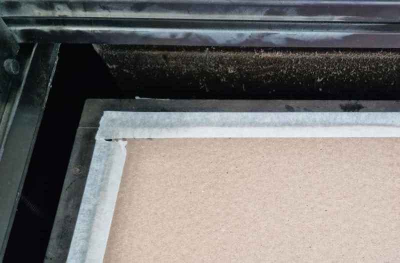
| Prepare your material in the laser cutter. Don´t forget to use masking tape to avoid the material from moving. |
| Start cutting! and rembember to supervise all the process. |
3. CHARACTERIZATION
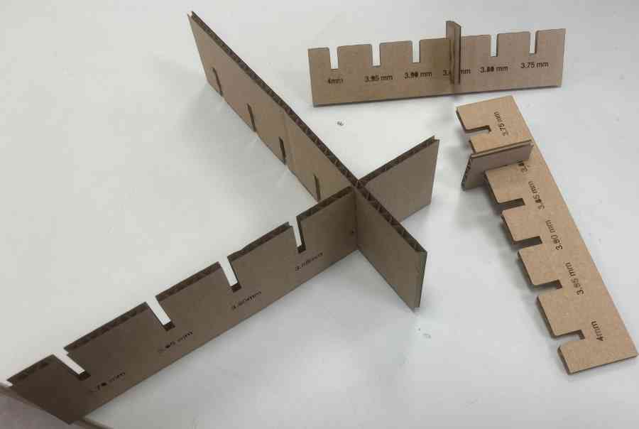
To measure our VLS 6.60 Kerf, we prepared a set of combs, in 6mm cardboard, so we could measure the difference between our original design and the final (laser-cutted) designed. We also, evaluated the optimal pressfit for our individual assesment.
Our initial settings, were as follows:
Power= 80%; Speed= 8%; PPI=1000.
Once we had our design, and program configured, we introduced the material in the laser cutter and fixed it with masking tape to prevent our material from moving while the laser is cutting. When it´s done, we don´t need to hurry to open the safety lid, we let it ventilate to ensure there are no toxic fumes, and now, we open and remove all of our material and masking tape, leaving it as clean as we found it, or even better!
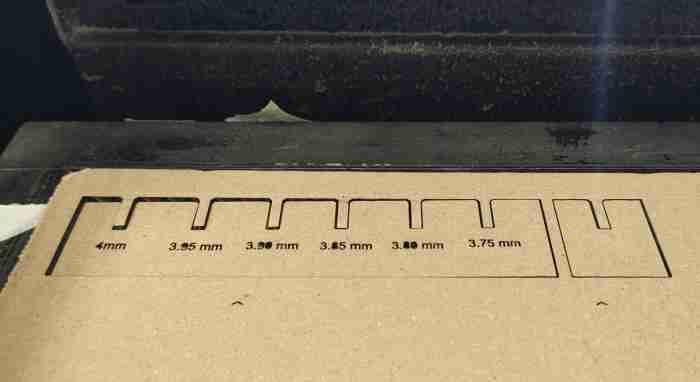
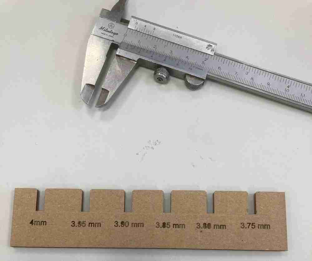
After the measurement, we obtained a final Kerf = 0.30mm in 6mm cardboard.
So now that we know more about our VLS 6.60 lasers, we are ready to begin with the individual laser cutting assigment!
For final thoughts, after my first couple of times, everything went ok, no major issues, but definitely I need more hours to get confident with this machine.. let´s give it more time to see if the spark "ignites" between us..
INDIVIDUAL ASSIGNMENT
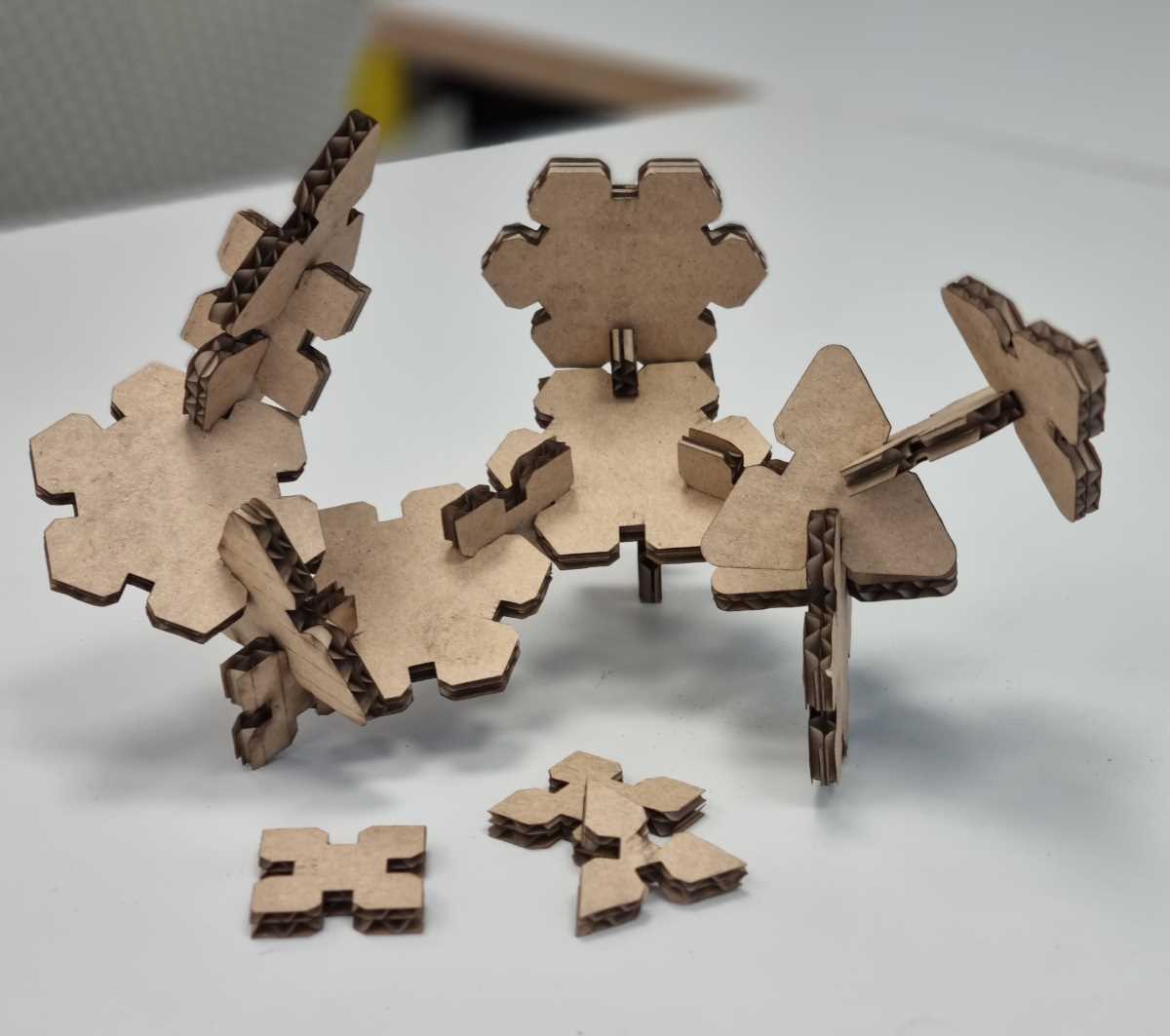
- Design, laser cut, and document a parametric construction kit,accounting for the laser cutter kerf, which can be assembled in multiple ways.
- Cut something on the vinylcutter.
As I start with 0 background on this subject (As usual..), I planned, after the global session, a progressive documentation + practice schedule dividing my first spiral goals as follows:
- Parametric designs for the laser cutter.
- Documentation regarding our FabLab lasercutter´s properties (done on grupal assignment).
- Preparing an image for the vinylcutter, selecting editing program and driver.
- Hands on with safety and tests-cuts practice.
- Vinyl and laser cutting of my final designs.
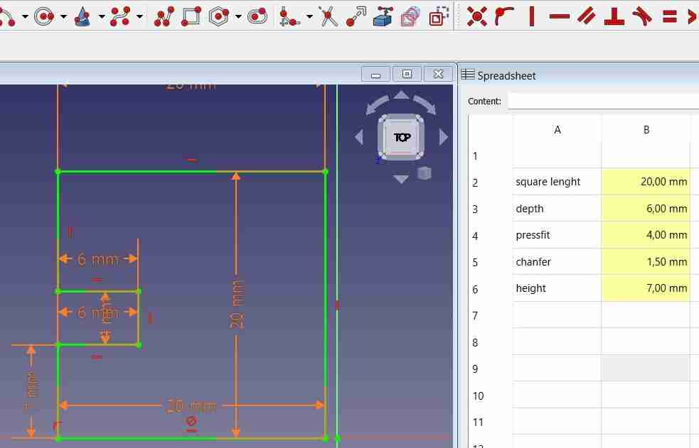
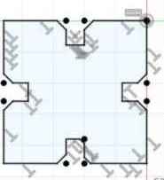
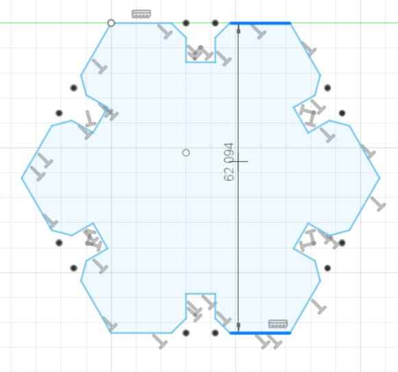
PARAMETRIC DESIGN
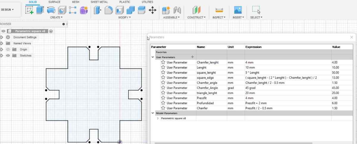
For the next steps on this week´s assignment, i´m going to practice my fisrt parametric design. I´ll use FreeCAD to start with, as I got some hands on experience last week. My goal is going to be to practice some simple designs so I can use them for the cosnstruction kit assignment. So, as I start with 0 background (I´m starting to get repetitive on this!), I found this simple, but yet effective tutorials, of how to go parametrics on FreeCAD from the Fabacademy tutorial videos. After an intense practice, not only with the parametrics, but with the body creation, pad, etc.. I wasn´t comfortable with this program at all, I just kept messing it all up, so sadly (well, not really), I let it go, and started usign Fusion 360, apparently a more "complex" program, but as it´s the program I want to work with during Fab Academy it´s worth taking a try
Suprisingly, after lots of test and errors, a couple of tutorials, and getting inspired with past students repositories fusion 360 tutorial for lasercutting, joemilton, kitija-kumuda, adrian-torres, and patrick-jaruschowitz. I got the hang of it and finally was capable of creating, in a reasonable time, what I had in mind.
Here you can check what issues I had to manage:
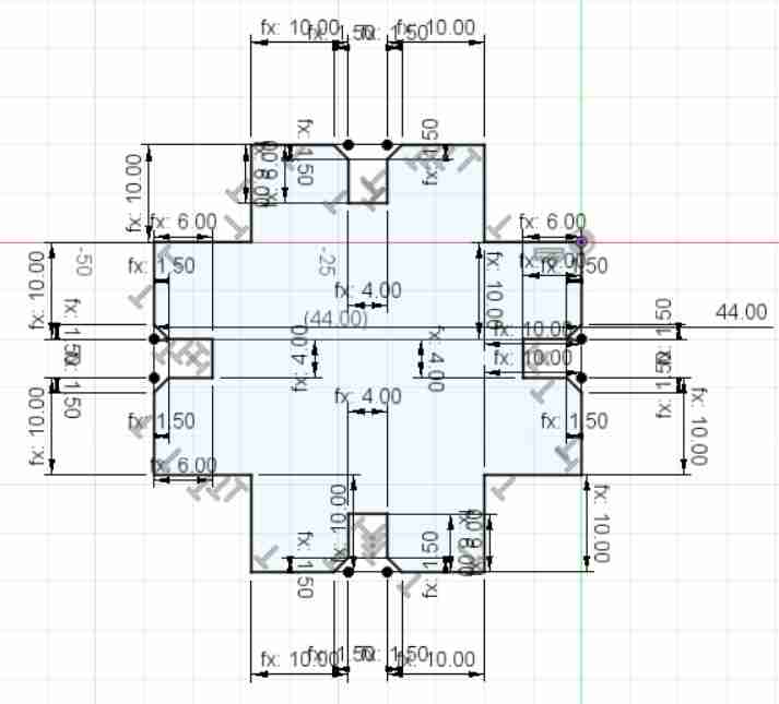
FUSION 360 PARAMETRICS |
|---|
| Define first your parametrics distances: Chamfer, pressfit, depth, lenght, etc.. |
| You can start by creating a pre-defined shape on your sketch, and simply adding simple lines that intersect and model your shape. |
| Get used to using the sketch dimension tool, and make them parametric. |
| Remember to do a smaller design so you can use it as a connector. |
| Export your file as a .dwg so you can open it in the laser template (check grupal assignment). |
As for my final thoughts on parametric designing, I have to admit that, for the third week in a row i´ve had that rollercoaster experience, going very slowly at the begining, how to design in fusion, how all the commands work, make them all parametrics (and make it work!), it can sometimes get very frustrating, but at the end it suddenly everything sums up. I really recommend using fusion 360, at the end it´s quite intuitive and it will be very useful in order to design the final project. As for the designs, In the test cut I made, I figured out I had to make a larger triangle in order to prevent other figures attached to it from colliding.
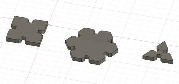
LASERCUT HANDS ON
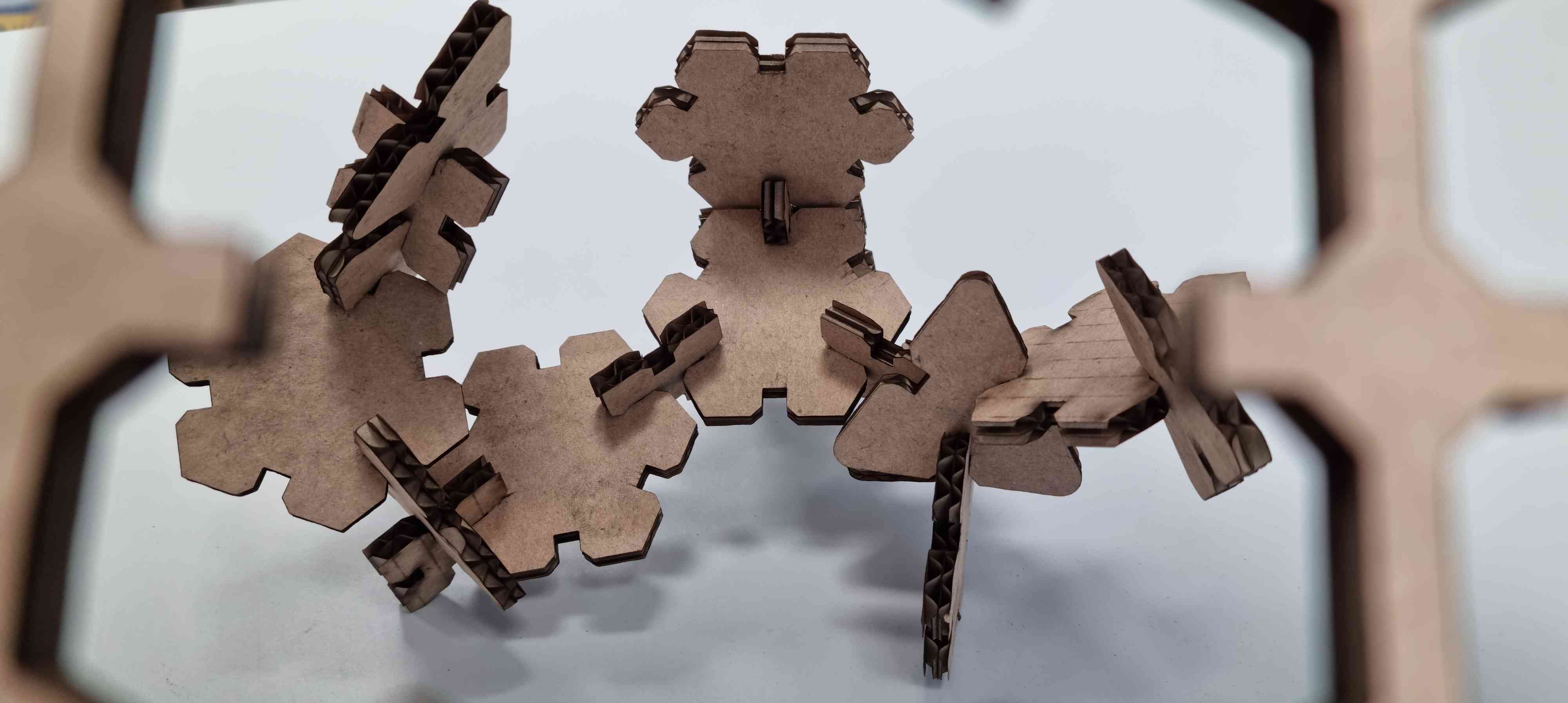
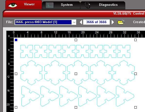
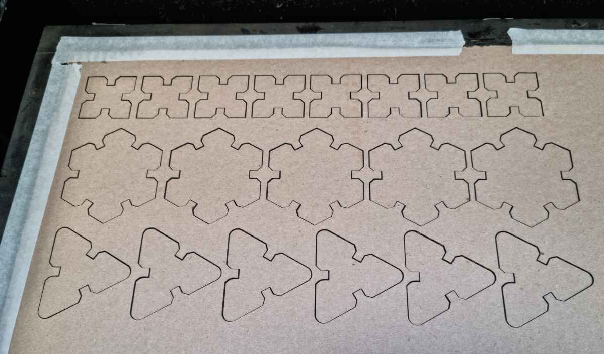
As you can guess from my parametric designs, for my first press fit I´ve decided to create three objects that can be assembled together in different ways, with cardboard.
- Software: .dxf archives managed with Autocad + VLS 6.60 printer driver interface.
- Material: 6mm cardboard.
- Settings: Power: 80%, Speed: 8%. PPI: 1000.
Finally, following the grupal assignment procedures, we obtain our first design cutted with our Laser VLS 6.60!
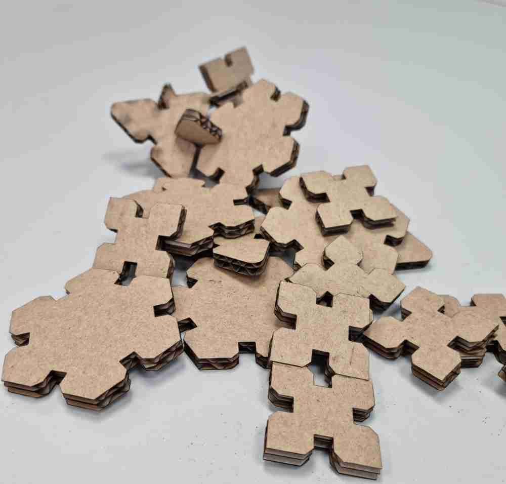
So, in conclusion, i´ve learnt tons these few days. I was a little bit worried because until monday I didn´t have the time to practice with the laser but everything turned out pretty well. I learnt to go parametrics, use autocad lasercut templates, VLS software, printed and laser cutted figures with no issues. As for what could i´ve done better, I would have loved to practice some kerfing but had to manage my time to acomplish with the other assignments. But surely will get to the kerfing sooner or later.
VINYLCUTTER
This week, my planning is conditioned by our family situation, we´re confined until next monday.., so, I have to use my first 4 days to investigate, learn, and document my vinylcutter design firstly, and my laser cutter design secondly. And at the same time, gather information of the lasercutter machines that my FabLab ( FabLab.UE) has, so, when I can start my hands-on on monday, i´ll invest my time in testing and re-testing machine safety, settings and finally producing my assignments.
The good part of this planning is that i´m going to start on the contrary compared to my FabLab colleagues, because they´re going to start (for sure) with the hands on experience, so on monday we´ll all probably benefit of this planning.
Finally, it´s important to add that I´ll work with all the machines on a Windows 11 laptop, just for you to know.
VINYLCUTTER IMAGE DESIGN
To kick off with the vinylcutter images design, I firstly opted to use INKSCAPE, just because I learnt how to use it last week, CAD´s week. So, after choosing my images, I tested how could I convert them from raster to vector with the best outcome possible, so for the you see right below, this was the steps taken to improve it:

VECTOR IMAGE IMPROVEMENT |
|---|
| Trace bitmap. |
| Multiple scans and Brightness cuttoff. |
| Stack and remove background. |
| Adjust image size to real measure. |
| Color to black and 100% of saturation. |
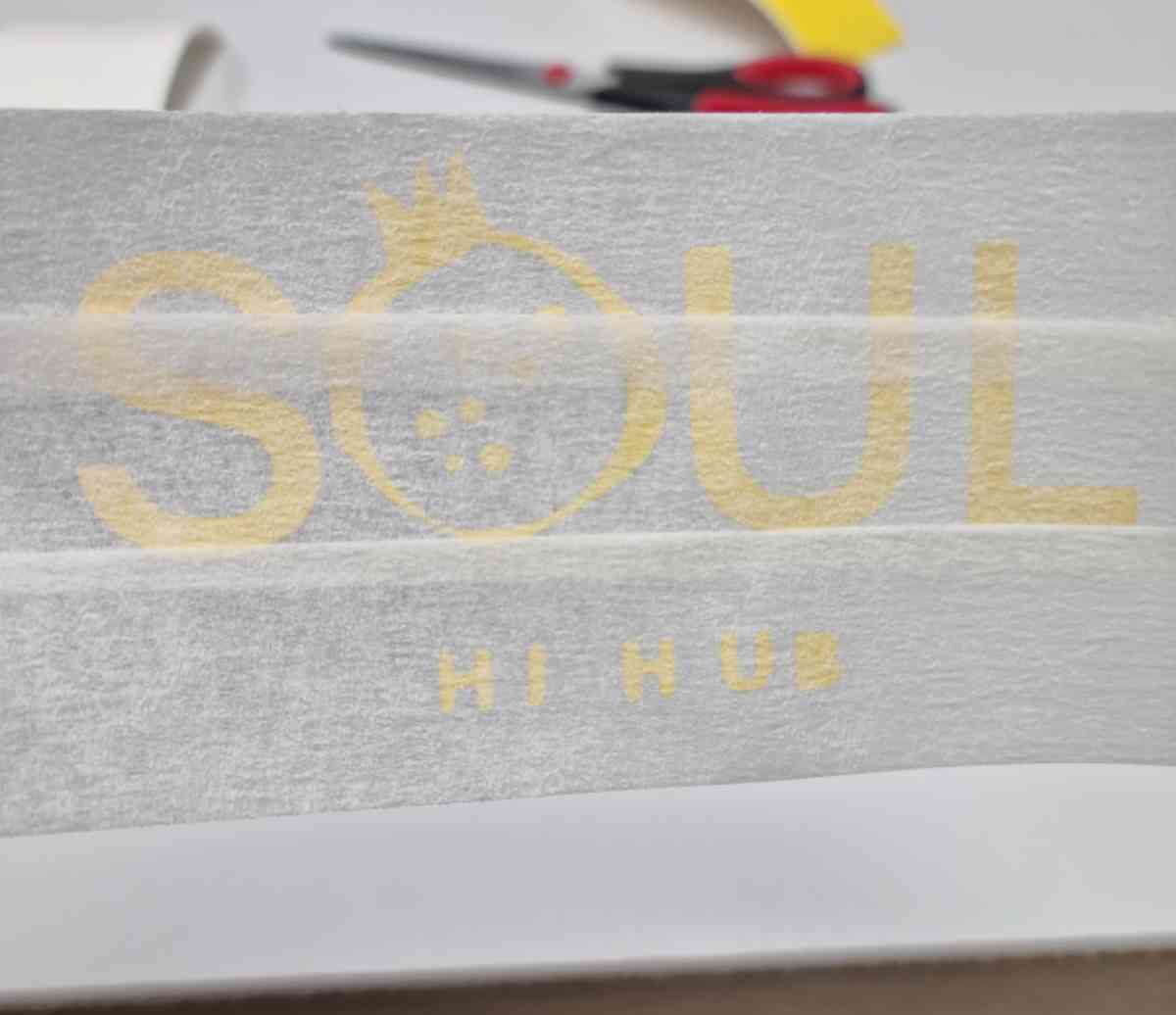
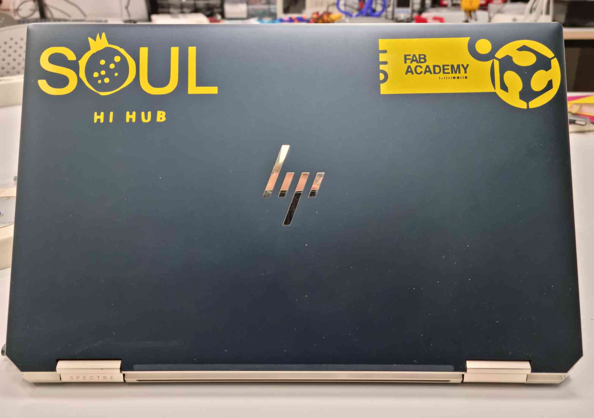
Regarding this image, I personally co-designed this image very recently with other colleagues, as the logo of a Health Innovation Hub we´re actually working on named SOUL Health Innovation. I could resume it as an open community (Social Open University Leadership), with the aim of solving patient-centered healthcare problems, driven by innovation, in a sustainable and collaborative way. So it´s nice to have our own laptop sticker!
Here you have the final images I prepared to practice with the vinylcutter:
VINYLCUTTER HANDS ON
Once all images were converted to .svg files, I followed the steps following Alberto González recomendations in his repository. It suited me well because it´s the same vinylcutter, specifically: ROLAND GS-24 VINYLCUTTER
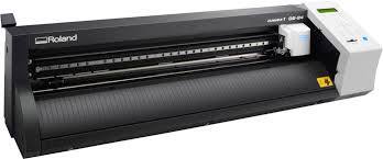
- Software: Roland CutStudio Plug-in for Adobe®Illustrator®
- Maximum cutting area: Width: 584 mm (22.9 in.) and Length: 25 m (984 in.)
- Cutting speed: From 10 - 500 mm/sec (4 in to 19.69 in/s) (all directions)
- Blade force: From 30 - 350 gf
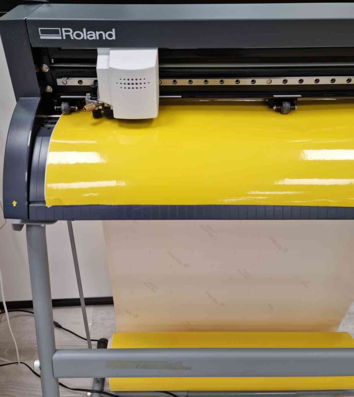
- Load the roll from behind, with the visible part upwards.
- Check the width roll of the machine and replace it on the printer settings if it´s not coincident with the illustrator´s artboard: Printer settings -> preferences-> size-> change the size as the same as the artboard.
- Check there´s no stoke width.
- Check the wheels are lifted, align the vynil from front and rear, lower the wheels and check they´re centered.
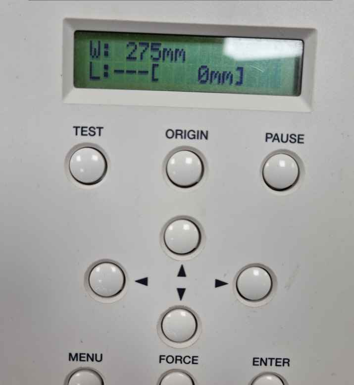
- The machine will then "read" the weel positions and will measure the width.
- Set the cutting speed and knife pressure to 130 grams.
- Do an initial test-cut.
- Open image in Adobe®Illustrator®,Check that the size of the image is CORRECT,check your image is on the lower left corner of the artboard, duplicate as many times you want the image to be cutted.
- Double check by opening the printer settings that the image is well placed and the width of the printer and artboard are coincident.
- ..PRINT!
- Peel off the part you don´t want: Use a masking tape to help with the transfer.
- Before removing the masking tape: We have to be sure it´s correctly attached to the selected surface.
- Shear and don´t tear!
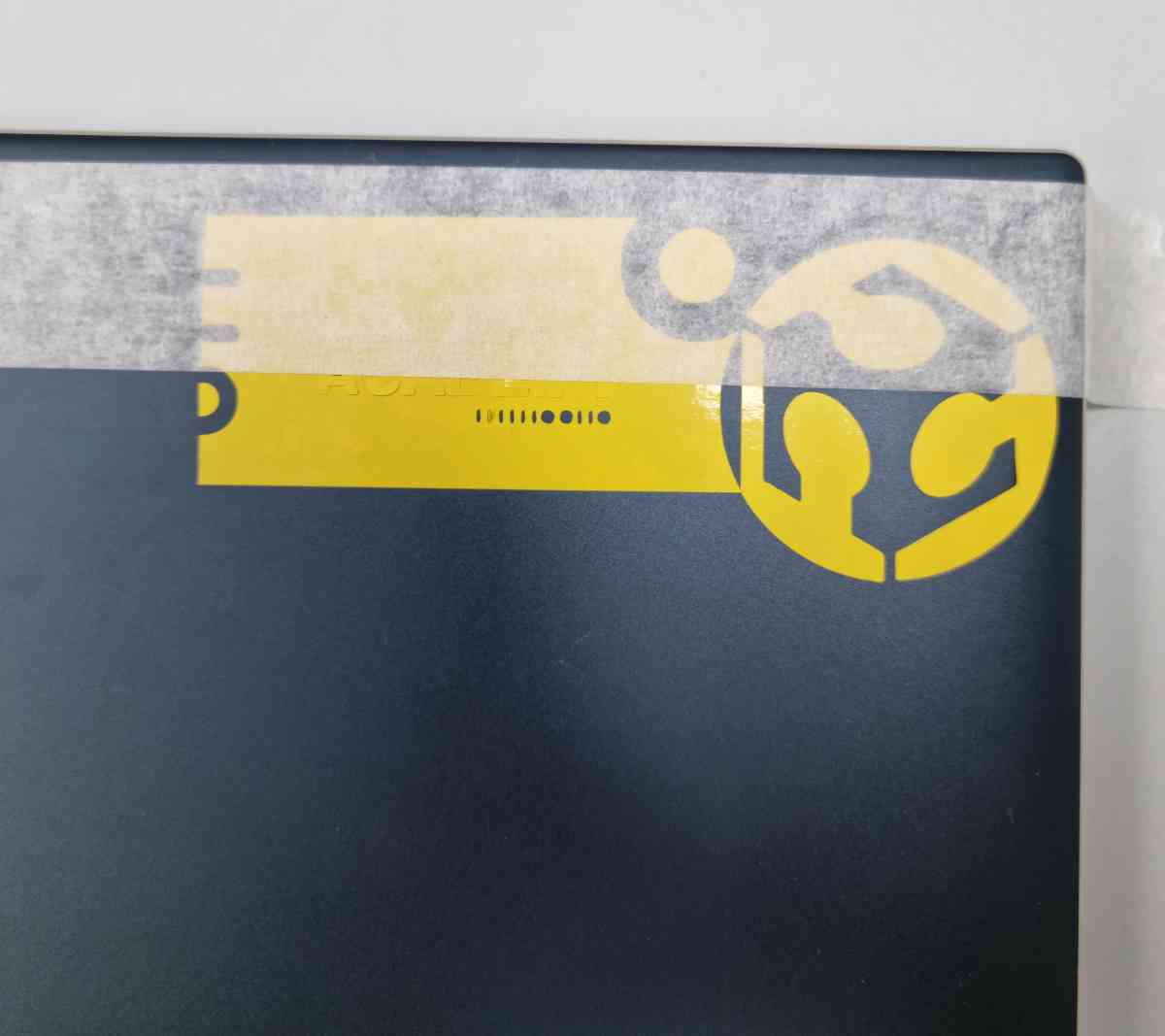
Well, for my final thoughts in vinyl cutting, I really enjoyed it, it was probably the less demanding of all the assignments, but.. the shearing part gave me headaches!. As you can see in my fabacademy adapted logo design, It was a little bit smaller than expected, so the letters where microscopic. But, fortunately, and against all odds (even my fabmates bet against me..) I managed to get all the tiny little details where they should be! And again I ran out of time to try and do some different as textyle vinyl. There´s so many things to practice so little time..
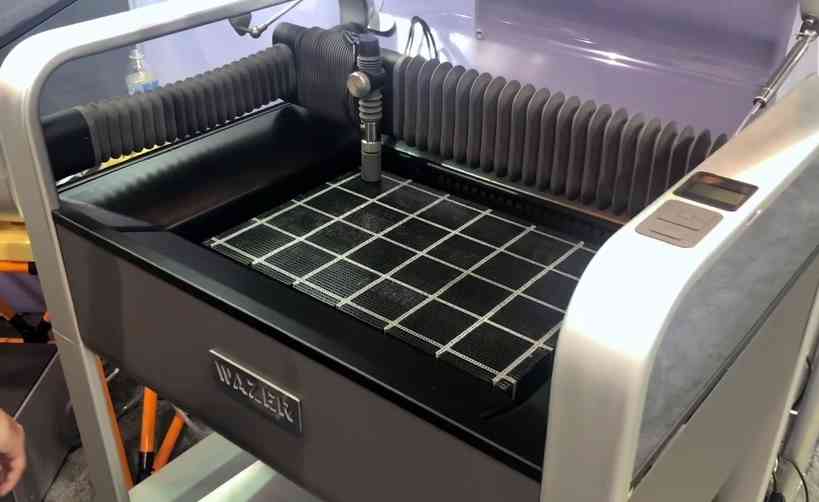
EXTRA BONUS: WAZER
At the final days, we had the opportunity to practice and cut with the Wazer, a desktop waterjet cutter!
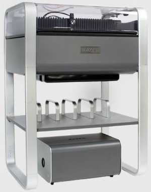
Here you can have a quick glance to its capabilities, but you can access the full documentation in my fabmate Jon Merino grupal assignment.
Materials to be used |
|---|
| Stainless steel. |
| Marble. |
| Boro glass. |
| Carbon fiber. |
| Silicone. |
| High density polyethylene (HDPE). |
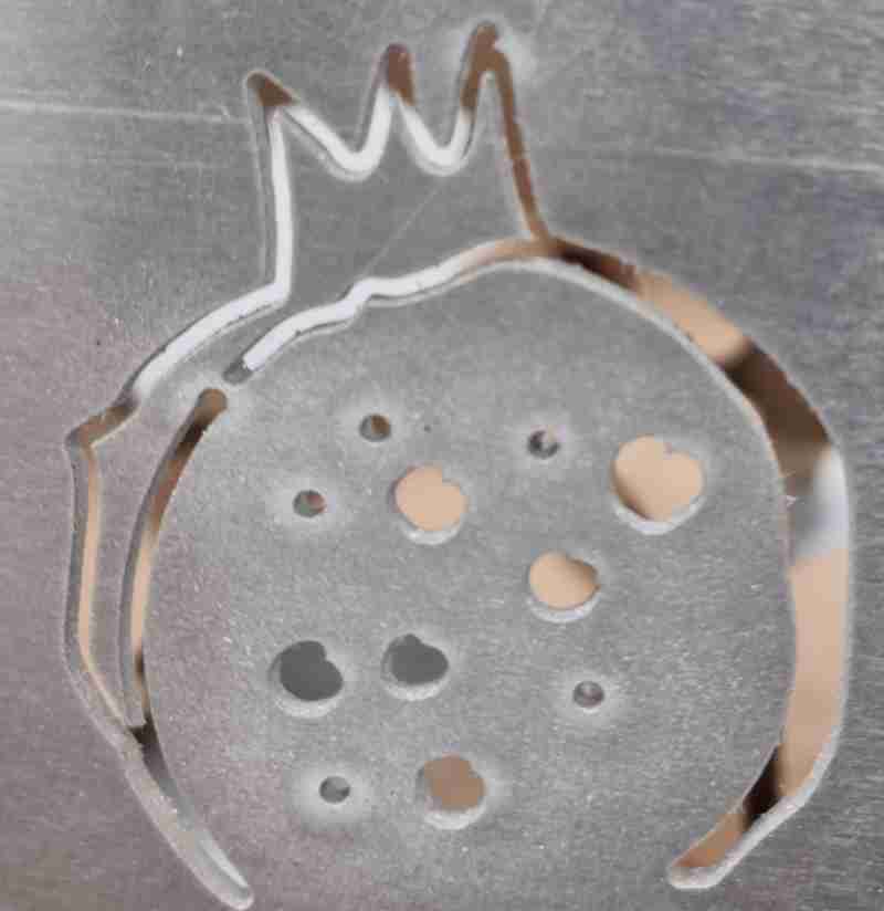
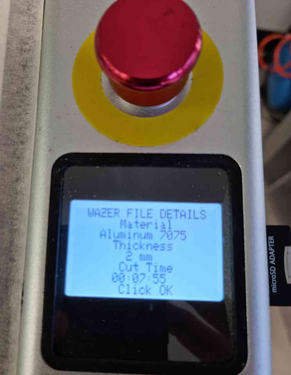
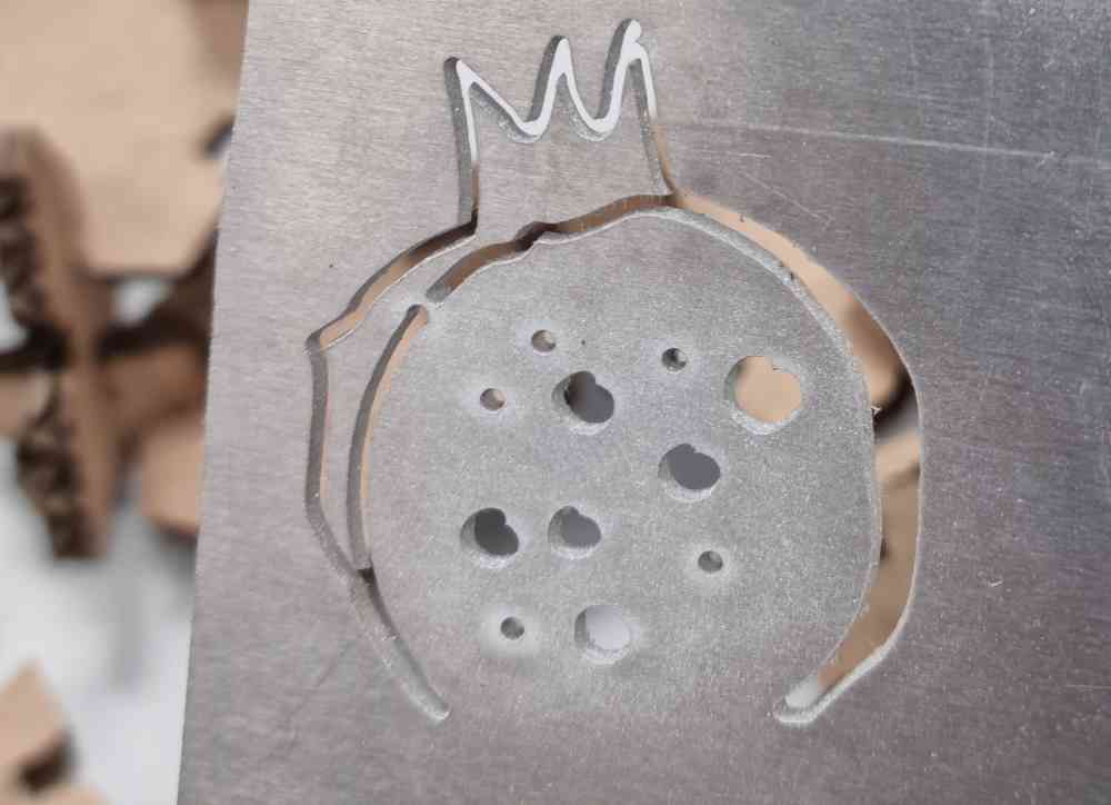
For our fist experience we used 2mm stainless steel. The machine is incredibly simple to use, you can divide the process in two steps, First, to load the file you want to cut, and second after loading the file, prepare the machine for cutting:
FILE DESIGN
Regarding the file design, it´s incredibly easy to use. You can use in the Wazer either .dxf or .svg files, in our case we used one of the .svg files used for the vinyl cutter. As I mentioned before, it´s very simple, you just have to login to your wazer account and follow a very easy and intuitive setting process divided in 6 steps:
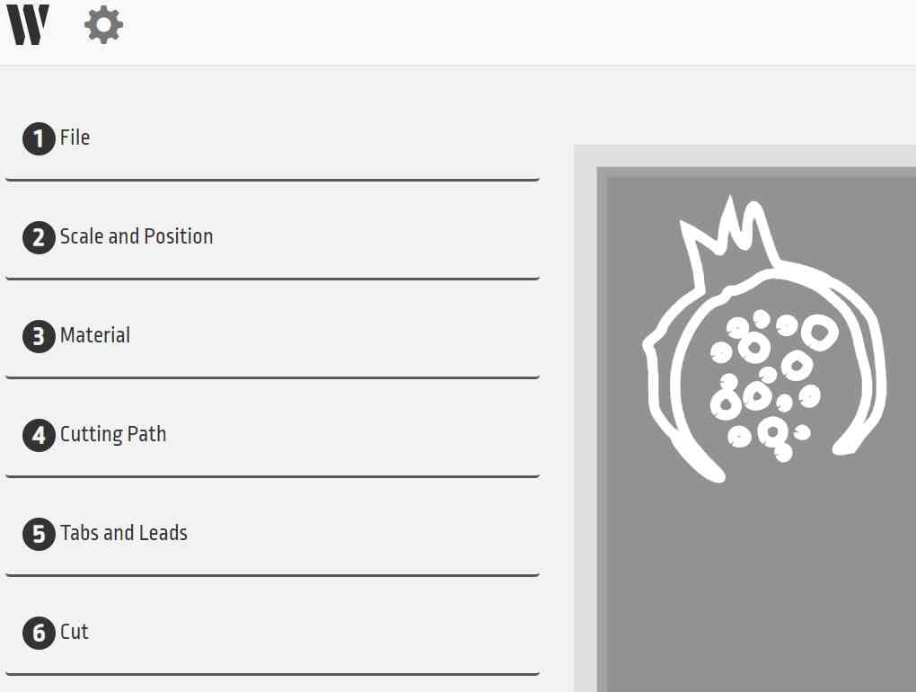
| Scale your design. |
| Select the material Type and width |
| Select cutting path and offset. |
| Tabs and leads: Automatic, manual o no tabs |
| Cut quality. |
| And finally you just have to save the file automatically in a .gcode extension and export it to a SD card, because it´s how you´re going to communicate with the waterjet cutter later. |
WATERJET PREPARATION FOR CUTTING
Now that we´ve prepared our file, we just have to insert the SD card in the machine and follow the programs quick checklist. For this first experience we had to put on gloves and dismount twice the machine.. so we can say we had a full inmersive experience, but all that is already documented in my fabmate assignment referred above (have a look..!).
The steps taken before preparing your first cut are:
- Check that the water level and that the water is on.
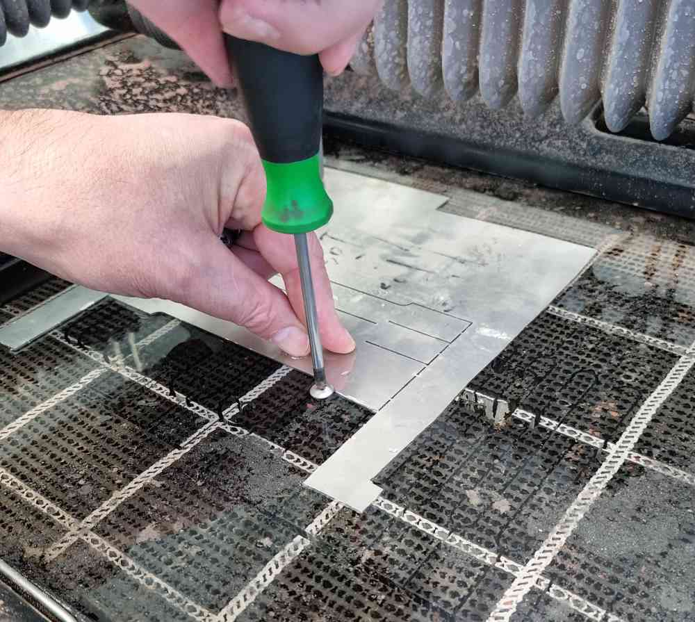
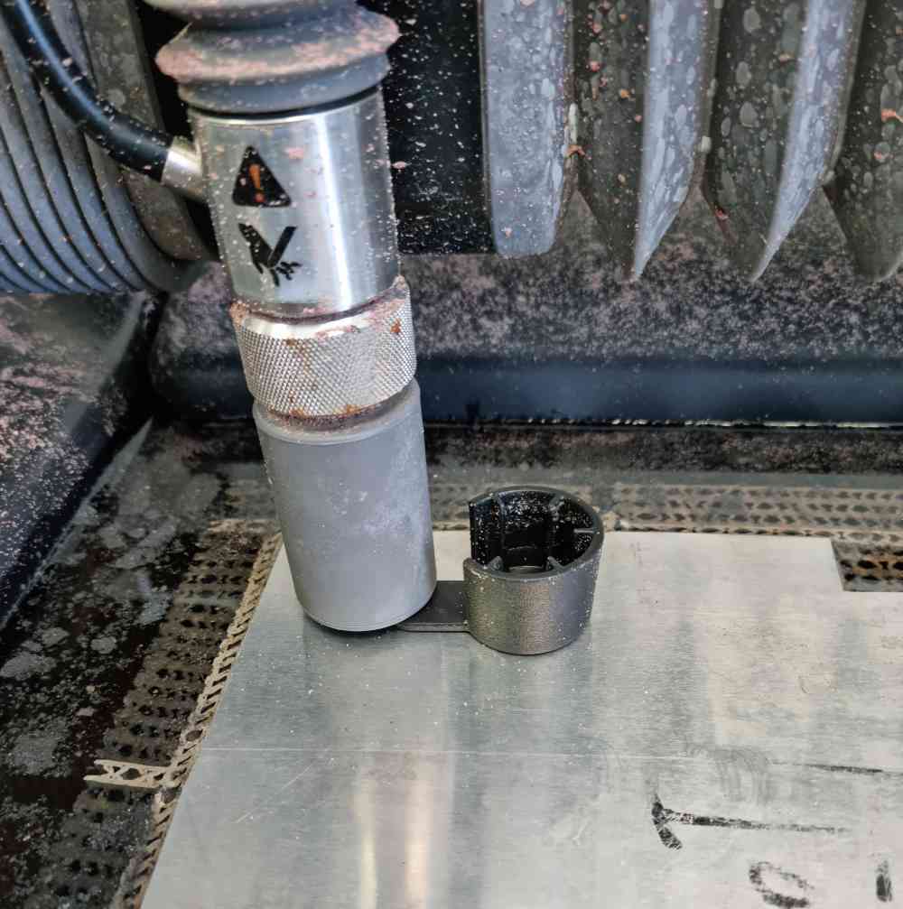
- Adjust noozles height with the noozles height tool.
- Fix the material with screws.
- Load your file and follow the panel instructions.
- Check the amount of abbrasive you´re going to need. The program tells you exactly how much its going to consume.
- You can run a check-cut to confirm the size and also check the cutting time.
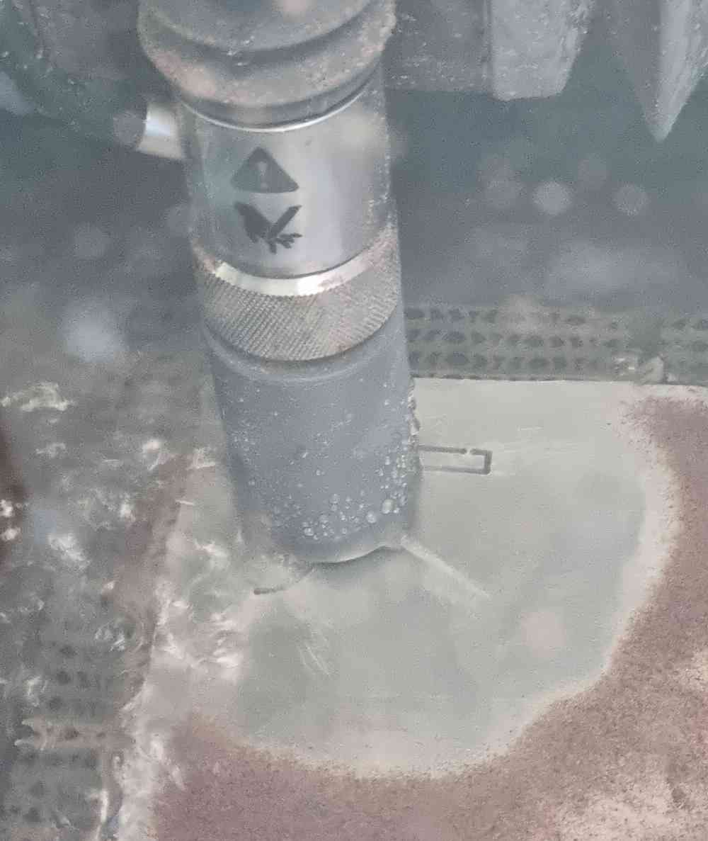
- If everything is OK, you can start cutting.
- Very important: You have to permanently supervise the cutting process and be prepared to pause the machine at any moment. In our case we had to stop it twice because some detached parts could collide with the noozle.
- IMPORTANT: if you stop the machine, do not open inmediately, let the water stop running and let the noozle stops fist.
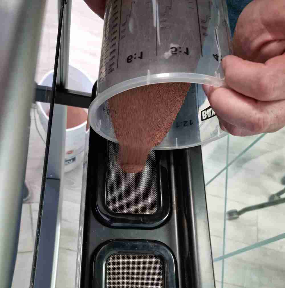
For the final thoughts in our first full inmersive experience with the Wazer is that, first of all is a very dirty machine, you get abrassive product everywhere and it demands constant cleaning. Other negative point is that it consumes a lot of abrassive material, just as an example 7 x 7 cm design needed more than a kilogram of abrassive.. Other aspect to improve is that as it works with water, it leaks constantly and you have to clean filters and check tubes permanently. But on the other hand, it´s very very simple to add a file, and its very simple to set and prepare for cutting because it has a intuitive checklist that pop-outs in the main program that it alerts you were the problems is and what to do to solve it.And most important and best aspect of all, you can cut materials that you wouldn´t be able with other machines.
Back to top