5. Electronics Production
Group Assignment
Characterize the design rules for your PCB production process
Assignment
Make an in-circuit programmer by milling and stuffing the PCB, test it, then optionally try other PCB processes
Prior knowledge
Before this week’s assignment, my knowledge in electronics and soldering was limited to repairing some analog guitar effects circuits and trying to turn on LEDs, some work done in the laboratory (but always assisted) and … misusing a soldering iron to cut some fabric to build a parachute model (yep … everyone has as much fun as they can).
After performing this week’s assignment … I found out what an SMD component is, learned how to mill a copper plate with a 2x1mt cnc cutter … and I look a lot more like Mr. Magoo
What’s a FabISP??!
Everything you need to know about what is a FabISP and how you’ll do it can be found at this page.
Milling
I decided to use the design of Ali I found on the Fab Academy page. It uses the ATtiny44 microprocessor and seemed one of the easiest to weld.
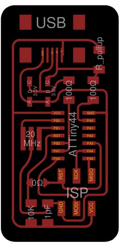
To generate the G-Code to be sent to the milling machine we used Fab Modules, a kind of suite that allows you to set a particular machine (milling, laser, vinyl cutter, …) seconds of the parameters optimized for that specific process.
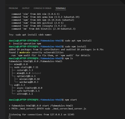
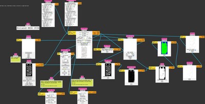
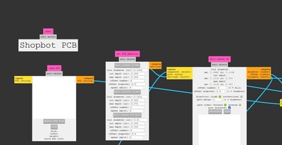
I prepared the files with Fab Modules for the Roland MDX-40A milling machine that we can found inside OpenDot Fablab and…surprise surprise! The Pc used to control the machine wasn’t there. So we decided to switch to the other CNC milling machine, the ShopBot.


But we did an error mounting the Roland MDX stand on the ShopBot worktable without considering that the MDX worktable had been calibrated with Roland and therefore would not have been right for the other machine.

Eventually, after some trial and error to fix the calibration, we started milling.

First I started with the traces with a 1/64 endmill. That worked out pretty well, the calibration of the bit was made on sight so there’re some differencies between the different PCB.
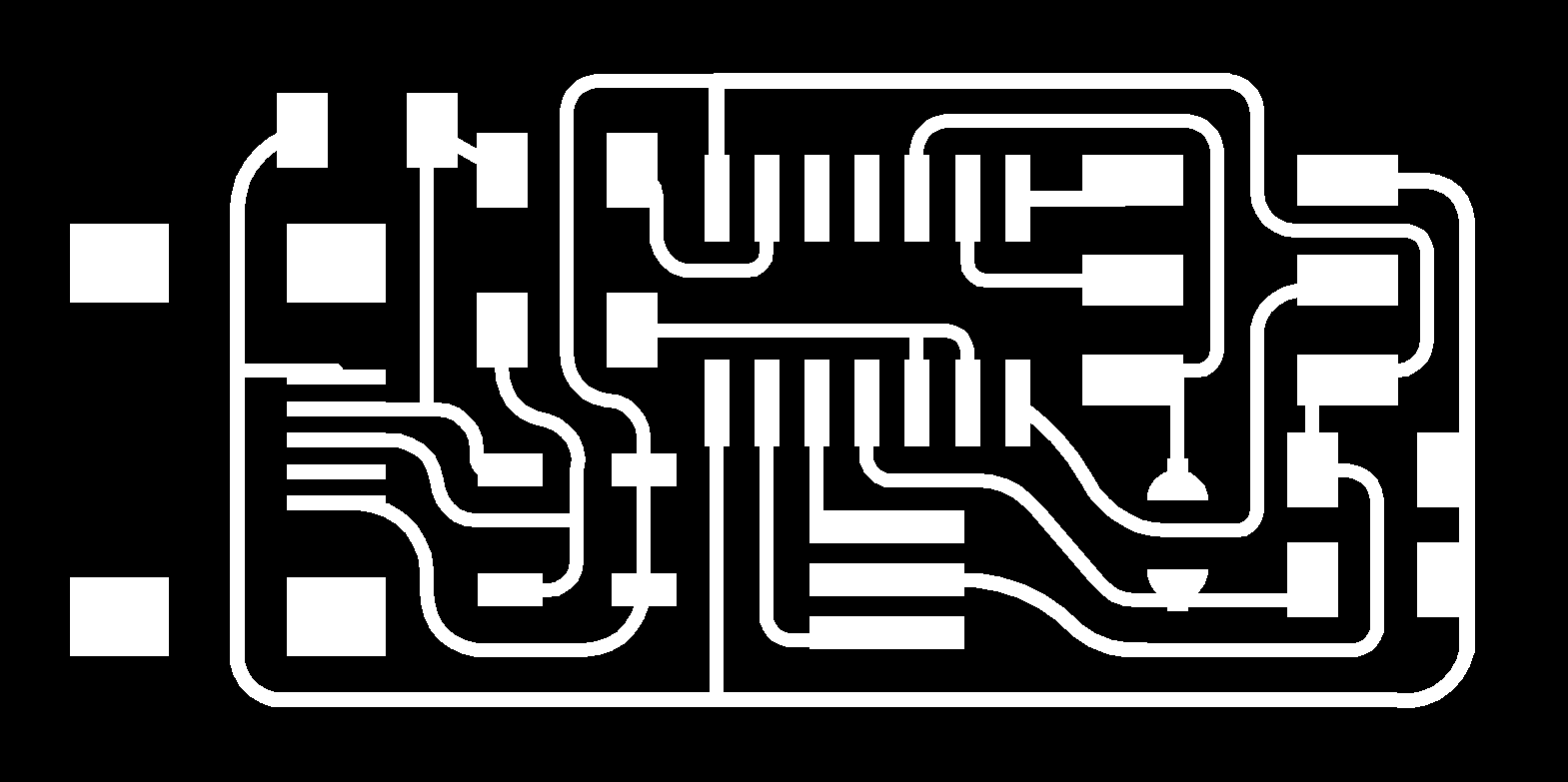


With the outline, I used a 1/32 endmill. Traces and outline must be prepared starting from the same image putting on/off the different layers so we can be sure that the 2 images will be milled starting from the same position.
Everything went well, ‘till I tried to remove the PCB from the stand using a screwdriver and a cutter (It was attached with a double-side tape). I ended ruining one of the traces so I milled a new PCB (I could have solved the situation soldering some tin between the 2 part of the trace…but I had time and copper plate so I preferred to mill a new one)
I also milled a different kind of FabISP, the one designed by Brian


To operate with the ShopBot we used its control panel (to find “Home” for the axis, upload the traces/outline file, start the machine).
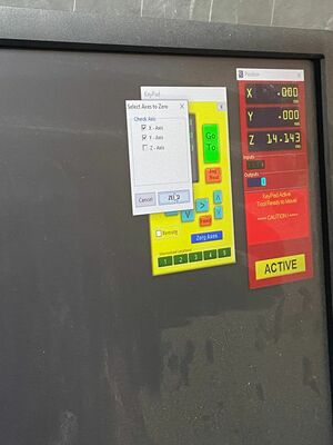
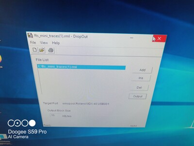
BUT…I wasn’t completely satisfied. I wanted to use the Roland MDX-40A ‘cause I have a similar one in my laboratory. Few years ago we have bought a new milling machine (a Roland MDX-540) that we use with wood and polyurethane, the old one isn’t used very often and my idea was to convert it in a milling machine just for PCB. I read the documentation and saw some video but…first problem…the VPanel to control the machine (an MDX-40, not an MDX-40A) is different and there’s no possibility to directly upload the files. I tried to update it but it didn’t work. I tried to force the machine connecting it to the Vpanel for the MDX-540…but it didn’t work. In the end I learned that there’s a software called DropOut that can do this connecting the milling machine like it was a printer. After I found it (two hours later…Roland I love your milling machine and your synths…but we have a problem with your customer support!) everything went well.
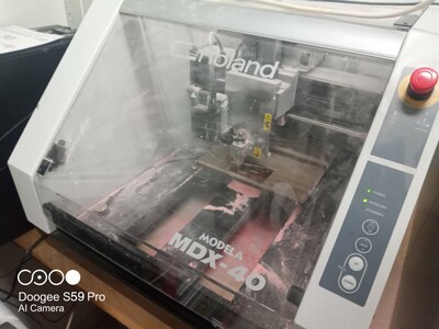
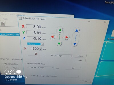
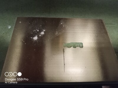
Uhm…not everything…I think I need to calibrate the worktable.
g **
__CNCporn...__
** ___ ## Soldering SMD components...how to weld them?! First thing to do...watch tutorials like [this](https://www.youtube.com/watch?v=fYInlAmPnGo&t=504s) and [this](https://www.youtube.com/watch?v=EW9Y8rDm4kE&t=323s). Then collect all the parts that you will need (according to the [BOM](https://resources.altium.com/what-is-a-bom-in-pcb-design)): - 1 ATTiny 44 microcontroller - 1 Capacitor 1uF - 2 Resistor 100 ohm - 1 Resistor 1.5K ohm - 1 Resistor 10K - 1 six pin header - 1 USB connector (was not available) - 2 jumpers - 0-ohm resistors - 1 Crystal 20MHz - 2 Zener Diode 3.3 V All the parts were available in the Fablab, excepet for the 1 Capacitor 1uF. We ask some advices to one of the OpenDot "residents" and he told us that using a different (but similar) capacitor should not be a problem (looking at the schematics). So we ended up using a 2.2uF capacitor. To keep them in the order I would recommend to tape them, preferably with transparent tape, to the list of components, as my Fabacademy collegues did. I didn't do this and I regretted... Before I started with the board, I spent some time trying to solder components (not SMD) on a practice board just to become familiar with the solder iron and the soldering process. Then I proceed to solder one resistor on a ruined PCB in order to define the difference between normal soldering and SMD soldering.  We were instructed to start soldering from the center of the PCB and always remember that some of the components must be soldered in a certain way/direction: **1. Microcontroller** you’ll see a little circle on one corner of the controller - usually it refers to the VCC pin **2. Crystel** has no polarity (doesn’t matter which way around) **3. Diodes** the polarity of the diodes is marked with a tiny line on the diode. this line has to be on the C pad as seen on the schematics **4. Resistor** no polarity **5. Capacitors** no polarity **6. 2x3 pin programming header** no orientation All the values (capacitors, resistors, diodes, crystels, ...) are marked on the diagram (first image on this page) so that you know which component is to be welded and where. In this moment I have a complete board, tomorrow with my instructor I'll try to upload the program to program (??!) the ISP and we'll see if everything will be ok.   I know that after having done the last passage I need to remove some components. I will update this page. ## Files 1. [Calibration test files (file ShopBot CNC-mill)](../files/week05/linetestfiles.7z) 2. [FabOptimus files (file ShopBot CNC-mill)](../files/week05/faboptimusfiles.7z)