5. Electronics production
This week was about Printed Circuit Board (PCB) ~ downloading a pre-given file, “milling” it on the Bantam Milling Machine and soldering the components on it. To test the success of the milling AND the soldering, a program will be loaded with a blinky code to flash the L.E.D.
Workflow for PCB Board
Workflow for Bantam Milling Machines This workflow was given to us by the director of our FabLab for us students to explore on our own of how to mill the PCBs. Rather than completely re-create the wheel, I have modified it to suit MY understanding and adding to it of items I think is important.
- Log into personal Google page
- Go to Tom’s Fab academy Google Classroom page
- Go to 328 Arduino - FAB UPDI created by Adam Harris
-
Go to updi_programmer_v17.brd and download to the desktop.
-
Go to Bantam Tools App(Milling page)
-
Open Files
-
Go to download and open updi_programmer_v17(1).brd
-
Open file and it will PCB will automatically be place the board to be milled at lower left corner.

-
Open same file again and it places it right on top of the current board to be milled. However go to “placement” for each RCB, and move X, 4 degree, move Y, 65 degrees and hit enter to shift a design to the lower right
-
Open file, go to placement for board and move x 55 degree and y 4 degrees - shifts the new board to upper left.
-
Open file, go to placement for board and move x 55 degrees and y 65 degrees - shifts the new board to the upper right.

- See red “highlights”, on any of the boards to be milled - enter BIT tool sizes (for each of the boards making)
Milling Tools
-
1/32 Flat End Mill Looks like a toothpick
-
PCB Engraving Bit 0.005” Angled like a pencil
-
Go to the bottom of the page and “Mill all boards” or else it will do only one at a time and you will have to change bits lots of times. AUGH!! Discovered this through self discovery.
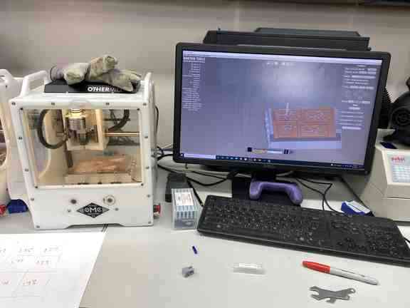
Preparation Phase Bantam Tool
Download file
-
Geber - this is an outdated program but still in use.
-
Eagle
-
SVG
Clean the Bed
-
Use vacuum and remove loose materials from previous user.
-
Wipe down with alcohol
-
Maybe custom probe variations in base plate level if printing more than one PCB on the same FR1 plate.
Configure the Bantam Tool
-
Select tool (end mill or engraving bit) by selecting change
-
Choose tool under New Tool
-
Install tool by loosening collet and replacing tool
-
Click continue
-
Verify tool position
-
Locate tool
Material
-
Select material - generic or FR1 At Latin we have been using the FR1 material
-
Measure the width and height of the conductive material you wish to mill (PCB - FR1)
-
Enter the width and height values.
Taping the Board
- Tape down the material using “nitto” tape used mill. (It is a double sided tape)
- No overlaps
- No wrinkles
The Z Height
-
Move probe over FR1
-
Click on Bit Breaker menu choice, upper left.
-
Probe Material Thickness
Check placement
-
Are you cutting material?
-
Are you too close to anything?
-
Align bracket on the left side
Move
-
Rehome - setting x and y origin
-
Origin
-
Loading - use this to load your material
Material Preparation Phase
- Open file
- Placement
- Scale
- Parts To Mill
- Engraving Cutout
- Engraving Depth - 15 mm
-
Milling Tools
-
Start Milling (if milling more than one item, scroll down to bottom of software program to where it should say “Start Milling All)
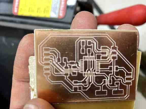
PCB Burrs
My set of milled plate had burrs on it from possible mill “chatter” for some reason. Zach who was helping me explore WHY it may have burrs asked if he could try rubbing them out using a metal ruler. Wasn’t a great idea because it scratched up the plate. Don’t think it made it useless however it didn’t make it as pretty. Instead using a plastic scraper IS the way to go.
However, to explore WHY there might have been some “chatter” or burrs (as Zach and Charlie called it) and some of the milled boards coming out useless, Barbara started exploring to see if the base plate of the Milling Machine might not be level across the machine. It was thought maybe because previous users have been using the dry wall metal scraper to get the milled plates off, that it has cause the overall machine plate to be out of alignment.
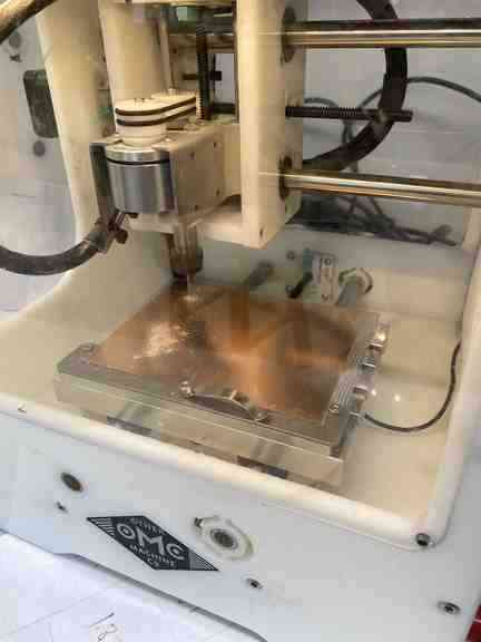
Barbara, with Zach and I watching, she used the Bit Breaker menu choice to Probe Material Thickness in nine different places on an FR1 Cooper sheet. The results are in the graph below. There are some differences from grid to grid in the layout. This suggest that maybe instead of doing a mass layout and milling that it needs to be done in sections for this particular machine. After completing section cuts with the same material thickness, reprobe for different sections of the material for new cuts??
| Probed thickness | on Machine # 2 | using FR1 Sheet |
|---|---|---|
| 1.87 | 1.85 | 1.87 |
| 1.82 | 1.77 | 1.83 |
| 1.81 | 1.74 | 1.78 |
UPDATE” Listening to Neils lecture, he described the burrs could also be a result of a new bit OR also an old bit that is overly dull. Bits have a general lifespan of cutting about 25 boards.
Soldering Paste vs. liquid pen vs. nothing.
I have been experimenting with my personal soldering capablity. In my opinion, when I use no flux, liquid or paste, my soldering appears horrible. Its just blobs of a mess and screams apprentice just learning. (Of which I am) Lucky for me, anything soldered has worked so far. I was recently introduced to liquid by the Lab while I searched for paste. I used paste in my youth for some electrical projects and wanted to give it a whirl again. Anyway, I find that I tend to over liquidfy the area I am intending to solder or the big issue because I move slowly, the liquid evaporates before I am ready. Recently I discovered some paste in a small store and I smile. To me I feel my PCB have a professional appearance to them. Minimal amount of solder and great connectivity. I am looking forward to further soldering with paste and would highly recommend it. The other advantage I find with paste is I feel it helps hold my parts I am soldering easier and with a touch of the heated iron, a sweet sound of fizzle and the part is attached.
Drag Soldering Tutorial Videos on YouTube
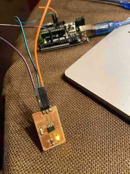
Soldered PCBs
These designs are from the director of Charlotte Latin FabLab and not my own. I did with my group mates collect the parts and personally soldered my own boards.
This first and second picture was done using no flux, liquid or paste. Doesn’t look great and marks the look of a beginners which is what I am HOWEVER…it works.

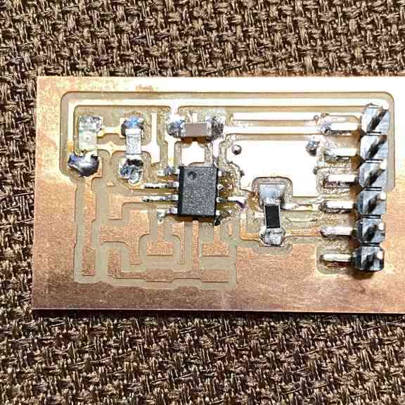
The next board was using paste flux and I LOVE paste. Not only did it help hold the components in place while touching to the iron, but also enabled, with a sizzling sound when the hot iron touched, minimal solder needed make the connection and solidify into place.

Programing
coming soon