4. Computer controlled cutting
This week was about making Vinyl Stickers from scratch, creating a Parametric Construction Kit out of Cardboard and exploring and getting detailed information on the Laser Cutters.
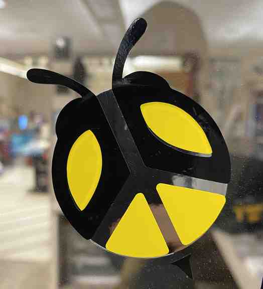
During the start of Covid, my wife and I made a wooden sign that had a bee on it with individual letters that spelled Kind to say Be Kind. Going with that idea to create a sticker I ended up using the words Bee at Peace and lots out there. Eventually came across this one that looked simple and ready to go.
Vinyl Stickers
Sticker Making Process for the “Peace Bee”
- Explore the web for idea of a sticker wanting to recreate.
- After finding the image, Screenshot it and save it (onto desktop)
- Import into a Corel Draw page
- Lock size ratio (3 inches for sticker assignment)
- Go to top tools and select “Trace Bitmap”
- Go to Outline Trace
- Go to Detail Logo
- Click ok
- Click on logo
- Slide logo to one page. There will be another left behind. Delete that one
- Slide logo back to page
- Create circle to go around back side of Bee to give stand out of the peace symbol
- Click on object
- Ctlr U to unlock objects
- Click on same color objects and group them together and pull them aside on page
- Click on circle that will be the background and pull aside on page
- Click on black body parts and pull aside on page
- Save
- Export as PNG file
- Save into FabLab personal folder
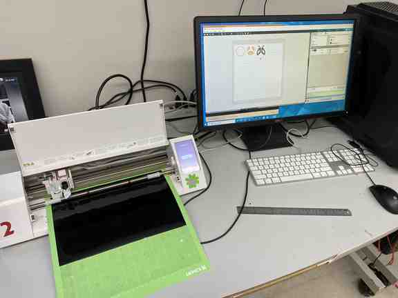
At the Lab and at the Printer.
- Open FabLab personal folder and download image onto desktop
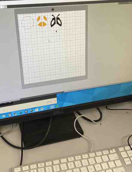
- Open Silhouette Studio and open file
- Even though Image was saved at 3” on Corel Draw oversized so had to resize back down.
- Because I had done it in Corel Draw it already was “traced” and ready.
-
Choose Vinyl Sticker colors. (Black - body and stinger, Silver - background, yellow - color to the wings)
-
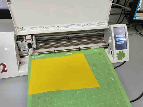
Had to choose one of two options when it came to printing. Either delete two body items and just print one item on the vinyl paper or print all three body parts on the same color. And do the same for two more different vinyl colors. I chose to print the same three items each on the same vinyl color paper and have some to take home and stick some other Peace Bee stickers elsewhere. The one I print is meant to go onto Tom’s office window so I would like to have a couple to take home and stick where I want them to go.
- Back to the printer, I had to stick the vinyl “paper” to the tacky mat that gets loaded into the printer. After the printer accepts the “load cut mat” on the Silhouette program, go to the bottom right and hit “send” one more time. This sends the final information to the printer to start cutting.
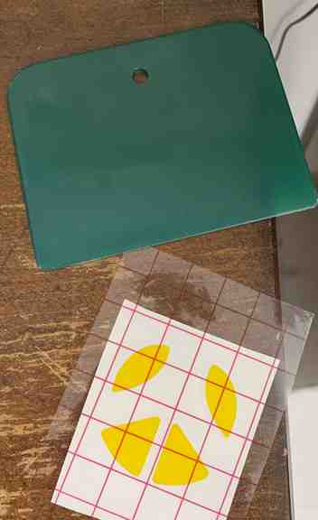
After printing: - Starting with the Silver circle, I needed to “weed” away the extra silver outside of the circle. I did not want to be a part of the sticker. - With the black, I had to “weed” away everything but the antenna and outline of the body and bee stinger. - With Yellow, I had to “weed” away the parts that were NOT going to be in the wing body.
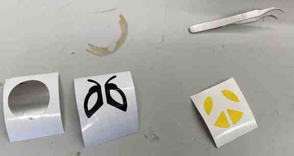
- After the “weeding” is complete on all three vinyl papers, used a “transfer sheet” to pick up the four yellow pieces. From there, laid those yellow pieces down on the black body outline and peeled both yellow and black gently off from their sticky paper and onto the transfersheet. Last layer to make was to lay the yellow and black layers onto the silver circle. Success!! Used a scraper to make sure all the layers stuck on to the circle and the transfersheet. Peeled them back carefully combining all 3 layers of the sticker.
Lastly, I stuck it on the office window of the Director for the Charlotte’s FabLab office and used the scraper to ensure that all three layers will stick to the window more than the transfer sheet. This sticker to be displayed with every FabLab student of the current and past years. Now to just pass FabLab 2022 so I don’t have to scrape it off and instead walk by the window with pride.
Parametric Construction Project
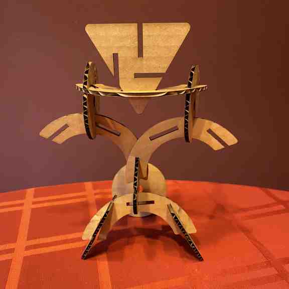
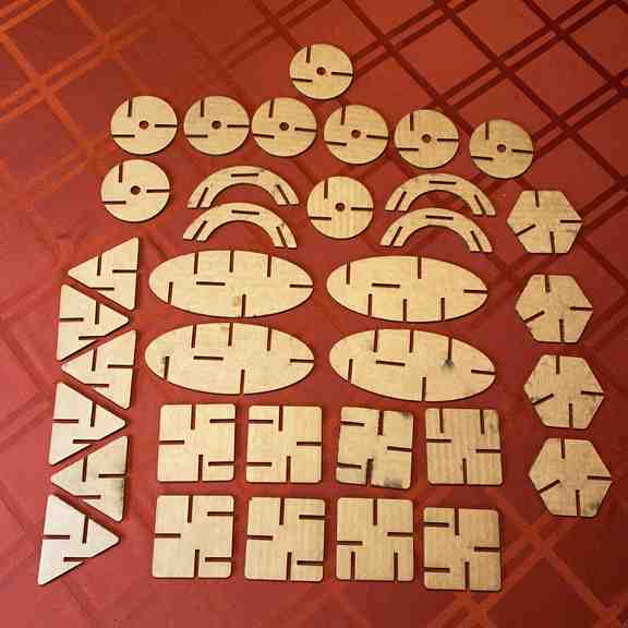
The purpose of this particular assignment was to create a “Parametric Construction Kit.” The end result of that kit produces (at least for me) cartboard cutted shapes that are notched to fit / slide into each other so someone could assemble a creation. The shapes in the picture are the ones I choose to make from scratch.
The Process I used:
- Step 1:
Choose a Computer-Aided Design (CAD) program such as FreeCAD, Fusion 360, Inkscape, Cuttle, Solid Works etc from the list provided and suggested from Fab Academy. These programs have the ability to have a Parametric data table within the CAD program for the designer to utilize as a shortcut. A shortcut in two ways that I have discovered so far: 1. After creating a rectangle (or any other shape) and getting to enter the size and dimensions, instead of typing 0.125 + 0.010 or typing 0.130 (the sum of the two numbers) for the width of 25+ rectangle I want made, I can simply type the letter “k” and the numbers is automaticly inserted. That quick. This method also, MOST IMPORTANTLY, should I have to go back and change the numbers because of a goof becomes a huge time saver. Say I need the new size of my width to be 0.135 instead of 0.130 I can go into the parameter table and change that particular data set and after entering the new data, all rectangles that I had made gets automaticly altered. If I didn’t do this, then I would be required to make the changes 25+ times one by one on this particular assignment. No thank you!! This Parameter table can be done prior (and is recommended) to making objects so all would be changeable. However parametric table can be created anytime throughout the project however any objects made prior to creating the table would not be included in the data set. So far I have discovered the Parametric table can be used for anything where the designer may need to input data such as length of shapes, circles, and angles.
So in choosing the CAD program, in the end choice I went to Fusion 360. I have limited experience with CAD in general however I have begun to understand the basics enough whereas any other program I would be needing to start from scratch. I decided I haven’t the time for that after trying FreeCAD.
The ONLY drawback to Fusion 360 that I discovered after I completed the design of the Parametric Construction Kit, that saving the file needs to be done by DXF format which Fab Academy does not accept or the laser printer does not recognize. However the format, SVG is not an option. The work around that is, Latin laser printers use Corel Draw can read the DXF file and from there the designer can save it as a SVG file. If that is the only drawback to Fusion 360, I’ll continue to show my loyalty to that CAD program.
- Step 2 ~ Creating the Shapes
Evidence left around the lab indicated that other students were making their shapes about an inch maybe inch half big. Whether it was for testing their design or their actual design I haven’t asked YET.
- 1st attempt: I made my first design of a 2 inch long rectangle by 1 inch wide on Fusion 360. I ran into trouble in needing to make the slots for the pieces to go slide into another rectangle. I think it turns out that after making the rectangle I was hitting the “finish sketch” button so the rectangles I was attempting to put on for the slots was failing to connect. Thankfully Graham a student was around to share that tip with me. So the “finish sketch” button should not be used until ready to move away from that particular shape and all modifications are complete. So I learned to make the slots and complete four sets of rectangles.
I really had no clue how deep to make the slots or how wide to make the slots. (This is where I run into trouble with “self discovery” vs being taught.) Using a calibration tool in milimeter mode and measured the thickness of the cardboard to use that as the grounds for how wide to make my slots. Sized to 3.8mm. I chose to keep the depth of the slot the same to keep things simple. Declaring myself complete for a sample test on the laser, I gave it a whirl. FAILURE. The slots were too wide to the point there was absolutely no friction to hold one rectangle piece to the next rectangle piece. And the slot had no depth to allow two cardboard rectangle to slide in onto each other and stick. Too wide and not enough depth. Lesson thought to be learned. And to top it off, I had not used the Parametric table YET as I figured this just to be a test sample however I then had to go back and change all my numbers on the slots one by one by one.... I also had to learn to modify the slots and the rectangle by using the trim tool that would enable the laser to cut from the rectangle down into the slot groove. This set of four is marked by the yellow pencil and the “x” mark on the cardboard.

- Second attempt: Not sure why I thought simply changing the numbers slightly to make the slot just slightly narrower and add depth 3x’s deeper (13mm) would make a difference. Appearance you can see from the first set of four retangles with an X on them to the newer four set of rectangles with a squiggly line however result is still FAILURE. At this point I was about three hours in and it was 10pm. There were extra students around the lab so I decided to pause, take a brain break of what I was doing an go explore to see the different projects. This next set of four is marked with a squiggly line and the orange and white pen to the row.
From one student (Aaron) share that he had used the Kerf measurement from his group’s week 3 project. That’s when understanding of Kerf made sense and how to apply it to the Parametric table. Duh. So I drew up my formula in the notebook, width of cardboard + kerf discovered from group project = measurement to use. Tom the director of our Fab Lab happened to walk in so I asked him to see if I was on the right track. I sort of was, however my measurement of cardboard thickness was off. Tom wouldn’t tell me and instead he had me grab the Calibration Tool, a sheet of cartboard and show him how I was measuring. Tom suggested that I use inch mode vs. milimeter mode. My measurement of cardbaord was .150. Tom said it was too much and that for conversation purpose, explore .130 however I needed to go explore cardboard measurements a bit more. So another student mentioned that the width of the cardboard is supposed to be 1/8 inch which is 0.125 to a decimal conversion. Crapola. My measurements where off as to my understanding. Now I understand.
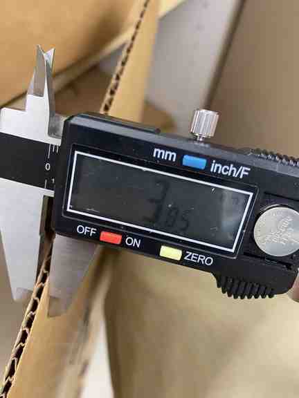
New measurements to insert into the Parametric Table was to be: 0.125 + 0.010 kerf to equal 0.135 The kerf number comes from my groups discovery process from the Laser Pro. The other group had .012. Don’t know how much a difference of 0.002 might be however I know my group worked hard to get our results so I used that.
- Third attempt: Knowing I wanted to get home before midnight I did a quick change on the rectangles I already had used so the width of my slots was 0.135. Sent it to the laser and hot diggity dog it was a perfect fit!! Done for the night. This set is marked by the blue pen and smiley faces on the cardboard pieces.
- Fourth attempt: Awoke early in anticipation of working more on this project now that I truly understood and had correct dimensions to insert into the Fusion 360 Parametric table. Creating the shapes and using the pre-set parametric table to help create the slots made everything a breeze. At 4am, I thought - if successful, I have an idea I would like to create into my 3rd and 4th grade lesson plans and small shapes won’t be ideal. So I chose to make my objects 3 inches big and extend my slot depth to one inch. The reason for the extension of the slot depth is to allow the construction kit pieces not to be dependant on sliding into one groove of one shape to the next groove of another shape to hold itself. Fortunes would have it, my son was invited to a friends house for a playdate and my daughter had to go to a birthday party near the school so I could sneak into the lab and see if I could print my new objects. I did and I was met with success. Wholly molely cow!!!! SUCCESS!!


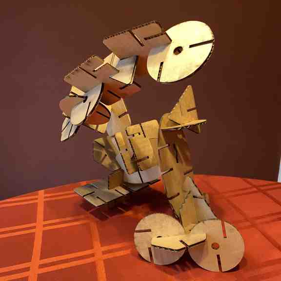
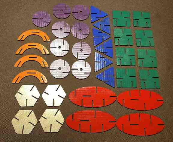
I did spray paint the pieces to make them a tad more attractive because I have a very active kid who needs to have projects to tinker with or help me on. An after thought is, hope that doesn’t make the pieces too tight. Or tacky as it seems the paint, while dry seems sticky to the touch.
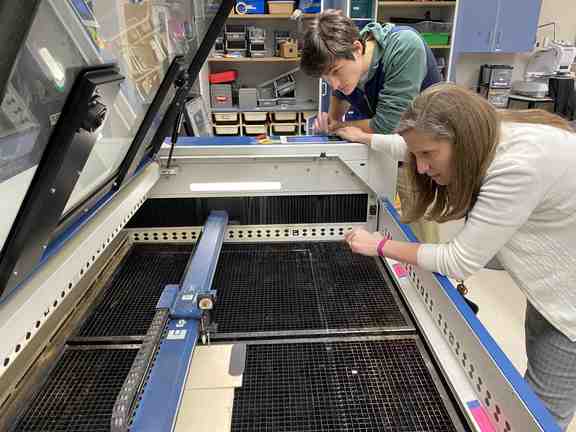
Group Project
To characterize the Charlotte’s Fablab Lasercutter’s focus, power, speed, rate, kerf, joint clearance and types.
(The AWESOME) Group: Avery, Barbara, Charlie, Nidhie and myself.


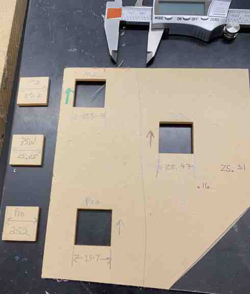
Type of Laser Cutters:
- Epilog Fusion Pro __ Watt
- Epilog Fusion M2 50 Watt
- Epilog Helix 35 Watt
- Epilog Helix 30 Watt
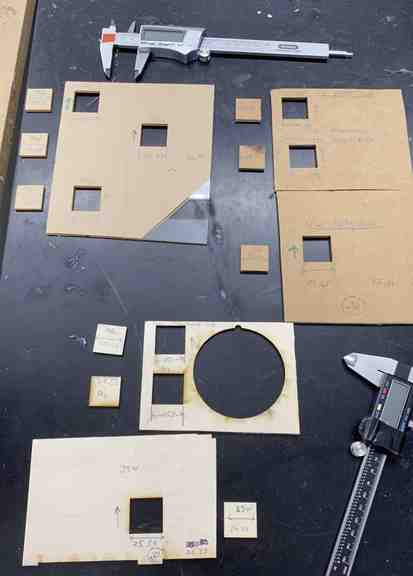
Kerf: the material that disintegrates due to the laser cutting. The measurements for Kerf is taken by the intended size, for example: a one inch square BEFORE cutting minus the actual size of the square AFTER the cut measurement divided by 2 to equal the kerf. The dividing by two comes from using a square as a sample test cut and when measure the 1 inch square we are actually measuring the cut from two sides. Hope this makes sense.
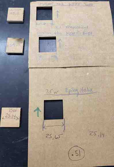
| 1/8 Cardboard | intended size | minus | after cut size | # ÷ 2 | = kerf |
|---|---|---|---|---|---|
| Fusion Pro | 1 inch | minus | 0.972 | 0.028 ÷ 2 | = 0.014 |
| Fusion M2 | 1 inch | minus | 0.990 | 0.010 ÷ 2 | = 0.005 |
| Helix 35 Watt | 1 inch | minus | 0.989 | 0.012 ÷ 2 | = 0.006 |
| Wood | intended size | minus | after cut size | # ÷ 2 | = kerf |
|---|---|---|---|---|---|
| Fusion Pro | 1 inch | minus | 0.99 | 0.010 ÷ 2 | = 0.005 |
| Fusion M2 | 1 inch | minus | 0.991 | 0.009 ÷ 2 | = 0.0045 |
| Helix 35 Watt | 1 inch | minus | 0.994 | 0.006 ÷ 2 | = 0.003 |
| Acrylic | intended size | minus | after cut size | # ÷ 2 | = kerf |
|---|---|---|---|---|---|
| Fusion Pro | 1 inch | minus | 0.989 | 0.007 ÷ 2 | = 0.0035 |
| Fusion M2 | 1 inch | minus | .990 | 0.01 ÷ 2 | = 0.005 |
| Helix 35 Watt | 1 inch | minus | 0.993 | 0.007 ÷ 2 | = 0.0035 |
Useful links
Because Fusion 360 does not save as a SVG file, and our Fab Lab laser cutters automatically converted to Corel Draw when transfering the file to be printed, I needed to share that Fusion 360 file in the Corel Draw converted format and the SVG converted format shared below.
-
CorelDraw converted file of the Fusion 360 Parametric Construction Kit
-
SVG converted file of the Fusion 360 Parametric Construction Kit