10. Output devices
During this week, I worked on adding an output device to a microcontroller board I designed, then programming that to do something. I utilized this week towards my final project development and used 12V geared DC motors as my output as those are the motors I am going to use in my final project
Initial Research on Motors and Motor Drivers
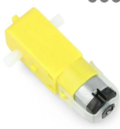
Coming into this week, I thought I was going to be using 4 stepper motors to move my robot for my final project around. However, after doing some research and speaking to my lab director and instructer Mr. Tom Dubick I decided to change my mind. Essentially, a stepper motor is more precise with its rotations than I need for my robot, so using a dc motor would make more sense. I used a Geared DC Motor in order to convert the high speed of the DC motor into torque.
This is the link to a motor similar to what I ended up using with an image below
In addition to the motor, I chose to work with a motor driver. Using this website, I learned that a motor driver essentially acts as an interface between the motors and the control circuits that takes the low-current control signal and then turn it into a higher-current signal that can drive a motor.
Since I will have 4 wheels on my robot, I decided to use 2 motor drivers that control two motors each. The motor driver I selected was the L298n Motor Driver Module with H-Bridge.

I spent a lot of time researching and watching videos on how these motors and motor drivers work. Believe it or not I have never actually worked with a motor of any kind.
Initial Research
I started by surfing youtube videos on the motor driver and how to make it work with an arduino. I found this video by MRMS - WORKSHOP that really helped me understand the whole concept. I also found this video to supplement my understanding. The video was long, so I only watched the parts about hooking up the driver module to an Arduino.
After watching the videos, I found this website that gave amore indepth explanation in writing and went further into explaining the motors
These videos and websites really helped me gather the information on what I was trying to do. They outlined the wirings, code, and explanined the reasosn for both of those componenets. Through the website, I learned that the enablers coorespond to speed control and the IN pins coorespond to direction for each motor. For my project, I did not really care much about the speed, but more about the direction.
Modeling on TinkerCad
In order to get a better understanding of what I was doing, I decided to create a model on tinkercad of what I was planning on doing. I started by adding two of the motors I was going to use, and adding the L293D motor driver to control these motors.
I referenced two websites to get the pinouts of the two different motor drivers to compare them, L298N and L293D. The L298N that I had in the lab was a module, while the 293D was a chip, but they both had similar pinouts, so I decided to go ahead and continue on tinkercad.

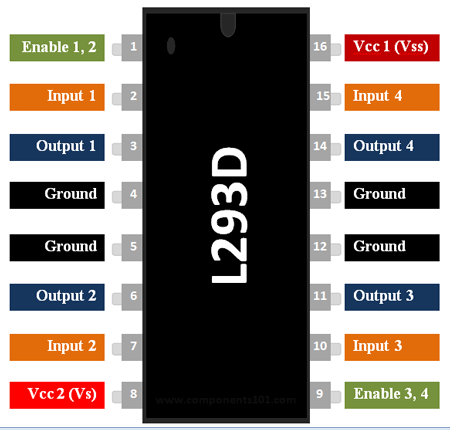
I referenced the pin outs above and wired it accordingly. Through the website, I learned that the enablers coorespond to speed control and the IN pins coorespond to direction for each motor. I also added an arduino and a 4 double A battery pack. I also added an arduino and a 4 double A battery pack.
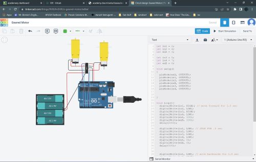
After I connected the wires, I started playing with the code. I found the initialization code from the website listed above, so I brought that over to tinkercad and started playing around with it. I changed the in1 through in4 values and the enablers values according to the pin out of the L293D pinout and my connections
I also found this table that showed the spinning directions of the motors.
| Input1 | Input2 | Spinning Direction |
|---|---|---|
| Low(0) | Low(0) | Motor OFF |
| High(1) | Low(0) | Forward |
| Low(0) | High(1) | Backward |
| High(1) | High(1) | Motor OFF |
Using this, I changed the code in tinkercad to experiment.
The code I used in tinker cad was:
int in1 = 2;
int in2 = 4;
int enA = 3;

int in3 = 5;
int in4 = 7;
int enB = 6;

void setup()
{
  pinMode(enA, OUTPUT);
  pinMode(in1, OUTPUT);
  pinMode(in2, OUTPUT);
  pinMode(enB, OUTPUT);
  pinMode(in3, OUTPUT);
  pinMode(in4, OUTPUT);

}

void loop(){
  digitalWrite(in1, HIGH); // move forward for 1.5 sec
  digitalWrite(in2, LOW);
  digitalWrite(in3, HIGH);
  digitalWrite(in4, LOW);
  delay(2000);

  digitalWrite(in1, LOW); // STOP FOR .5 sec
  digitalWrite(in2, LOW);
  digitalWrite(in3, LOW);
  digitalWrite(in4, LOW);
  delay(500);


  digitalWrite(in1, LOW); // move backwards for 1.5 sec
  digitalWrite(in2, HIGH);
  digitalWrite(in3, LOW);
  digitalWrite(in4, HIGH);
  delay(1500);

  digitalWrite(in1, LOW); // STOP FOR .5 sec
  digitalWrite(in2, LOW);
  digitalWrite(in3, LOW);
  digitalWrite(in4, LOW);
  delay(500);

}
Working with Real Arduino
After I got the motors working on tinkercad with the L293D chip, I decided to model it with an actual Arduino and a L298N Module Motor Driver.
I gathered all my parts:
- L298N Module Motor Driver
- 2 Geared DC Motors
- Arduino
- 8 Female to Male jumper wires
- 9v Battery (used instead of AA battery pack)
Since I was still wokring with an arduino, I was able to use the same code I used in tinkercad, the only different was I had to wire them differently into the module, but that was very easy considering I had the pinouts and the website. I plugged everything in, and the module lit up.

After connecting, I uploaded the code into the arduino, and run the program to get the motors working. IT WORKED!
PCB Designing
Now that I had the motors working with an arduino, my next step was to design a pcb to replicate the arduino and have the motors run off of that.
Design 1
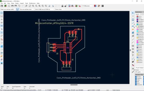
I got onto KiCad and started by adding an Attiny 1614. I decided to use the 1614 becasue the Attiny 412 did not have enough pins to make connections with all the EN and IN pins in the module to run both motors.
Along with the 1614, I added 2 sets of 3 pin headers to connect to each of the motors EN and 2 IN’s, and I added and another 3 pin header to supply power, ground, and a UPDI pin. I carefully looked at the pinout of the 1614 in and connected three pins to three headers accodring to the pin out in order to make life easier when I made traces in the pcb designer.
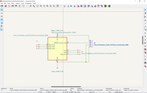
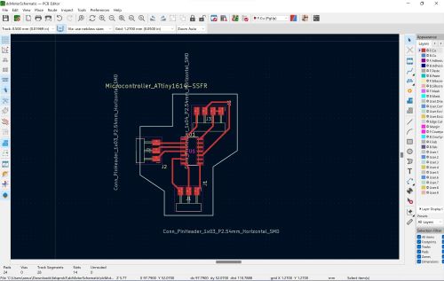
I then went to the PCB editor part of KiCad and started drawing my traces following my documentations from Electronics Design Week. Here is what the pcb looked like
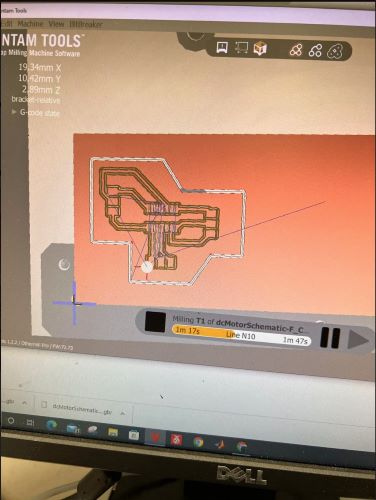
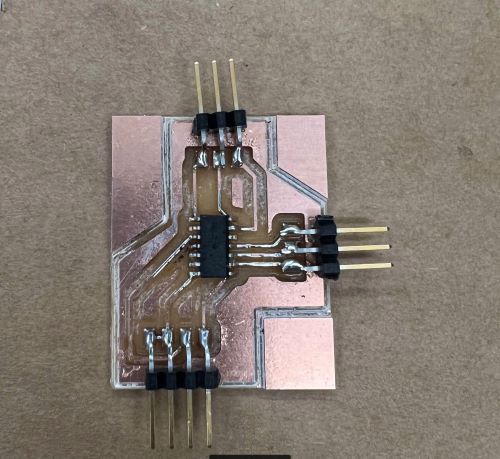
I sent the file to the Bantem Milling Machine and milled my board.

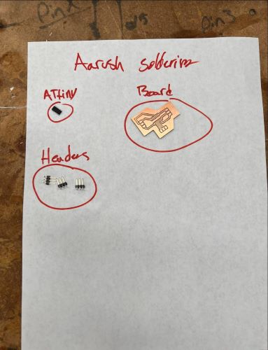
After I milled my board, I had to popualte it with the componenets I was going to use. My design only required me to use 3 sets of headers and an Attiny 1614 chip.
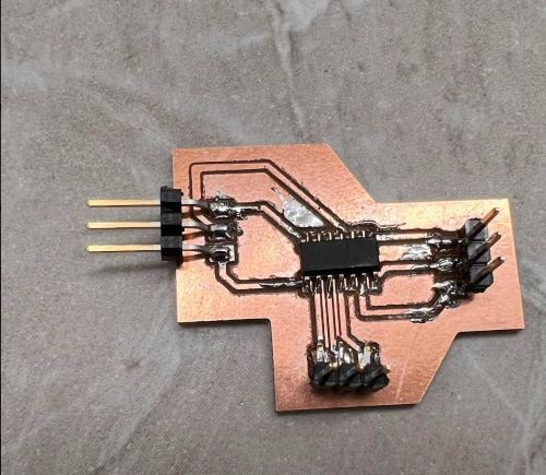
Once I was done soldering, I took my PCB to my arduino to upload code into it.
I connected the power, ground, and updi pin from the pcb to the arduino.
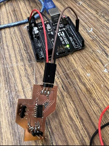
Then I uploaded the code onto the chip

It uploaded!
It was at this point I realized I needed a common ground between the pcb and the motor driver in order to get the driver to work.
Design 2
I went back to KiCad to add an extra pin for my ground. I kept everything else the same, just adding an extra header connected to the ground header I already had.
I again milled this new board, and uploaded code into it using my programmer.
The code compiled, and was able to upload into the 1614 chip.
I then connected in the respective wiring from the 1614 board to the L298N motor driver and ran code.
Voila!
What I learned
Through my fabbing this week, I learned a lot. It was my first time using motors and a motor sheild, so I familiarized myslef with both of them while also creating a pcb board to control the motors. I experimented with different code in order to figure out how to control the motors. My next step is to duplicate this process and mill a pcb to work for my other set of wheels.
Group Work
The group assignment for this week was to measure the power consumption of an output device. Jack, Andrew, and I worked together to test the power consumption of a Servo Motor. We hooked up VCC and Ground to the servo and spun a potentiometer to see the changes in power output on a multimeter.
You can find more information about the group work on the group site.
Files
You can find my files for this week here