4. Electronics production
During this week, I worked on making an in-circuit programmer that includes a microcontroller. I milled and populated boards in order to complete this task. I also worked on our group project, which was to characterize the design rules for our in-house PCB production process - essentially make a work flow.
Introduction to In Circuit Programming
Before the official start of Fab Academy, I was taught about in-circuit programmers and what they are used for by working with an AT Tiny 412 chip.
ATtiny 412 Board
We were tasked to make an LED blink, but instead of doing it with an arduino, we had to convert the arduino into a bootloader and use that to run the program on a PCB board with an ATtiny 412 chip. The board was designed and miled for us by Dr. Adam Harris and Mr. Tom Dubick respectively.
I started by soldering all the components onto and populating the PCB board which would house the ATtiny chip. I had a lot of prior experience with soldering, so I was used to working with small pieces. I was lucky to have no bridges or ripped traces while populting this board on my first try, so I was able to get it done fairly quickly.
This is what my board looked like

Using Arduino as a Programmer
After populating it and making sure the ATtiny board worked, it was time to convert the arduino into a bootloader so it could program the board I made.
I started by downloading the arduino software from their website and followed the steps on this website. I layed the basics of the steps out below
Installing the MegaTineCoreLibrary into Arduino
The library allows arduino to recognize the ATtiny 412 chip I used in its program.
To install the library i followed these steps:
- Open the preferences window from the Arduino IDE. Navigate to File, then Preferences
- On the preferences window, find the “Additional Board Manager URLs” text box and type the following
http://drazzy.com/package_drazzy.com_index.json
- Next, navigate to the “tools” drop down menu and go to “boards” then “board manager”
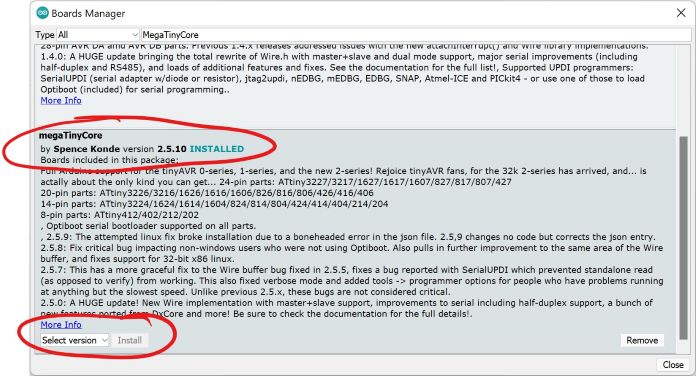
- Search for megaTinyCore in the search bar near the top and find “megaTinyCore by Spence Konde” The window will look like this:
Making the Arduino into a Programmer
To make the Arduino into a programmer, I first downloaded the files from this github repo. I moved the zip file to my desktop and extracted it there (note - make sure to remove the word ‘master’ in any file name it shows up in to avoid complications this caused errors for me when I was tring to work with the code. Do this because the arduino IDE wants all arduino files to be in a folder with the same name).
Next, open the file called
jtag2updi.ino
This should open up many different files, and one of them should be blank. After you have it opened up, connect the arduino to the computer.
When plugging my Arduino into my computer, I made sure of two things: 1. Port: COM 8 Arduino Uno (varies) and 2. Boards: Arduino Uno
After all this was checked, I compiled and uploaded the file into the arduino. It blinked two times letting me know all was good and the arduino was programmed to be a programmer.
Using Arduino to Program Blink Board
Now that I had an Arduino that acted as a programmer, I was tasked with using it to program the board with the ATtiny chip to blink.
I opened a new “Blink” code file.
// the setup function runs once when you press reset or power the board
void setup() {
  // initialize digital pin LED_BUILTIN as an output.
  pinMode(0, OUTPUT);
}

// the loop function runs over and over again forever
void loop() {
  digitalWrite(0, HIGH);   // turn the LED on (HIGH is the voltage level)
  delay(1000);                       // wait for a second
  digitalWrite(0, LOW);    // turn the LED off by making the voltage LOW
  delay(1000);                       // wait for a second
}
At first, I was having errors somesort of error, but then realized I had to configure the pinMode in the code to be the necessary PIN of the ATTiny412 Chip instead of the Arduino PIN as I had learned to do before. ATtiny 412 chips usually have it at PIN 4. After I did this, I went into the tools drop down menu and edited port and board: 1. Port: COM 8 Arduino Uno (varies) and 2. Boards: AtTiny412/402/212/202
After I compiled, I ran the code into to the board with the ATtiny chip and it worked
SAMD11C Board
After the success with using the arduino as a programmer, my next task was creating my own programmer using a design given to me by Mr. Dubick and Dr. Harris. Using Dr. Harris’s documentation, I got to work.
Milling Board
Following the website, the first step was to mill my own board that I could populate with the SAMD chip and all the other components. The website contained a link to a github repository that had the files for the board inside the ‘Gerber’ folder.
Following this workflow provided by Mr. Dubick and our own workflow we created on the group site, I began milling.
I started by secruing the pcb copper sheet to machine by applying nitto tape to the bottom of the copper and fastening it securly to the machine.
At this point I realized one of the rubber bands that spun the bit was broken

I troubleshot the issue online and found it was a veru simple fix, and it had even happened before in our ab. I simply took a spare rubber band and replaced the broken one.
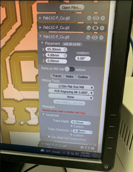
I then uploaded the files into Bantam Tools software, both the traces and the edge cut. I also added both the 0.005” PCB engraving bit and the 1/32 flat end mill bit to the tools, as one was meant to cut the traces while the other to cut the board out of the sheet. I uploaded both files twice just incase I ripped a trace while populating one of them.Next I changed the both the trace clearance and trace depth to 0.25mm. I then changed the bit inside the machine to 0.005” PCB engraving bit, followed the steps on the workflow, and started milling.
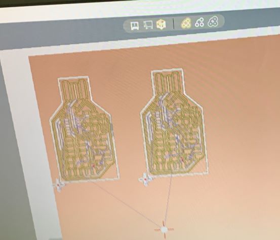
This is what it looked like after milling
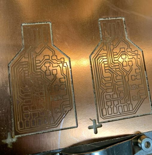
I took the boards out of the copper, rinsed it under water to get rid of the copper shavings and dried it off

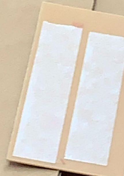
The result looked good, so I started soldering. as I got to work, I saw that some of the traces looked off.

I put my board under a microscope to see if anythign was actually wrong, and to my dismay, the traces were not milled properly.

I now had to start over.
Second attempt
I thought maybe it was just one time mistake, so I tried milling again with the same settings and the same trace clearance and trace depth. This time, I decided I would only start by milling one board to save some material, and if it worked I would make another. I went through the same process again, following the work flows, and milled my board.
Did it work? No.
The board had the same mistake. The traces were too thin

Third attempt - Success
When I went in for my third attempt, I knew I had to change some of my settings. When I went to mill, Mr. Dubick told me to try setting the clearance to 2.00 mm and use the 1/64 in flat end mill bit instead of the 0.005” PCB engraving bit. I followed his instruction and the board turned out really well.

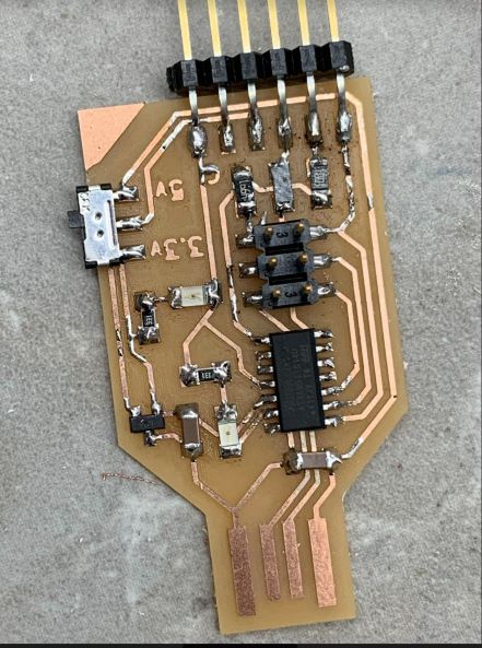
The traces were thick and clear so I could easily see there was no discrepancies. I rinsed the board off and started soldering.
Using files from the github repo, I soldered these components onto the board. This is what the finished board looked like
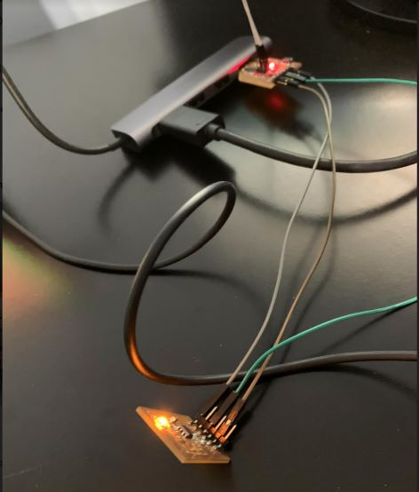
I put the board into the USB of my computer, and one LED turned on, indicating it was working.
Making SAMD into a Programmer
The next step was making the SAMD board into a programmer. Following Dr. Harris’s documentation, I got hold of an Atmel ICE created by fellow student Alaric Pan to program my programmer.
Following the documentation, I plugged in the wires in their correct places.

I then downloaded the edbug 31 and the arduino firmare listed on the site, put them in the same folder, and run the following command on the command line in the folder:
edbg-windows-r31.exe -bpv -e -t samd11 -f sam_ba_Generic_D11C14A_SAMD11C14A.bin

It worked.
Next, I went into the arduino IDE and pasted
https://www.mattairtech.com/software/arduino/package_MattairTech_index.json
into the additional board manager URLs, and went to tools, then boards, board managers and I installed the library for the SAM board by MattairTech.
Then I selected Generic D11C14A as my board, and uploaded this code to see if it worked
int led = 2;

// the setup routine runs once when you press reset:
void setup() {
  // initialize the digital pin as an output.
  pinMode(led, OUTPUT);
}

void loop() {
  digitalWrite(led, HIGH);   // turn the LED on (HIGH is the voltage level)
  delay(1000);               // wait for a second
  digitalWrite(led, LOW);    // turn the LED off by making the voltage LOW
  delay(1000);               // wait for a second
}
It did. To make my board a programmer, I uploaded this code into it.
void setup() {

   SerialUSB.begin(0);
   Serial1.begin(57600, SERIAL_8E2); //Adjust baud rate and use SERIAL_8N1 for regular serial port usage

  /*Trigger the reset line for the UART.
 This is supposed to trigger the target board's reset as if it is the RTS line. I couldn't figure out the SERCOM setting for
this in the SAMD11C datasheet*/
  pinMode(5, OUTPUT);
  digitalWrite(5, LOW);
  delay (100);
  digitalWrite(5, HIGH);
}

void loop() {
   if (SerialUSB.available()) {
      Serial1.write((char) SerialUSB.read()); //Send stuff from Serial port to USB
   }
   if (Serial1.available()) {
      SerialUSB.write((char) Serial1.read()); //Send stuff from USB to serial port
   }
} //end loop
Finally, the baord was a programmer. I changed the programmer settings in tools to the SerialUPDI - SLOW: 57600 baud and worked to make the board program my ATtiny 412 board by uploading this code:
void setup() {
  // initialize digital pin LED_BUILTIN as an output.
  pinMode(0, OUTPUT);
}

// the loop function runs over and over again forever
void loop() {
  digitalWrite(0, HIGH);
  delay(800);
  digitalWrite(0, LOW);
  delay(800);
}
Group Work
In addition to our individual work, we were assigned a group task to characterize the design rules for our in-house PCB production process. I did this by creating the after milling section of our workflow found on our group site and by contributing to the group milling process in the steps of removing the milled product anc cleaning it off.
Summary
Through my work this week, I learned extensivly about the milling process in our lab and worked to solidify my understadning of Microcontrollers. I learned that Microcontrollers are useful to program other boards and can either by made from arduinos or our own designs. I also encountered my first cases of traces ripping while working, which was a pain. I learned how to best avoid this situation by handling my boards with care.