
GUIDE
- Circuit Design
- Mill
- Solder
- Test
What questions need to be answered?
BOM
| COMPONENT | DESCRIPTION | DATA SHEET | SPECIFICATIONS | COST |
|---|---|---|---|---|
| ADXL343BCCZ-ND | 3 axis accelerometer | ADXL343-Datasheet.pdf | MAX V s / V DD = 3.9v | € 2,53 |
| ATtiny1614 | More pins than the ATtiny1614 | ATtiny1614-16-17-DataSheet-DS40002204A.pdf | Polarity | € 0,64 |
| Capacitor (1µF) | To stabilize power signal. | Non-polarity | € 0,08 | |
| Resistor (0 Ohm) x2 | To use as a bridge for tracks to run underneath. | Non-polarity. | € 0,16 | |
| Resistor (1k Ohm) x2 | To control amount of current going to the Red + Green of the RGB LED | Non-polarity. | € 0,16 | |
| RGB LED, CLV1A-FKB | RGB colour combinations. | CLV1A-FKB_RGB-LED-datasheet.pdf | Polarity | € 0,34 |
| Resistor (499 Ohm) | To control amount of current going to the Blue of the RGB LED | Non-polarity. | €0,08 | |
| Button switch B3 SN | Input source. | Non-polarity. | € 0,83 | |
| Vibration motor 3v | Small vibration motor | Vibration Motor datasheet | Non-polarity. | € 0,98 |
| Resistor (1k Ohm) x1 | To control amount of current going to the vibration motor (and therefore speed) | Non-polarity. | € 0.08 | |
| Resistor (4.9k Ohm) x2 | ‘Pullup’ resistors to control amount of current going to the SDA + SCL lines | Non-polarity. | € 0,16 | |
| Button cell battery holder, smd | Holder for 3.3v CR2032/35 series button cells | bat-hld-001-thm.pdf | Polarity. | € 0,24 |
| Single sided copper board - FR4 | The PCB on which to mill and solder components. | 127,0mm x 76,2mm, 1oz | € 4,65 | |
| Adhesive Copper Foil | A tiny bit to fix the battery contact issue | € minimal |
| TOTAL: | € 10,85 |
|---|
All components sourced from Digikey.
Machines & Software used
- KiCAD
- Adobe Illustrator
- Mods
- ROLAND ModelA MDX-20 3D Milling Machine
For details see Week 4 - electronics production
What I did
Circuit Design
By comparing the different circuits from Week 10 - Inputs, Week 12 - Outputs and, Week 13 - Networking & Communications, i made a list of all the components from the different working circuits. I removed the duplicate components and was left with what i thought was necessary to begin designing the circuit.
- Footprints

What was missing was a power source small enough and mobile enough to fit on a wrist (a button battery cell). As the choice of using a ATtiny1614 meant i had several pins left over I decided to add a vibration motor for extra haptic feedback. These both weren’t in the Fabacademy inventory (or at least not in the form I needed) so I had to create foot prints from scratch so that they would appear in KiCad.
Taking dimensions from datasheets, I designed a footprint for the vibrating motor and a through hole mounting for the battery holder (this is mounted on the back of the PCB board).
The difficulty in designing the board was to arrange everything in as small an area as possible, as the size of the PCB would define how big the wrist band would be. As I would expect the device to be used by children too.
Milling

After all the issues in the past behind me, this went very smoothly, even the making of through holes which i had never done before.

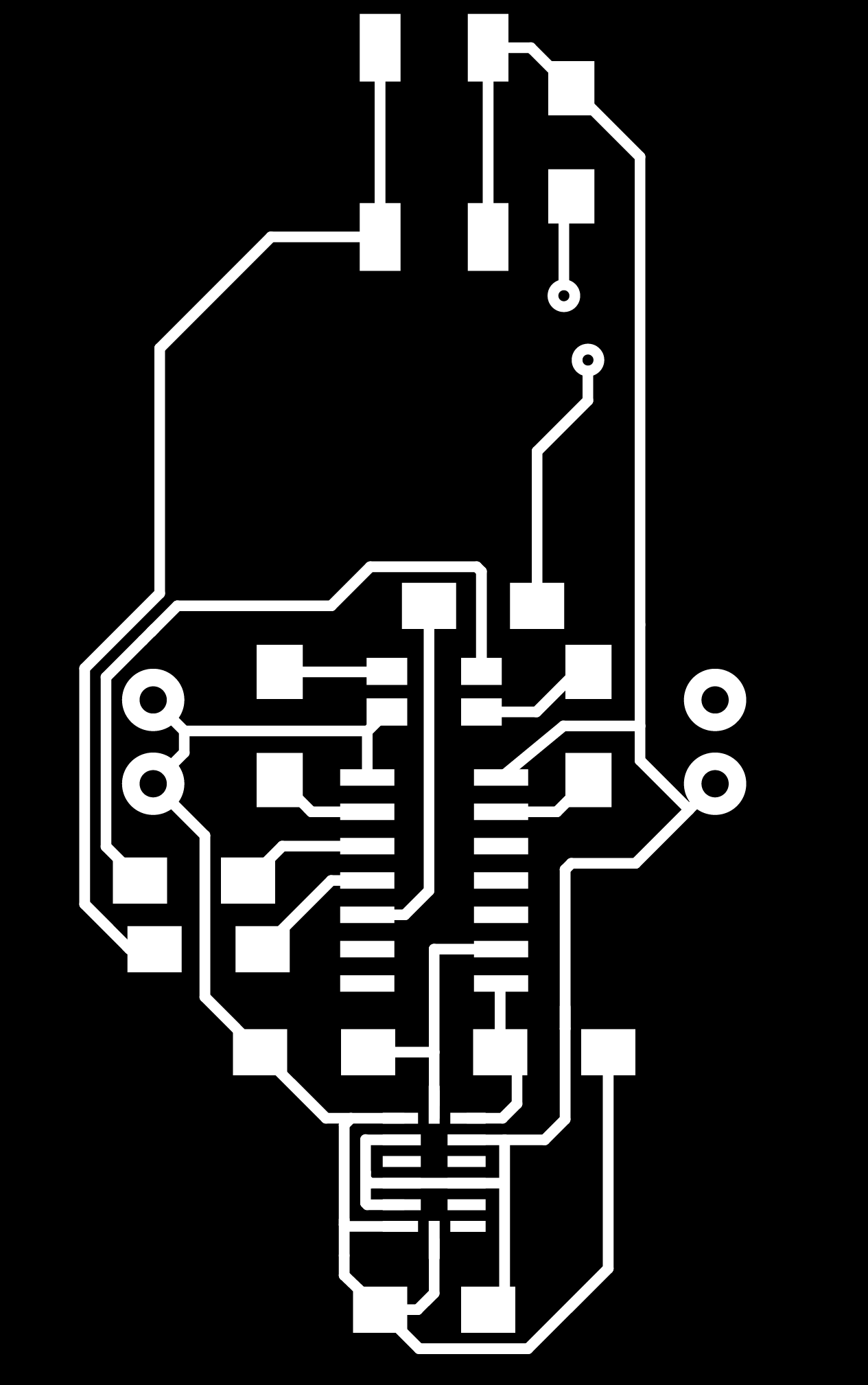
- Traces

The exports from KiCad needed some cleaning up in Illustrator of lines and vector points to get it looking clean and tidy.
- Holes
To get the correct diameter the image needed to be mostly white (a little different from normal), as Mods would drill to the outside of the black shapes.
- Interior Cut out
Soldering
This went well, (until, see below). Soldering the 3 axis accelerometer was always going to be the most difficult, as I wouldn’t find out if it worked until the whole board was finished and tried programming it. The vibrating motor was little tricky, as the wires (32 AWS) were too thin for a wire stripper to shorten, so I had to be a little creative (see below).
I had a ‘little’ problem with the battery holder. I had ‘blindly’ chosen the through hole version of the surface mounted battery holder that was in the Fabacademy inventory (it was also the cheapest option). From the datasheet i could see a ‘+’ sign stamped on one tab, but assumed that the manufacturers had placed a separate ‘-’ tab/fixing somewhere else. I couldn’t find out any other information so i thought they know what they’re doing. I clearly didn’t. The negative of the battery was supposed to touch the PCB board. which wasn’t going to happen on a single sided board. So all the 4 through holes on my PCB board from the battery holder were positive, and not 2 positive and 2 negative.
I found a solution using copper foil (see below) and soldered a wire through the board and connected a negative/ground to the circuit.
Test
- Continuity
Simple continuity tests showed (‘beeped’) that all the soldering joints were electrically joined. Tracks that needed to be connected were, and no surprises on any that weren’t. The sensor was firmly fixed to the PCB board, a good sign that the solder on the sensor had fixed to the unsoldered tracks on the board. The pins on the sensor were connected in the way they should’ve been. So all good with it so far.
- Embedded programming tests
To see if the sensor was connected properly and can control the RGB LED and motor would need the ATtiny1614 programmed. See Embedded Programming
Power consumption
Using a Tenmet power bench , I set the output voltage to 3 volts and 300ma current. I thought that it should be plenty for what the board would be asking for (as a comparison, USB 3.0 gives 5 volts and up to 0.9A). When my working board with a working program (RGB LEDs light individually and then the vibration motor) was setup I turned on the ‘on/off’ output button (not the machine’s on off button) to see how much current the board was actually taking.
The results for the individual LEDs came showed it drew between 8-9 mA of current, but the surprise was the motor took 35 mA by itself.
As the standard 2032 button battery was rated at 210 mAH (milliamp hours), constant use of the motor would limit the life of the battery to 6 hours. So something to consider when programming.
Power = Voltage * Current
0.105 W = 3 v * 0.035 ma (power drain per second when the motor is used.)

0.081 W = 3 v * 0.009 ma (power drain per second when a LED is used.)
What I should’ve done
Double sided PCB board
By placing a battery and its holder on the underside of the board, it was an option to mill a double sided PCB. This would’ve been the more sophisticated option (especially if there was more of the circuit on the bottom side.), but my solution worked equally as well in this case.
Design the circuit based on the power source
Looking back it might have been a good idea to also try and design the circuit based on the specifications of the proposed power source. This might have shown up some future issues and meant some adjustments/alternatives components could be made before production.
Mistakes & Issues
Battery Holder

I chose this battery holder as it was the through hole version of what was in the FabAcademy inventory. Looking at the data sheet (see above) it only gave 2 pages of dimensions. Handy for designing the footprint, but no indication of how to use it.
This problem became apparent when I was about to solder the battery holder onto the bottom of my single copper sided PCB board. A ‘+’ sign on one tab of the holder denoted that that was where the casing connected to the positive. I then realised that the other tab didn’t have the expected ‘-’ sign, and the whole casing was connected to the positive. Which meant all 4 through hole posts were actually positive and i had no way of getting contact with the negative side of the battery.
The solution i came up with (and confirmed with Henk), was to cut off one of the legs and use that hole to pass a wire and connect to some copper foil stuck on the underside for the negative connection. 3 legs would give the holder enough of a fixed position to allow the changing of batteries without possible damage to the casing.
It would nice to include using the vinyl cutter into the list of skills i used in making this project, but it is for such a small piece of foil that it would be quicker to use a scalpel/Stanley knife. I cut a circle of foil with a ‘track’ sticking out long enough to reach the hole that is the negative. Sticking it down in position, I soldered a tiny piece of single core wire through the hole, attaching to the foil one side, and the track on the other side. Cutting the wire to size afterwards and filing it down so that it wouldn’t touch the battery holder (and create a short circuit) on the bottom.
On the PCB board I had to isolate the extra ‘positive’ leg connection from the rest of the traces (easy with a Stanley knife), and add a bypass wire to continue the negative connection to the rest of the board. This was fabricated from some used solder wick as i find it’s easier to work with than the less flexible single core wire.
Wires too thin for the wire stripper
The motor wires were too thin for the stripper, so I was going to have to be very gentle with something else. I was going to have to use some wire cutters very gently to strip the wires, but i noticed that there was a bit of damage on the cutting edges of the cutter where someone had tried to cut through a thick strong wire. I thought this gap might be enough to help strip the wire, so I placed the wire in the centre of this concave gap and pulled. :) it worked.
Too little current for the vibration motor
With nothing happening when i tried to testing the motor through programming, I checked continuity - fine. I directly connected the wires of the motor to the battery - fine (i had tested it before soldering it on the board so i knew it worked before).
However adding direct power to the motor with the resistor inline stopped it working. So the resistor is taking/limiting too much current or the resistor isn’t soldered properly. Reflowing of the solder to the resistor wasn’t the quick fix that i had hoped it would be. Continuity was fine, but switching to resistance check on the multimeter showed a big fat ‘1.’ - out of range, no matter what setting i put it on. So i decided to take the resistor off the board to replace it.
I had originally ‘guessed’ at the value of the resistor to put in series with the motor to limit the strength of the vibrations - 1k ohm because I was using it in other places on the board already. So I had an idea that this needs to be smaller or taken out altogether. Checking the data sheet and it read that the motor needed 80 mA or less. Using the equation ‘V/I=R’ and its other derivations, this currently worked out to 3mA. Working out the minimum resistor needed to get 80mA being 37.5 ohms. So reducing the value of the resistor by a factor of 10 should be fine. However, I tried 100 ohm, then 49 ohm and finally settled for 0 ohm :). I can’t be sure if the other problems on the board are influencing this, but 0 ohm definitely worked for the moment. Another investigation maybe in order when I’ve got the whole board working.
Blue LED not working properly
Direct power to the LED showed the blue to work, however placed after the resistor it stopped working. As above i checked the resistance, and again no reading. So a quick swap fixed it.
Resistor not reading the same once on the board
A 4.9K resistor should measure the same resistance on and off the board, so I thought. As i had so many problems with resistors above i checked all of them on the board. I found one 4.9k ohm only gave 1.7k ohm reading. Taking it off the board and testing suddenly went back to 4.9k ohm. Very strange!.
Voltage drain
Whilst testing the programming i started to get strange reactions from the board. Very confusing, due to current problems to the motor etc, I thought it maybe the power supply and swapped the battery powering it. This worked the way i expected it to, but not for long. Testing the voltage of the batteries, they were both down to 2.8v. So I decided to try a constant 3v supply to see what would happen. Everything did! (at least what I had programmed up till then). SO my thoughts were that the resistor problems were affecting the draining of voltage and current, causing the unexpected results.
Magic smoke
And then most of my hopes of finishing the project in time went up in smoke! Attaching the constant 3v power just 5 minutes later, suddenly there was a burning smell and some white smoke coming somewhere from the board. I pulled the power connections off and sighed…
Touching the components, I could feel that the 3 axis sensor was very hot - this was likely the source of the smoke and had made its way to component heaven.
With all the other issues on the board that were originally stopping the board from working, and now this. Where to start the problem diagnostics, and could I be sure that the results were only relating to the single issue i’m testing for and not a combination of other issues i’m not testing for at the time.
Continuity tests beeped everywhere. Something was very wrong, and something was now shorting the circuit. The tracks hadn’t suddenly moved in 5 minutes, so could anything now be connecting them suddenly? A visual inspection with a loupe came up with nothing connected.
So, next step, to take off components individually - check them and the tracks and see if the short is still present.
Number one candidate - the sensor. I used the heat gun to remove it, and found a nice crispy mess underneath it and the pad son the component missing. Sensor in the bin, a little flux on the tracks, and using a solder wick, I cleaned the mess off the tracks.
Since these were the smallest tracks (and hidden), i scraped around the tracks with a sharp point to be sure there was no connections, and get rid of the sooty carbon deposits on the board (just in case these were conductive). With everything looking a lot cleaner a continuity test came back ‘silent’ :).
Now to reattach a new sensor. Which, is a ‘position and hope’ that it attaches to the board properly exercise at best. Now I had the added ‘inconvenience’ of a battery holder on the back of the board making it rock easily it pressed upon.
After several frustrating attempts, the sensor stuck to the board and i hope it works. A continuity test afterwards didn’t sound any beeps so it looks like it has solved that problem. Now to find the next.
Switch bounce
Upon testing with some embedded code I discovered that the button switch would bounce and give extra signals. Erwin (our resident electronics guru), suggested not to bother messing about with a lot of code trying to solved this issue, instead go for a hardware fix by adding a small capacitor across it (~100pF?). The time it takes to charge up blocks any signals caused by the bounce in theory.
EVALUATION
Starting from a point of minimal understanding of electronics (a little above what ‘+’ and ‘-’ meant), i’ve been able to make a fully working electronic circuit design, taking inspiration (and some design parts) from other boards and designing my own. And then being able to testing it.
It would be nice to understand how some of the values of the components were decided upon in the circuits that i based my design on, but I suppose that will be part of further learning about electronics.
FURTHER DEVELOPMENT
If I was going to develop this circuit I would do the following based on the experiences of programming and testing it as a completed project:
A stronger power source - the combination of haptic motor and RGB LED draws too much current at the same time for one button cell battery. Even LED bicycle lights have 2 button cells.
Extra RGB LED’s - The brightness of the current RGB LED lacks enough light to illuminate the hole cover of the device. Additional LED’s would give a brighter source of colour and not make it look like a single point of origin.
Add an extra 100pF capacitor - to fix the button switch bounce issue, saving the need to program a fix and processing overhead for the chip.
Add more sensors - in the development cycles, more sensors would allow give more accurate ‘mood assessments’ as well as the possibilities for more functions to drive the feedback.
Addition of an LCD or OLED screen - as the complexity of the circuit and the amount of sensors increases, a screen would be beneficial to manage the functions/settings that will need to be programmed.
Shrink the electronics - not with some sci-fi ray gun, but Neil says there are smaller format components available in the FabLab inventory. This would then probably make the 3 Axis accelerometer (currently the smallest sensor) one of the biggest components on the board. Which was difficult enough to solder by hand - the only method of soldering components available in our FabLab.
FILES
| FILE | DESCRIPTION |
|---|---|
| KiCAD File | KiCAD design folder |
| Traces | PCB Tracks |
| Holes | Through holes in the PCB |
| Edge cuts | Edge cuts |