Networking and Communications
-
send a message between two projects
Creating a network between Arduinos
Jonny and I did a networking tutorial with our tutor Andrew. He showed us how to create a network between two Arduino Nanos. We used the wire.h library which which allows you to communicate between I2C/TWI devices. We used the example sketches of 'master reader' and 'slave sender' for this exercise.
Master/Secondary terminology
Historically people have used 'master' and 'slave' to indicate the relationship between devices on a network. In recent years this language has rightly been challenged for being insensitive. Many alternatives have been proposed and in our lab we shall be using the terms 'master' and 'sender'. One of the sketches we're using has old out-dated language and I hope they'll update this.
Workflow to setup the Arduino network
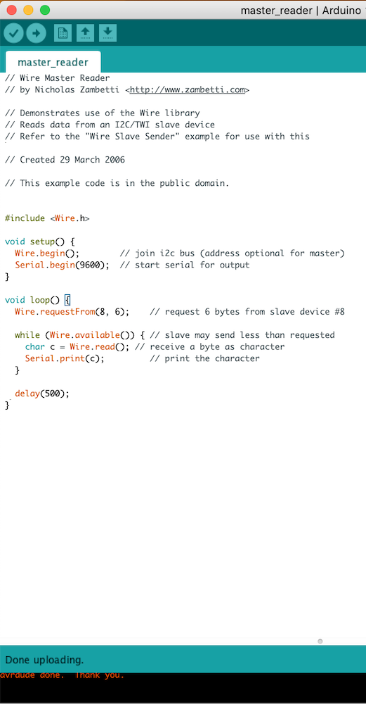
- Upload the 'master reader' sketch from the Wire library examples to one of your two boards - This is now your master board
- Upload the 'wire slave sender' sketch from the Wire library examples to your other board - This is now your sender board
- Connect your two boards together with jumper wires. You should connect GND to GND, CLK to CLK and SDA to SDA
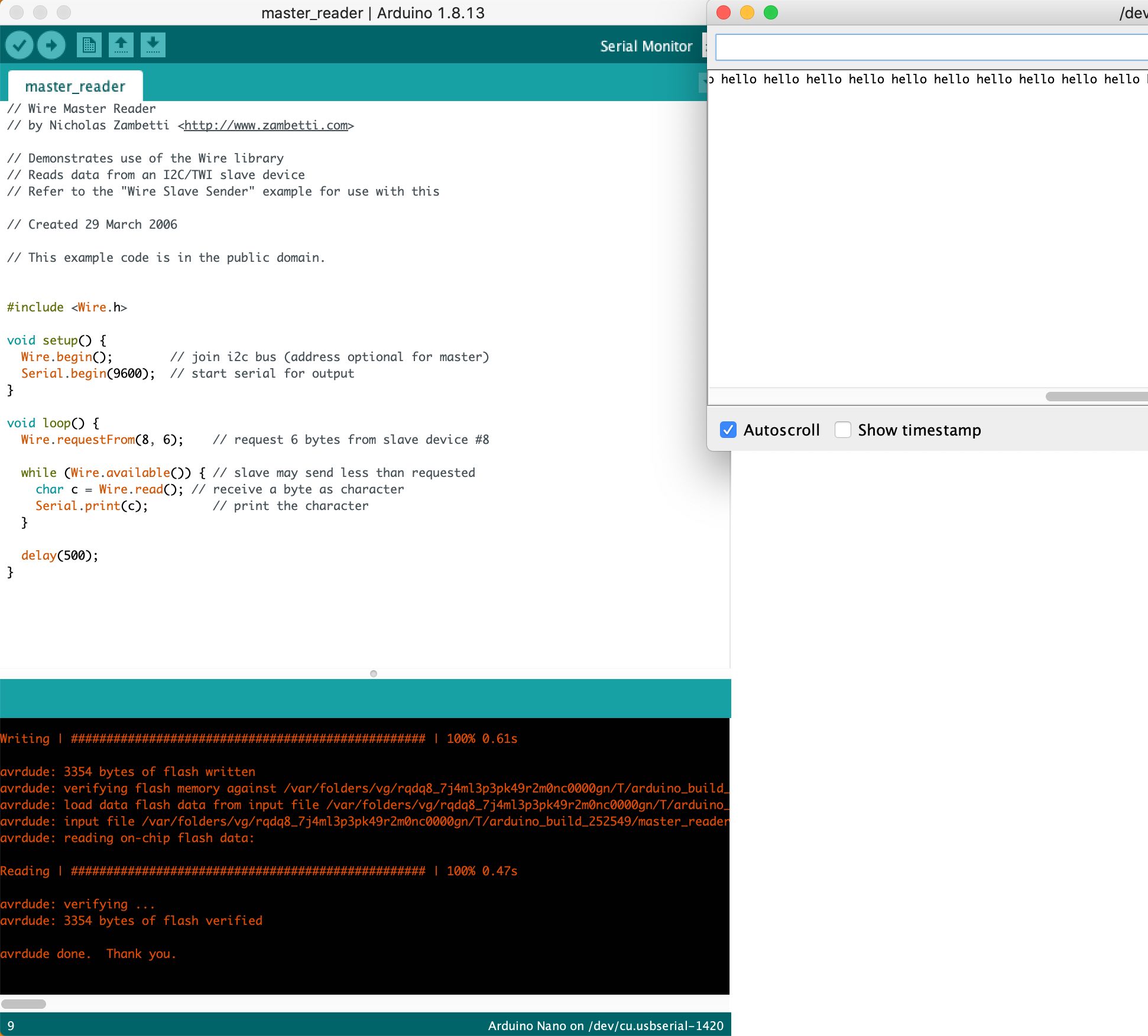
- Power up your sender board and connect your master board so that you can access the serial terminal. You should see the word 'hello' being repeately printed on your terminal
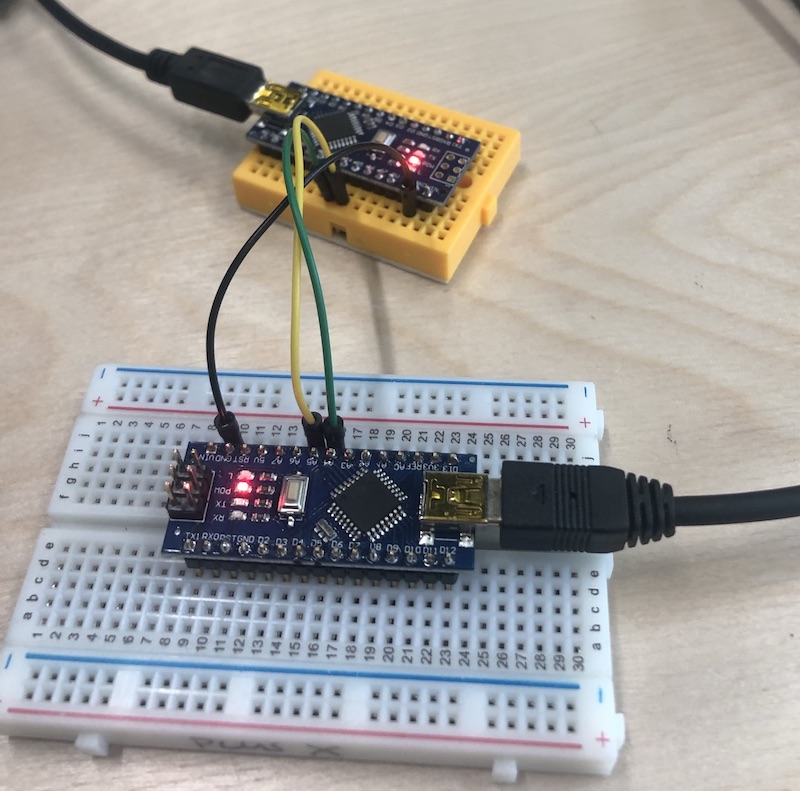
Success with Arduino Nanos
We followed the workflow above and got successful communication between our Arduino Nano boards.
Communication between our custom Fab boards
The next thing we attempted was to do make the same communication as above but using our custom fab boards. This was not so easy and we had some problems to solve.
Jonny is using a custom board with ESP32 chip. When this board is selected in the Arduino IDE, the wire.h library and its examples are not available. This was a frustrating problem because the wire.h library had simply disappeared. I checked all the root files and could see it there but it wasn't accessible in the Arduino IDE interface. Later by chance I had an Arduino Nano connected and I spotted that the wire.h library was back. The solution to this problem was to change your board to an Arduino, open the required example sketch and then re-select your correct ESP32 board from the list
Jonny's ESP32 chip has multiple pins labelled as data or clock. For example there are pins named CLK, SD0 and SD1 which are for clock and data. At the first attempt Jonny had used the wrong clock and data pins. The correct pins are named 'SCL' for clock and 'SDA' for data. On an ESP32 the clock pin is GPIO 22 and the data pin is GPIO 21
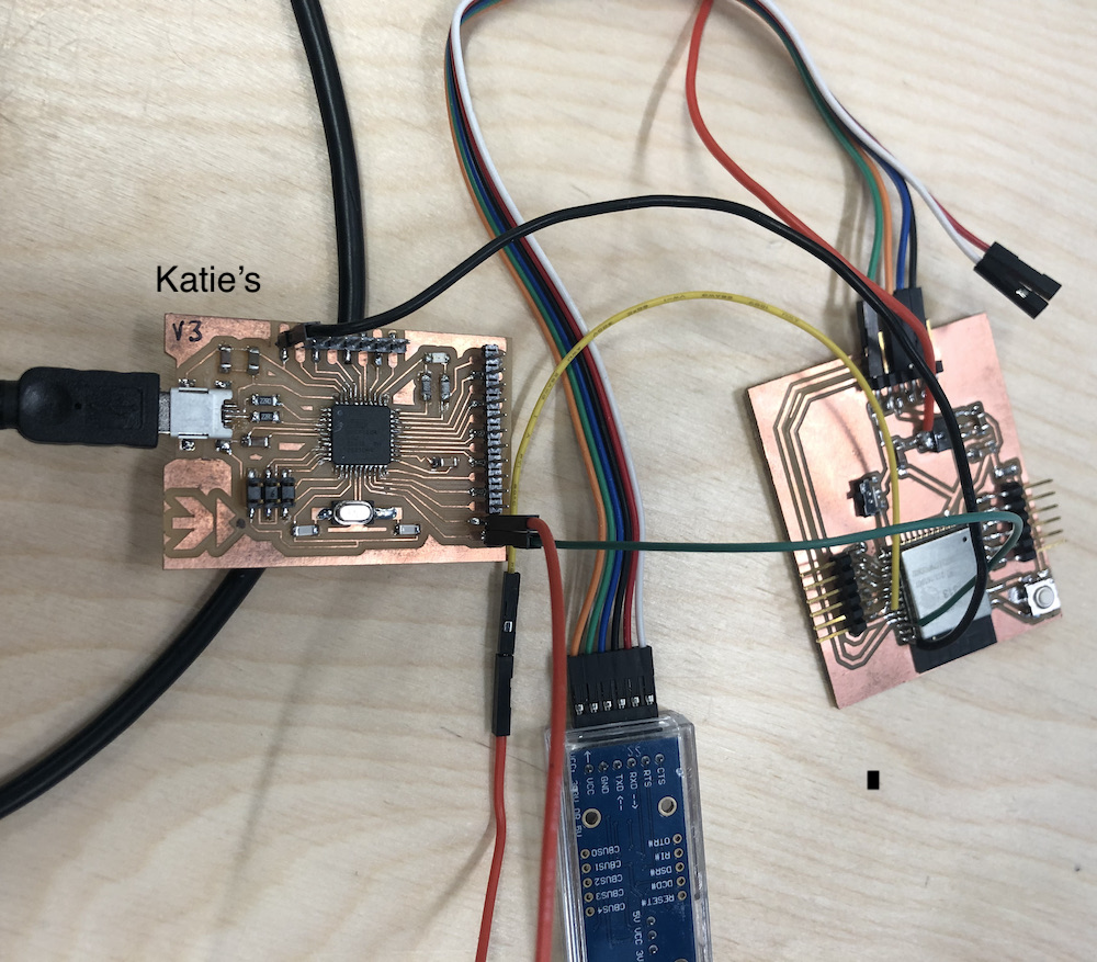
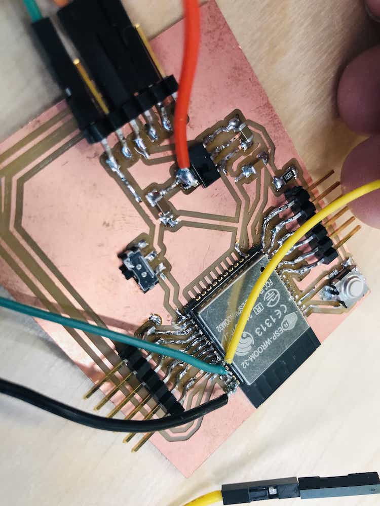
Jonny's custom board did not have a pin header attached to either GND, SDA or SCL. This was a mistake in the board design because although I had included 12 GPIO pins, I had totally forgotten to attach pin headers to VCC, GND or I2C pins. The short term solution was to solder some jumper wires directly onto the chip. This was fiddly and not a strong connection. I wouldn't be happy with this on a final project because the wire could easily become detached if you pulled on it just slightly. It did the job for today's exercise and for the future, I will update my board design to include the extra pin headers.
This photo shows the jumper wires soldered directly onto the ESP32 chip:
Finally - Successful communication between our custom Fab boards
Having resolved the issues above we managed to successfully communicate between our custom Fab boards