Input Devices
-
probe an input device’s analog levels and digital signals
Using a Multimeter and Oscilloscope
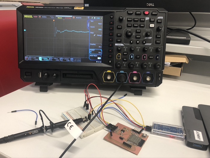
For the group assignment we decided to use the multimeter and the oscilloscope to probe our devices to see the outcome. We started this with Jonny's board as he managed to figure out how to use the oscilloscope as we had issues the last time. Here is a link to the video which we watched which helped a lot!
This is Jonny trying out the how the angle knob from our marble run would work, but for some reason this wasn't coming up on the oscilloscope.
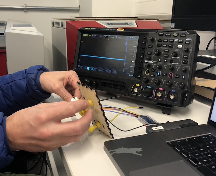
In the photo it described how you should place half the amount of voltage through the board to get the correct wave no the screen.
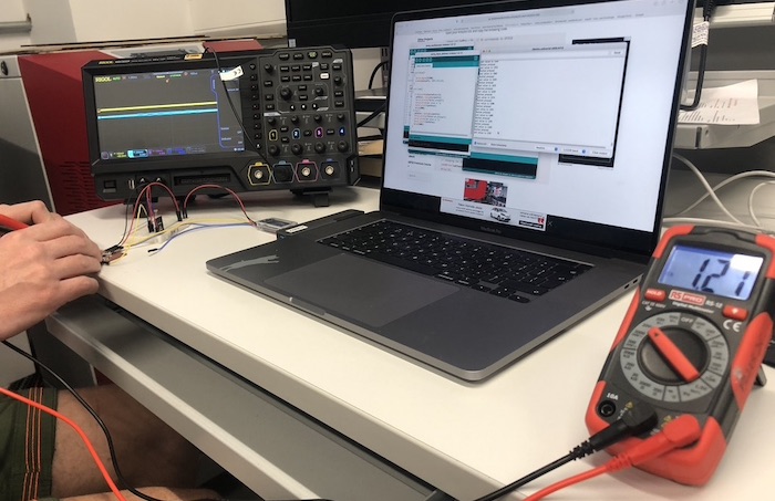
We then decided to use a photo-resistor which shows the amount of light that was coming out. It was also very interesting to see that this coursed the arduino on this computer to come up with figures such as 4000 which is showing the darkness form Jonny placing his hand over the sensor. I then got my phone and placed my light on the sensor which coursed it to go to 0. Andrew mentioned this is interesting as you can't normally get that figure with an arduino.
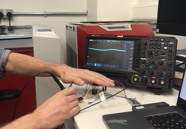
What would we would see was the wave going from the bottom of the screen to the top which is the voltage going through the component and then the time is along the bottom of the screen.
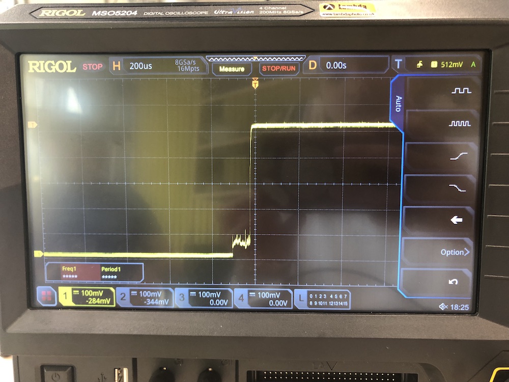
We then did the button with Jonny's board, this one was slightly different to what we thought as there wasn't as much bounce as were expecting but we think that was because in the arduino sketch there was a pull-up resistor which helps to stabilise the button so that there isn't as much bounce.
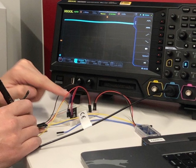
We decided to try this out again with the oscilloscope and the button circuit set up (as seen below). We used arduino and as Jonny was setting up the sketch I made the circuit by following the arduino sketch for a button (linked below).
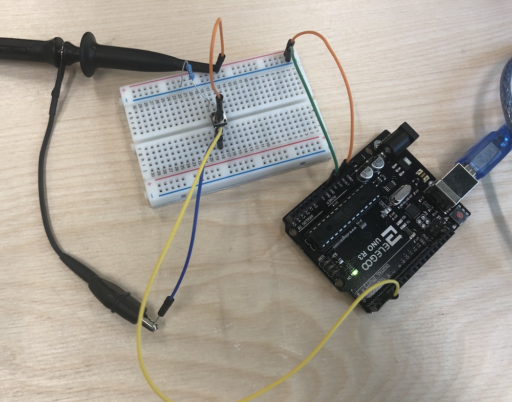
We then followed the instrustions in the manual to get the correct arrangement on the oscilloscope with the edge setting for the button. We found that by setting the direction of the edge as 'either' helped us to see what was happeing on the screen. This image is of the button that Jonny pressed and I touched the buttons to get the correct out come. By pressing 'single' meant we could get one edge rather than loads to see and understand the bouce better.
Here is the video of Jonny pressing the button for the circuit and the oscilloscope coming up with the edge that we were expecting when pressing the button down.