12. Output devices
This week I start to use several new output devices, and how to make a new board with ATtiny 412, which has powerful function and is very easy to use.
Group Assignment
We learn how to measure the output device Servo.
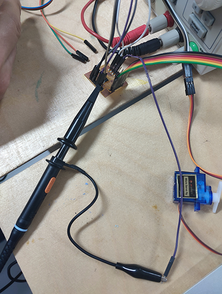
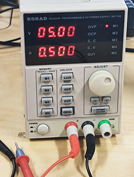
I first measure the working voltage and current of Servo. The working voltage is 5 V, working current is 0.5 A.
As the servo device is analog output device, so the PWM pattern we find is
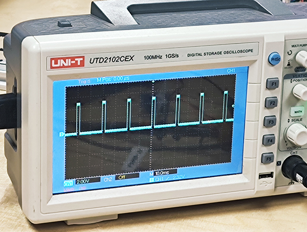
More details could be found in Chloe’s page.
Individual Assignment
Use Arduino Uno board to test LED as PWM output device
At first, I use the Arduino Uno board to test the LED output device. LED is digital output device, sometimes LED could have PWM output.
The LED in the video looks like getting lighter gradually, in fact the LED only has two states,”OFF” and “ON”. Getting lighter means the LED “ON” state stay longer than “OFF” state.
I can get a PWM LED output result by using a light sensor as one input device, the LED light changes when the light received by the light sensor changes.
In the Arduino software, both Serial Monitor and Serial Plotter can be the output devices of the Arduino Uno board. II also can get a PWM LED output result by using a capacitor touching sensor as one input device.
Use Alisauino board to test output device servo motor
Servo motor
Servo motor is an analog output device, it could rotate certain angle. We use Tower Pro Micro Servo. Its features include teflon bushing, 25 cm wire, coreless motor, servo arms and screw included. Its size is 23 * 12.2 * 29 mm, voltage ranges from 3 V to 6 V, weight is 9 g, speed is 0.12 sec/60 (4.8 V), torque is 1.8 kg-cm, working tep is -30~60 C, gears is nylon white type.

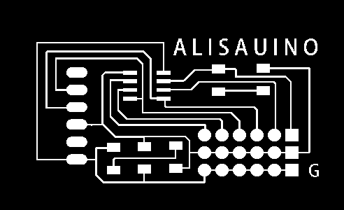
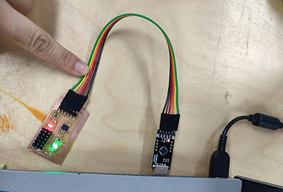
Alisauino borad The necessary componets of the board with ATtiny 412 is 1 uF capacitor, and communication components. I add one red LED connecting with VCC and GND to show the good connection of the circuit. I add one Green LED connecting with Pin 7 and GND to be one output device. To control the current going through the LEDs, add one 1000 Ohm resistor for the red LED and one 499 Ohm resistor for the greeen LED. To make sure the board is more stronger, I choose the through hole pins for communication components, and arrange VCC, GND and IC pins in 3 * 6 pins.
Test and program
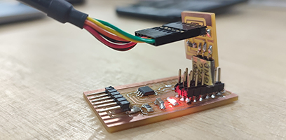
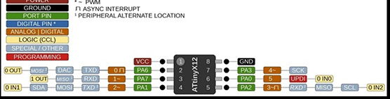
ATtiny 412 need program with UPDI each time, the pin number in Arduino are shown in the picture below.
- Test with blink code and shows the board works well.
static int index = 0;
static char chr;
static char buffer[max_buffer] = {0};

void setup() {
   Serial.swap(1);
   Serial.begin(115200);
   }

void loop() {
   if (Serial.available() > 0) {
      chr = Serial.read();
      Serial.print("hello.t412.echo: you typed \"");
      buffer[index++] = chr;
      if (index == (max_buffer-1))
         index = 0;
      Serial.print(buffer);
      Serial.println("\"");
      }
   }
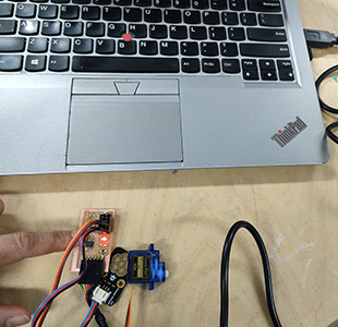
- I use the Servo motor as output device and the capacitive sensor as input device, program based on the
Example-Servo-Knotlibrary, the motor rotates when my figure gets closer to the capacitor touching sensor.
#include <Servo.h>

Servo myservo;  // create servo object to control a servo

int capacitor = 2;  // analog pin used to connect the potentiometer
int val;    // variable to read the value from the analog pin

void setup() {
  myservo.attach(4);b// attaches the servo on pin 9 to the servo object
}

void loop() {
  val = analogRead(capacitor);            // reads the value of the potentiometer (value between 0 and 1023)
  val = map(val, 0, 1023, 0, 180);     // scale it to use it with the servo (value between 0 and 180)
  myservo.write(val);                  // sets the servo position according to the scaled value
  delay(15);                           // waits for the servo to get there
}
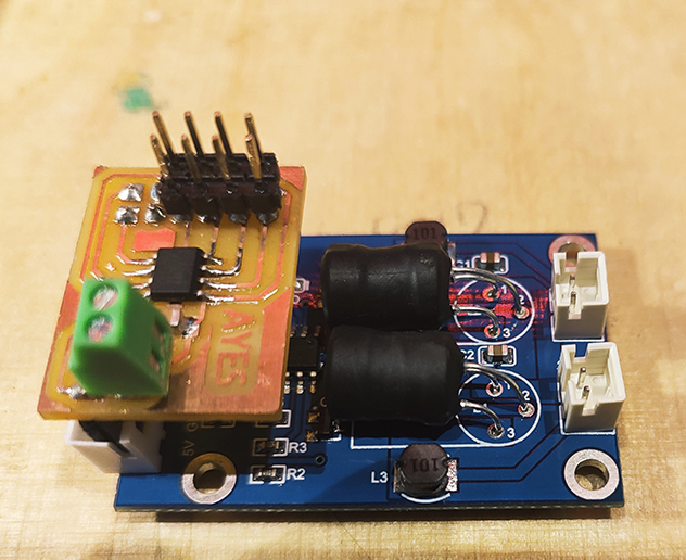
Use AYES board to test steam generator as the output device
- Use the Mist generator/steam generator as the output device, button as input device. The board I use is AYES board. The EN 2 in steam generator has two pins, GND and output pin.
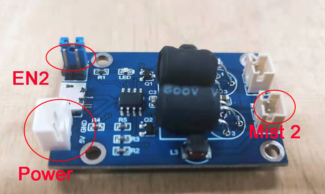
- Connecting the GND, output and VCC in the AYES board with two EN 2 pins and VCC in the steam generator, I can control the steam generator by AYES board with coding.
- When I press button, the mist release; when I press button again, the mist stop. It has two different states, the states take a turn each two button.
  int buttonstate = 0;
  int buttoncounter = 0;
  int lastbuttonstate = 0;
  const int buttonpin = 5;
  const int steamgenerator = 4;

  void setup() {
    pinMode(buttonpin,INPUT);
    pinMode(steamgenerator,OUTPUT);
    Serial.begin(9600);
  }

  void loop() {

    buttonstate = digitalRead(buttonpin);
       //if (buttonstate != lastbuttonstate){
        if (buttonstate == HIGH){
        buttoncounter++; }
      delay(50);
       lastbuttonstate = buttonstate;

     if(buttoncounter  == 2){
   digitalWrite(steamgenerator, LOW);
   delay(200);
     }  else {

    digitalWrite(steamgenerator, HIGH);
      }
    }
Reference
http://fabacademy.org/2020/labs/leon/students/adrian-torres/adrianino.html https://www.instructables.com/Capacitive-Sensing-for-Dummies/
Problems and Errors I met
- When I draw the LED output part, I connect the LED with VCC and Pin 7. After finishing soldering the board, I check the LED by the multimeter and find the Green LED don’t work. Then my instructor tell me that LED should connect with GND and VCC, while pin 7 also provide power as the VCC does. So I break the line between pin 7 and LED and connect with GND.
-
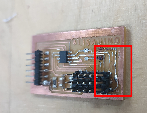
The heating time for soldering is too short that the metal don’t melt well with lots of bubbles inside and forms ugly surface. This situation may cause the bad conduction between the components and the basic copper board.
-
I burn the copper when I try to correct the direction of green LED and re-solder it. So I solder the legs of bigger LED to the board to replace the copper line.
-
We fail to use the capacitive sensor library to program my capacitive touching sensor. There is nothing printed in serial monitor.
Files
Alisauino.brd Alisauino.sch Knob.ino