10. Input Devices
Based on the hello world board, this week I am going to design a board as the input sensor for Arduino board.
Group Assignment
Compared with the hello world, the Arduino board is an existing board that can directly program. We upload program onto the microcontroller of one Arduino board, which can read digital or analog input and write digital output. The board is able to read sensor inputs, and transform inputs into outputs. For example, touching fingers as input and outputing LED on; touching nothing as input and outputting LED off.
Input device for Arduino board
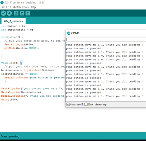
Digital read by button, digital write by LED
int button = 2;
int buttonstate = 0;

void setup() {
  Serial.begin(9600);
  pinMode(button,INPUT);
}

void loop() {
buttonstate = digitalRead(button);
if(buttonstate == HIGH){
  Serial.println("your button is pressed");
  }

Serial.print("your button gave me a ");
Serial.print(buttonstate);
Serial.println(". Thank you for reading !");
delay(50);
}
The result:
PWM output by Fade code
int led = 9;
  int brightness = 0;
  int fadeAmount = 5;

  void setup() {
        pinMode(led, OUTPUT);
  }
  void loop() {
    analogWrite(led, brightness);
    brightness = brightness + fadeAmount;
    if (brightness <= 0 || brightness >= 255) {
      fadeAmount = -fadeAmount;
    }
    delay(100);
  }
Video
Analog read by sensors, PWM write by LED. There’s no analog output except PWM. There are several pins used for PWM output in the Arduino board, they’re * 3, 5, 6, 9, 10,* 11.
int ledpin = 3;
int sensorpin = 13;
int sensorvalue = 0;
int light = 0;

void setup() {
pinMode(ledpin, INPUT);
Serial.begin(9600);
}
void loop() {
sensorvalue = analogRead(sensorpin);
light = map(sensorvalue, 0,1023,0,255);
analogWrite(ledpin,light);
Serial.print("your sensor is:");
Serial.print(sensorvalue);
Serial.print(", and your LED is:");
Serial.println(light);
delay(5);
}
Video
Individual Assignment
Light Sensor as the input device
I use a Arduino Uno to program, choose the light sensor as the input device, and LED as the output device. When I rotate the light sensor, the light received by the sensor is different, which could be shown by the LED and the value in the serial monitor.
Capacitor Touch Sensor as the input device
I use a Arduino Uno to program, choose the capacitor touch sensor as the input device, and LED as the output device.
I am interested in the capacitor touch sensor. So I read the information about the hello.load.45, but I am not sure about the function of each part of the board especially about the 2 shiled pins. Then my instructor explain the board to me and help me to understand how one capacitive sensor works.
How does the sensor work?
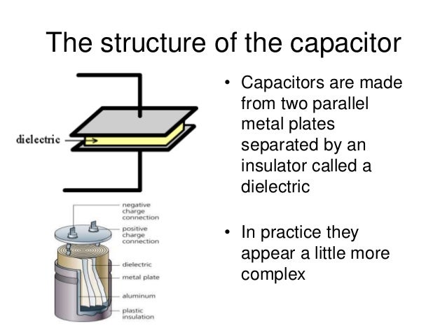
A capacitor has 2 electrical conductive surfaces ( or electrodes), one is GND, the other is connected to the positive pole of the electrical circuit. And there’s no conductive layer between 2 surfaces. The capacitor works like a small battery. If the capacitor receive a pulse, it quickly charges. If the signal goes to zero, the capacitor discharges. This create a delay in the pulse due to the time it takes to charge and discharge the capacitor.
The capacitive touching sensor works like a capacitor, the touching metal is one electrical conductive surface ( or electrode). If I put my finger on or near the sensor it creates a delay in the pulse, and this delay is recalculated by the CapSense library and generates a value you can use for triggering etc.
Reference
https://www.instructables.com/Capacitive-Sensing-for-Dummies/
Design the board
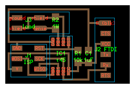
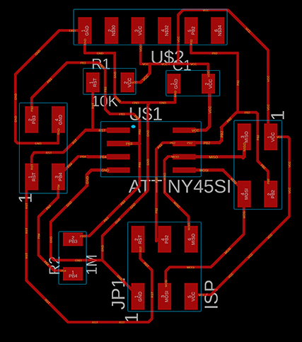
The most important component for one board is the microcontroller (IC), I choose ATtiny45. To give the board accurate 5 V , add one capacitor to keep the voltage stable. To tell the microcontroller that you have 5 V and you are on, give RST pin 5 V, use 10 K Ohm resistor to reduce the current. The communication device is FTDI and ISP. So the capacitor connects with the GND and VCC, the resistor connects with RST and VCC.
To make sure the capacitive touching sensor work, 1 M Ohm resistor and 2 piece metal is needed. The 4 pins including 2 shield,1 ground and 1 sense could be used to connect the metal. And I add two 2 * 2 pins for connecting. So the 1M Ohm resistor connects with PB3 and PB4, and the touching metal will connect with PB3 and PB4.
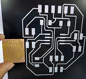
Mill and Solder
- Export the .png file from the EAGLE, the DPI 1000, monocolor.
- Use http://fabmodules.org/ to transform the .png file to the .rml film, turnning the circuit into traces of the end mills.
-
Cut the board with Roland SRM-20, tidy with valume machine.
-
Clean the board and take away the extra copper.
- Set the temperature 430 degree and solder the components into into the board. The component list:
| Component | Scale |
|---|---|
| IC | one ATtiny 45 |
| Resistor | one 10k Ohm, one 1M Ohm |
| Capacitor | one 0.2 uF |
| PINs | one 1 * 6, one 2 * 3, two 2 * 2 |
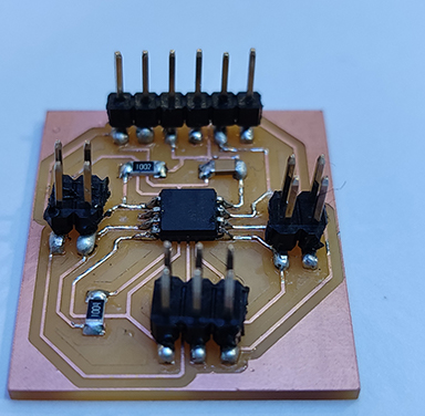
- Use the conductive tape to be one electrode surface for the capacitive touching sensor.

Test and program
-Download CapacitiveSensor04.zip, unzip to Documents/Arduino/libraries. Restart Arduino.
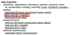
- Download the make file and .c file. Check the make file’s name should be exactly
makefile, without any extension name.
-
Open the device manager, check the connection between the usbtiny and the computer.
-
Open makefile folder in Git Bash by
cd folder site,run themakefilein the Git Bash and two new files form, hello.load.45.c.hex and hello.load.45.out.
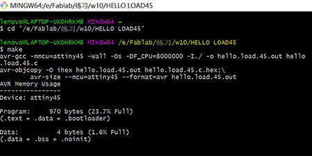
- Run
make program-usbtiny, it failed.
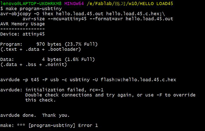
Problems and errors
-
So far the boards I made in Fablab don’t work so well during testing. And the connection between the computer and the board is bad. We check the VCC and GND circuit by multimeter according to the origin .brd file and the result shows the circuit is good. We change the PC and connection lines and the result is same. And we refold the board and test it again and nothing error is found. Finally, we decide to cut a new board and solder again. And the first trial for the second load board is bad.
-
The .png file exported from the EAGLE alway become two time larger. So the image size should be change to 50 % in PS before editing.
-
The fabmodules website couldn’t work well in Google brower in my computer. The website could open the files but couldn’t choose the mill size or calculate the traces. The Microsoft Edge failed,too. I though there’s something wrong with the picture, however the .png works well in my instructor’s Mac.

Files
Update
-
We found the ATtiny 45 microcontrollers we have are in bad state. So we change to use the ATtiny 412.
-
I design and make the board with ATtiny 412, try to update the Arduino Capacitive Sensor Library code and find the ATtiny 412 couldn’t read the code. I also don’t find the right code for ATtiny 412.
-
Later I make a ATtiny 412 board with the button as the input device.
The button as the input device
Design the board
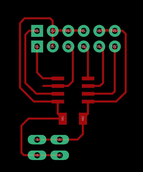
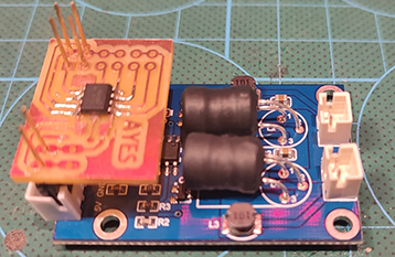
My final project is to create a humidifier and I need to one board to read the input device button and control the output device Mist generator driver. So I design the AYES board with ATtiny 412.
The components used in the AYES board
| Component | Scale | Number |
|---|---|---|
| Microcontroller | ATtiny 412 | 1 |
| Capacitor | 1 uF | 1 |
| Female Pin Header | 1 * 2 | 1 |
| Female Pin Header | 2 * 2 | 1 |
| Male Pin Header | 1 * 6 | 2 |
Considering minimum the volume of the electric parts, the AYES board shall connect with the mist driver well. The Power on the mist driver will connect with the VCC and GND on AYES board, the EN2 will connect the signal pins on AYES board, the mist 2 will connect with the mist/steam generator.
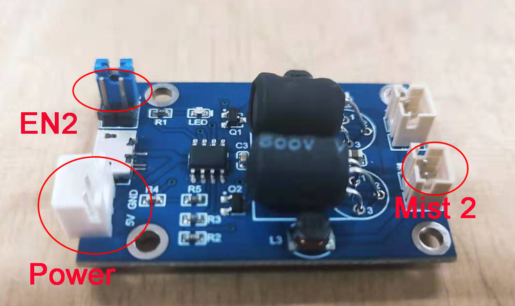
So I measure the distance between the EN 2 and Power on the mist driver and arrange the corresponding pins on my board. The EN 2 connects with GND and ATtiny PA 2 in ATtiny 412.
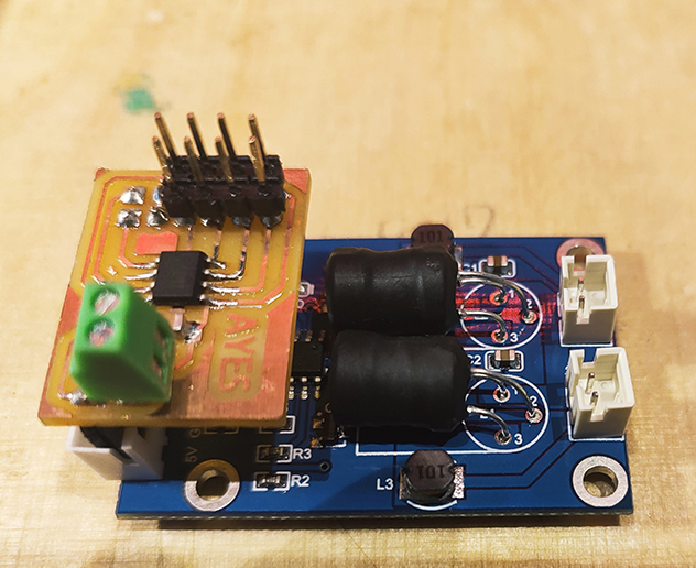
Mill and Solder
I mill the board, wash it with 75% alcohol by one old toothbrush, make sure there’s no dust and each copper wire is able to conduct the current. Then I fix the female pin headers to the bottom of the new board, and find my board is a little small so I decide to solder the pin headers after they connect with the mist driver board.
I solder all the components under the temperature of 350 degree with solder oil. The soldering process goes well after I use solder oil, especially the IC soldering process. Before soldering the micro-controller, I check the function of ATtiny 412 in case it is in bad state. Then I put lots of solder oil on the micro-controller pins, heat one copper pad 3 seconds, add a little solder quickly, continue heat the pad 2 seconds and take away the soldering iron. The AYES board I soldered this time works very well.
Test and program
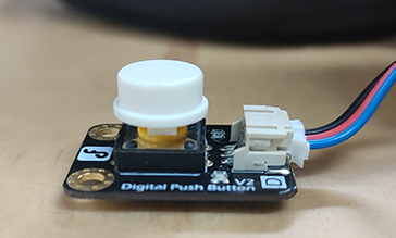
I use a button as one input device, test the board and program. The button is a digital input device, it usually has two states, “Off” and “On”. If I count the times that I press button, the times could be 0,1,2,3, 4, and so on. The times is similar with the analog input value, so I program a complicated code using the times as one input signal.
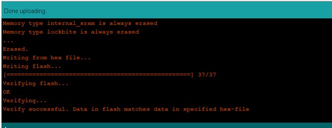
- I upload the blink codes to the AYES board with a UPDI board, it goes well.
    int buttonstate = 0;
    int lastbuttonstate = 0;
    const int buttonpin = 5;
    const int steamgenerator = 4;


    void setup() {
      pinMode(buttonpin,INPUT);

      pinMode(steamgenerator,OUTPUT);
      Serial.begin(9600);
    }

    // the loop function runs over and over again forever
    void loop() {
      buttonstate=digitalRead(buttonpin);
      Serial.println(buttonstate);
      if(buttonstate == LOW){
        digitalWrite(steamgenerator,LOW);
        } else {
        digitalWrite(steamgenerator,HIGH);
          }
      }
- Based on state change detection, I program one complicated code based on counting the times that I press button continually. Each time I press the button four times continually, the output signal will take a turn. There are four different states, including LED on and steam/mist generator on, LED on and steam generator off, LED off and steam generator on, LED off and steam generator off. The four states takes a turn each four times pressing button. However, the states changes randomly. I want to change the states in turn so I will working on it and update my progress.
int buttonstate = 0;
int buttoncounter = 0;
int lastbuttonstate = 0;
const int buttonpin = 2;
const int ledpin = 4;
const int steamgenerator = 1;

void setup() {
  pinMode(buttonpin,INPUT);
  pinMode(ledpin, OUTPUT);
  Serial.swap(1);
  Serial.begin(9600);
}

void loop() {
  buttonstate = digitalRead(buttonpin);
     if (buttonstate != lastbuttonstate){
      if (buttonstate == HIGH){
      buttoncounter++;
       Serial.println("on");
      Serial.print("number of button pushes: ");
      Serial.println(buttoncounter);
    } else {

      Serial.println("off");
      Serial.print("number of button pushes: ");    }

    delay(50); }
    lastbuttonstate = buttonstate;

   if(buttoncounter == 3 ){
  digitalWrite(steamgenerator, HIGH);
  delay(50);
  digitalWrite(steamgenerator, LOW);
  delay(20);
  analogWrite(ledpin, 180);
    }    else{

   if(buttoncounter  == 1){
 digitalWrite(steamgenerator, HIGH);
 delay(50);
 digitalWrite(ledpin, LOW);
   }  else {

  if(buttoncounter == 2){
  digitalWrite(steamgenerator, LOW);
  analogWrite(ledpin, 180);
  delay(50);

  } else {
  digitalWrite(steamgenerator, LOW);
  digitalWrite(ledpin, LOW);
  buttoncounter=0;

    }
  }
 }
}
I program the complicated code for the AYES before I receive the steam generator, so I use the buzzer to replace it and the board is Alisauino.
- I simplify the code to meet the 1st version AYES humidifier. For 1st version AYES, when I press button, the mist release; when I press button again, the mist stop. It has two different states, the states take a turn each two button.
int buttonstate = 0;
int buttoncounter = 0;
int lastbuttonstate = 0;
const int buttonpin = 5;
const int steamgenerator = 4;

void setup() {
  pinMode(buttonpin,INPUT);
  pinMode(steamgenerator,OUTPUT);
  Serial.begin(9600);
}

void loop() {

  buttonstate = digitalRead(buttonpin);
     //if (buttonstate != lastbuttonstate){
      if (buttonstate == HIGH){
      buttoncounter++; }
    delay(50);
     lastbuttonstate = buttonstate;

   if(buttoncounter  == 2){
 digitalWrite(steamgenerator, LOW);
 delay(200);
   }  else {

  digitalWrite(steamgenerator, HIGH);
    }
  }
In the Arduino software, both Serial Monitor and Serial Plotter could show the output device of the Arduino board.I can get a PWM LED output result by a capacitor sensor as input device.
Problems and errors I met
As I use the push button as the input device, the disadvantage of the button shows up. The spring in the button will bounce up and down quickly if I press it quickly, which causes a very short current and even produce several input signals, making the output on and off quickly.
My instructor suggest me to use the DE-Bouncing code to avoid the unwanted influence. I try the code shown in below and the influence doesn’t reduce.
const int steamgeneratorpin = 4; //mist attached to this pin
const int buttonPin = 5; //push button attached to this pin

int buttonState = LOW; //this variable tracks the state of the button, low if not pressed, high if pressed
int steamgeneratorstate = -1; //this variable tracks the state of the mist, negative if off, positive if on

long lastDebounceTime = 0;  // the last time the output pin was toggled
long debounceDelay = 50;    // the debounce time; increase if the output flickers

void setup() {

  //set the mode of the pins...
  pinMode(steamgeneratorpin, OUTPUT);
  pinMode(buttonPin, INPUT);

}//close void setup

void loop() {

  //sample the state of the button - is it pressed or not?
  buttonState = digitalRead(buttonPin);

  //filter out any noise by setting a time buffer
  if ( (millis() - lastDebounceTime) > debounceDelay) {

    //if the button has been pressed, lets toggle the mist from "off to on" or "on to off"
    if ( (buttonState == HIGH) && (steamgeneratorstate < 0) ) {

      digitalWrite(steamgeneratorstate, HIGH); //turn mist on
      steamgeneratorstate = -steamgeneratorstate; //now the mist is on, we need to change the state
      lastDebounceTime = millis(); //set the current time
    }
    else if ( (buttonState == HIGH) && (steamgeneratorstate > 0) ) {

      digitalWrite(steamgeneratorstate, LOW); //turn mist off
      steamgeneratorstate = -steamgeneratorstate; //now the mist is off, we need to change the state
      lastDebounceTime = millis(); //set the current time
    }

  }//close if(time buffer)

}//close void loop
Files 4_states_changing by_pressing_button.ino