Approx
Final presentation video, slide .
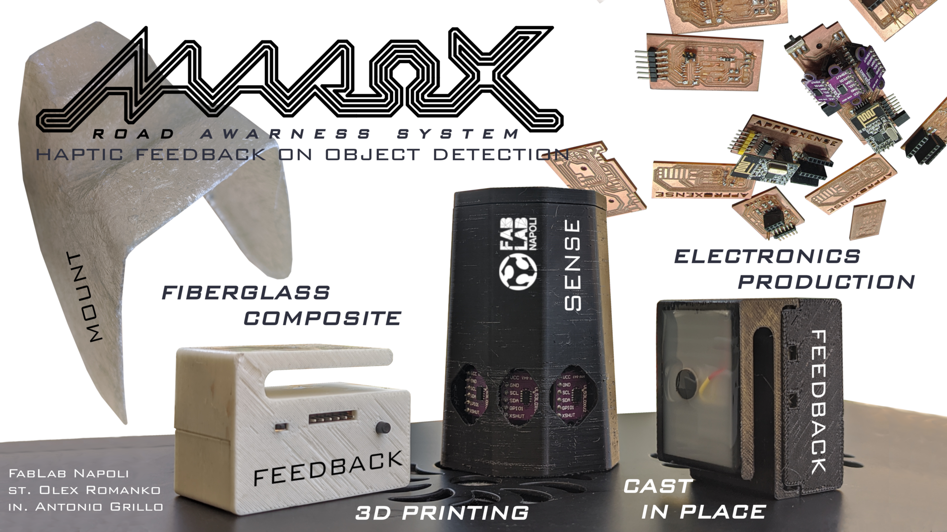
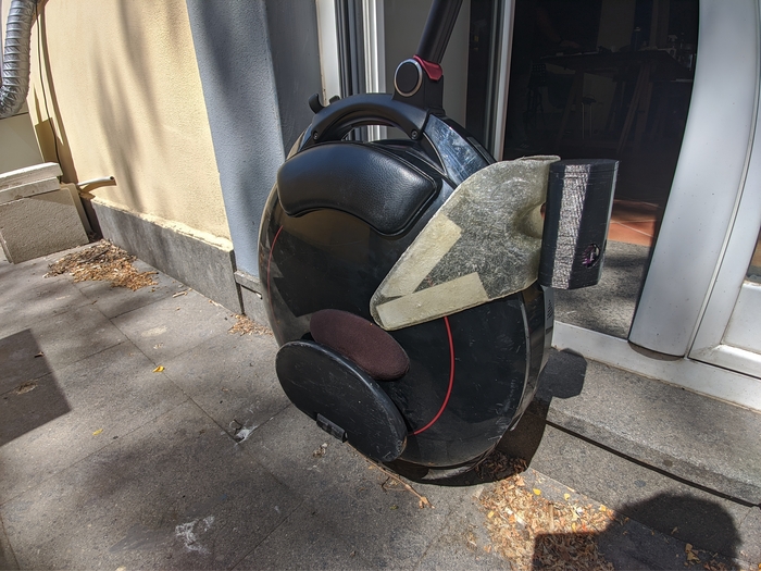
The idea is simple, using tof distance sensors make a device that would alert EUC (electric unicycle) rider if something is approaching him from behind. This kind of device could be used with other kind of vehicles and especially would be handy on those that are not equipped with rear or side mirrors.
Looking for some references I was not able to find exactly the same application I’m looking into but have found some similar systems with slightly different implementations and goals:
In the world of automotive there are some developments in using haptic feedback in steering wheel for GPS navigation and also for interaction with interfaces. Actually haptic could improve riding experience in different ways but not much of it was actually implemented.
Motorcycle industry was capable of seeing benefits of such systems and there are some developments already done in this field. Something like haptic jacket or haptic handlebars can inform you about dangers and drastically increase road awareness.
None of the above projects are implementing a portable solution for haptic road awareness. My goal is to create a proof of value of such a system and explore solutions in this field.
Previous weeks
Brief summary on accomplished in previous weeks.
Week 10 Input devices
Week 12 Output devices
Week 13 Networking and communications
Design

Electronics design
To design electronics during the course I’ve used KiCad with fab libraries and used to this software very much! It requires a bit of the time to understand where the things are and sometimes lacking some basic CAD features but to the end it’s a good tool and providing all I need and more for designing electronics.
Sensor device

Feedback device

▣ SVG Files
▣ KiCad files
Enclosure design
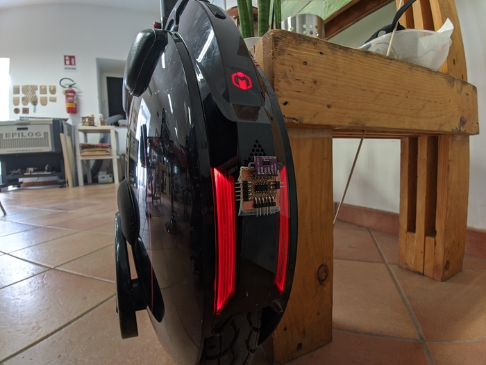
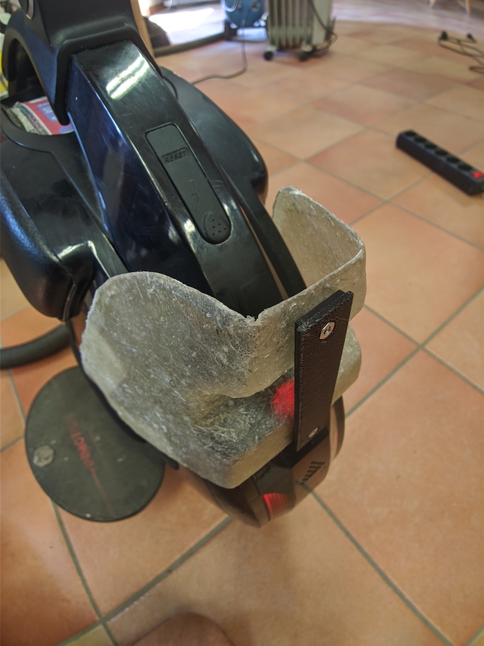
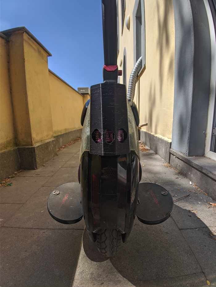
In designing process one of the main things is to define parameters that will constrain the design and start from those. In my case the device will be mounted onto EUC so I decided to scan the monowheel and use this mesh as the starting point.
Mount
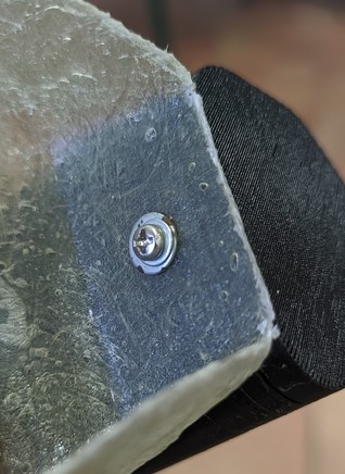
To hold the device I’ve used side surfaces geometry which are basically spherical and continued this shape into the mounting legs with great contact surface. This would allow me to simply use double adhesive tape to attach the mount.
Sense device
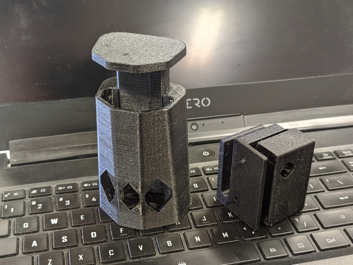
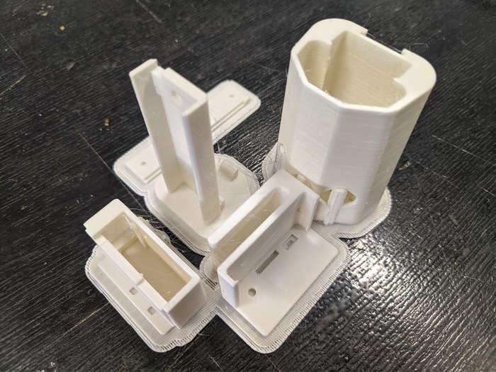
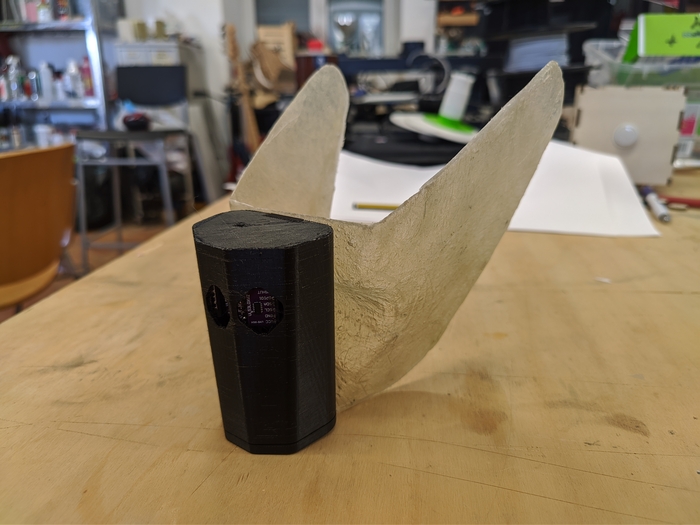
For sensors, I’ve used simple slide-penal principle to house all the components with battery also protecting them. All the electronics carried by the board which is carried by inner penal which is slides into the shell. Board is fixed using only one bolt and one nut.
Feedback device
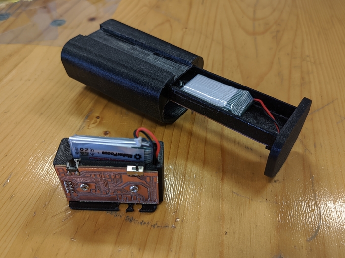
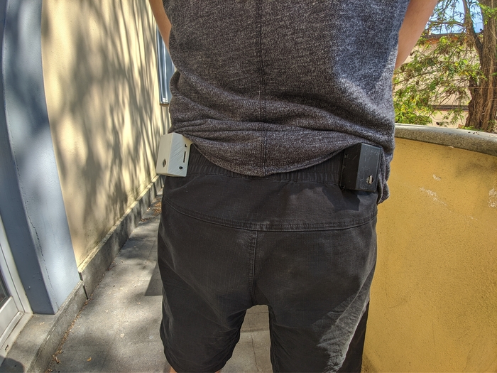
In this design I’ve used the board as a part of fitting mechanism itself. PCB is serving as the connecting piece between two printed body parts. The first part is carrying PCB battery and radio moodule while the second part is carrying only the vibration motor and serving as a belt clamp.
▣ STL Files
▼ Enclosure STL files
Manufacturing
Electronics manufacturing
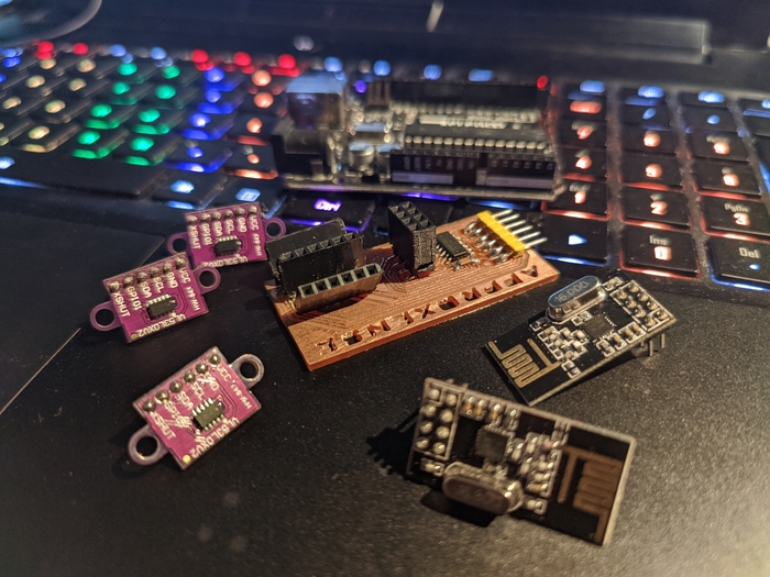
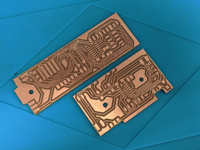
This was the roughest part required with the most iterations before it worked. Design process is tightly intertwined between the domains. One missed thing could impact the whole design chain or constrain it in different ways. But mistakes sometimes lead to better solutions! One lacking pin pushed me to iterate with splitting tasks between boards. Each time of flight sensor requires others to be shut down on the start for I2C address assigning. For this purpose XSHUT pin is used, and you need to assign separate pin for each sensor in array. It was just not enough pins for all the tof sensors and serial too, so I decided to use serial pins to send shutdown signal. This didn’t work, so I switched to use two Attiny 1614. From the beginning I was thinking on board communicating via serial is a good thing and tried to communicate between MCUs using it, but it didn’t work. Eventually I’ve switched to I2C to communicate, and it worked well and without issues.
The thing is that previous versions would work if I was simply knowing that I can use not only the pins highlighted green but also orange from the next image:
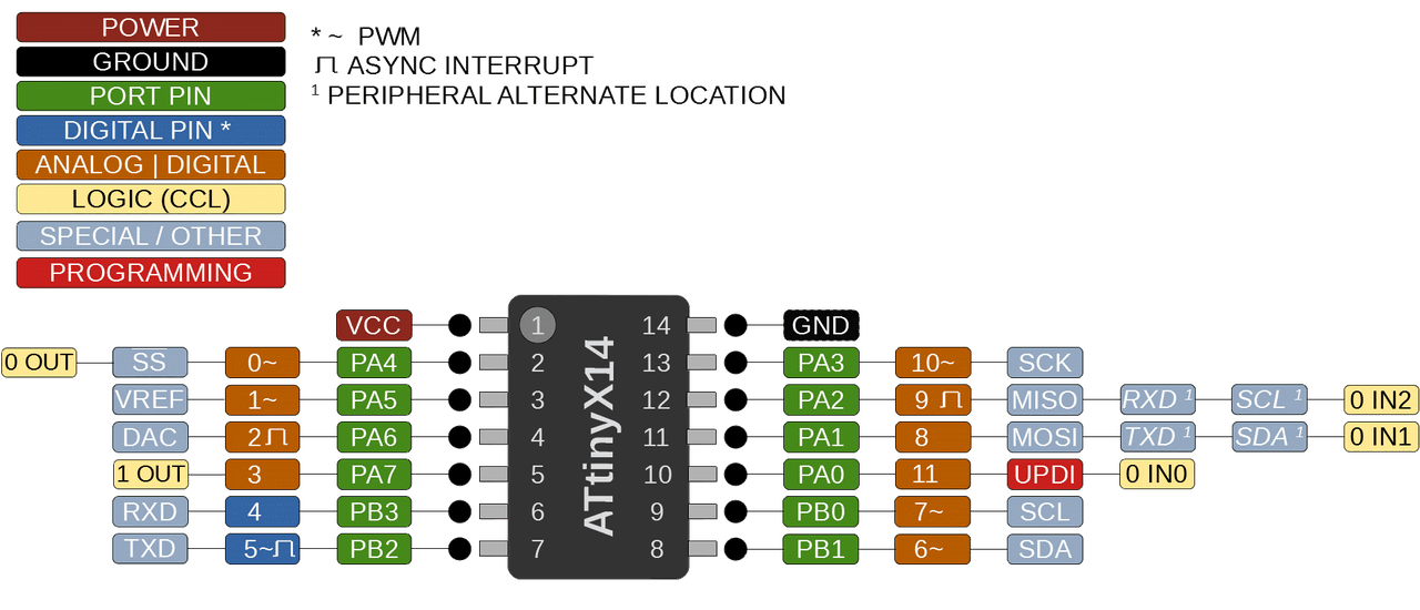
Oooops, feeling a bit silly I was nevertheless happy with the results because knowing this fact I would probably stop on the first board. Now I know that I2C is superior to serial and more convenient to use on board. Also, more constrained because of thinking I can use fewer pins that are available I’ve quite improved my KiCad routing skills. You never know if the mistake would lead to bad results!
▼ mile
▼ boards
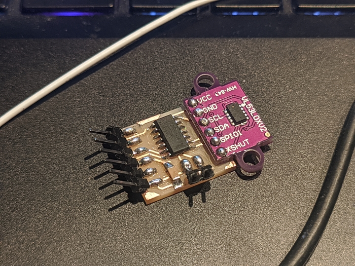
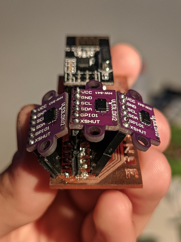
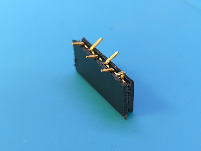
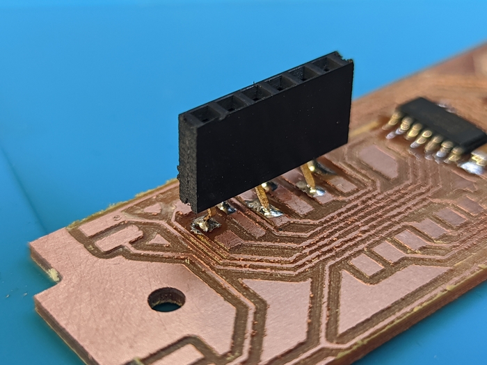
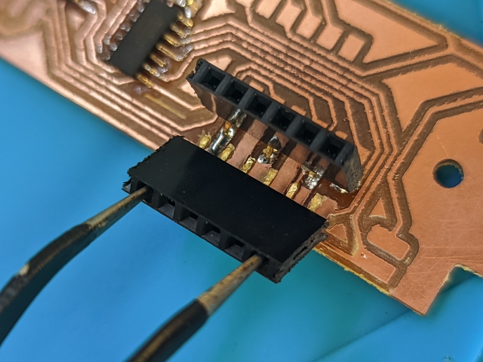
One speciall thing about sense board is the connectors for the time of flight sensors. The goal was to arrange sensors at angle to provide some “field of sensing”. I decided to use regular 1x6 pin socket with some tricky (but not to tricky) soldering.
First I’ve cut 6x1 socket and bent all the legs to same degree. Doing that is easy pressing legs against some hard flat surface. Also, you can bend 1x13 section alltogether and then cut into 1x6 (one is sacrificial) to make two 1x6 pieces equally angled.
Next, for middle connector, you should extract two legs and insert in reverse. This method allows to then put connector on pads really straightly.
▼ connector legs
▼ soldering marks
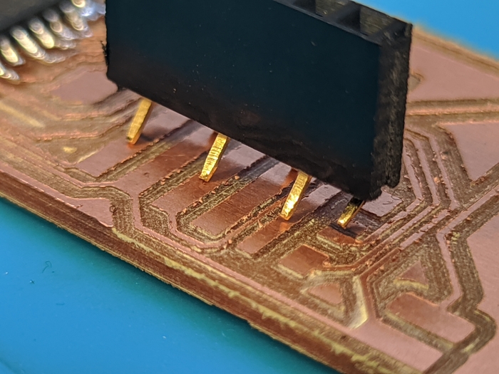
from left to right pads in order VCC GND SCL SDA XSHUT, the last leg’s are connected to different pins, so the pads are separate. As you see connector is staying aligned and stable, so the soldering would not be a problem.
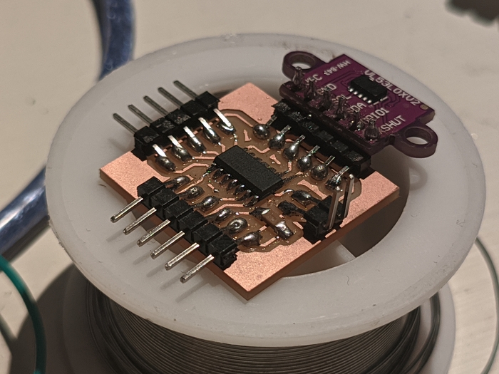
▼ soldering the middle connector
after gluing XSHUT, I’ve switched to opposite side VCC pin and then to the middle pins.
▼ attaching the left sensor
▼ tough but doable soldering
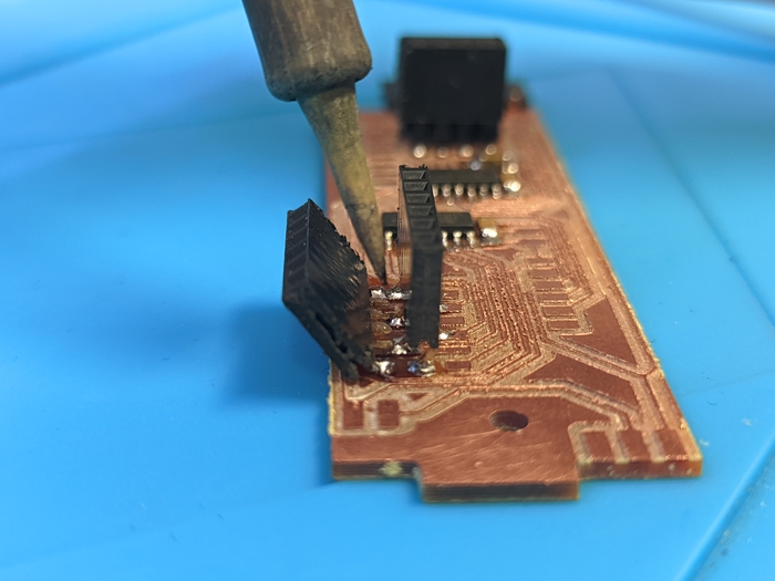
fuf, that was close…
▼ done
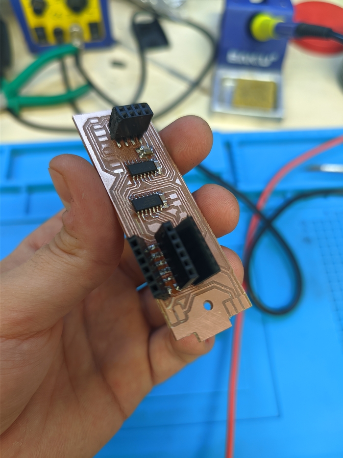
this board was badly milled, so it failed after around 6 hours of operation due to unknown reasons. Probably somewhere copper crisp is sticking I just cant see and interfering with i2c.
Enclosure manufacturing
Murphy’s law is not a law, but it’s an observation, and probably a psychological one. As the deadlines approaching humans tend to feel more stress, and it’s not the best thing for productivity. And for machines and tools every well made piece is just making a maintenance time closer. Whatever it is, I’ve experienced some of it when the terms are close and time left is tight.
To accomplish enclosures I’ve used Zortrax printer with 0.14 mm height and 60% infill. It took 3 iterations to accomplish this part.
▼ printing
▼ shell-and-clamp
The first iteration allowed me to grasp all tolerances and try the design. It came out pretty close to the final version with slight modifications.
▼ z-pla-pro
That one came out not really well, the reason is after changing the nozzle it was not calibrated so layers somewhere irregular.
Mount manufacturing
This piece was done as Week 15 assignment. Working with fiberglass was easy and quick.
▼ Casting process
you should work in gloves!
▼ Cutting off the edges
▼ resulting piece
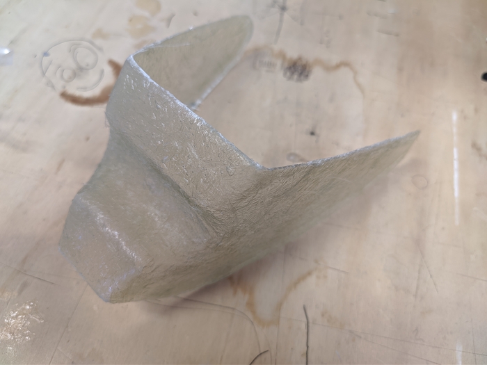
Not much questions to the resulting piece, it’s sturdy and the shape is preserved.
Arduino coding
As newbie in programming the only solution available for me is the Arduino. Using different examples and Google I was able to compile a code that is working and doing all the function.
The idea is to haptic feedback presence of the object in some “field of view” and if possibly direction where it is detected, so the feedback chain would look somehow like this:
tof sensor detecting object in range and sending the data to main via I2C
main mcu is processing the data from multiple tof sensors

main mcu is sending the data to secondary mcu via I2C

secondary mcu is sending recieved data to radio module

main radio module is transmitting one data to all secondary modules

secondary module reciveing the data and send it to mcu via SPI

mcu is reading data and deciding to feedback or not depending on mode
Sensing device
I’m using VL53L0X ranging sensor. It’s max range is 2000 mm, but if using it in long range mode it produces a lot of noise and readings are not reliable. So the real range for my application is around 1200 mm which is not impressive and probably not enough for good detection but definitely enough for the first spiral.
2 Attinys are splitting tasks in one device. One for sensing and second for radio communication.
Attiny 1614 sensor array i2c main
First Attiny is handles tof sensors reading from them via i2c, then processing the data and encodes it in to numbers from 0 to 7 representing different states or combinations of sensors that are detecting something in range:
0 : nothing detecting
1 : only left sensor detecting
2 : left and middle sensors detecting
3 : only middle sensor detecting
4 : middle and right sensors detecting
5 : only right sensor detecting
6 : all sensors detecting
7 : only left and right sensors detecting
Then it sends this number also with the value from 0 to 100 which represents the feedback value derived from range where 0 is out of range while 100 is the minimum distance possible.
Using this amazing post on Pololu forum I was able to run 3 sensors on a single i2c bus with not problems. Also it was not an issue to attach second Attiny 1614 on the same i2c line and transmit data from main to secondary.
Attiny 1614 radio transmitter i2c secondary
After reading values from first Attiny via I2C, I decided to transmit just a one unified data to any number of feedback receivers and let them react to those values not depending on different modes. For this I’ve used this amazing article on Arduino forum as code base and guide.
▣ Arduino files
Feedback devices
Attiny 1614 radio receiver
The feedback device is simply always reading from main radio module and decides to put vibration motor high depending on mode. Currently it has 3 modes that could be cycled through with button press:
mode #3: feedback when any detection is present (default mode)

mode #1: feedback when the detection is present on left or middle sensor

mode #2: feedback when the detection is present on right or middle sensor
Those modes are based on cycling a variable through states on button press with state change detection. Also two leds are lit differently to indicate modes. For the all detection mode both led are lit-up. For left or right detection mode only one led is lit-up.
▣ Arduino files
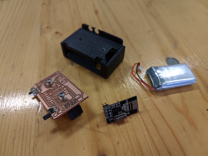
Materials and components
| name | type | value | quantity | price | vendor |
|---|---|---|---|---|---|
| vl53l0x | breakout | 3 | 21€ | Amazon | |
| PinSocket | 2.54 | 20x1 | 31 | 0.16€ | Amazon |
| Attiny1614 | ssf | 4 | 2.7€ | DigiKey | |
| Capacitor | 1206 | 1uf | 4 | 2€ | Mouser |
| nrf24l01 | breakout | 3 | 8€ | Amazon | |
| PinSocket | 2x20 | 2x4 | 3 | 2.2€ | Amazon |
| Capacitor | 1206 | 10uf | 3 | 3.33€ | Mouser |
| Capacitor | 1206 | 0.1uf | 3 | 3.9€ | Mouser |
| Resistor | 1206 | 360ohm | 4 | 0.7€ | Mouser |
| LED | green | 4 | 1.2€ | Mouser | |
| Battery | LiPo | 1000mph | 3 | 15.8€ | Amazon |
| PinHeader | 2.54 | 40x1 | 24 | 0.3€ | Amazon |
| PCB plate | copper | 70x100 | 1 | 1.5€ | Amazon |
| PetG | Z-PetG | 250g | 15.7€ | Amazon | |
| Bolts&nuts | M3 | 4mm | 3 | 0.04€ | Amazon |
TOTAL PRICE: 78.53€
System assembly
Feedback device
▼ clamp-parts
▼ clamp-parts-assemble
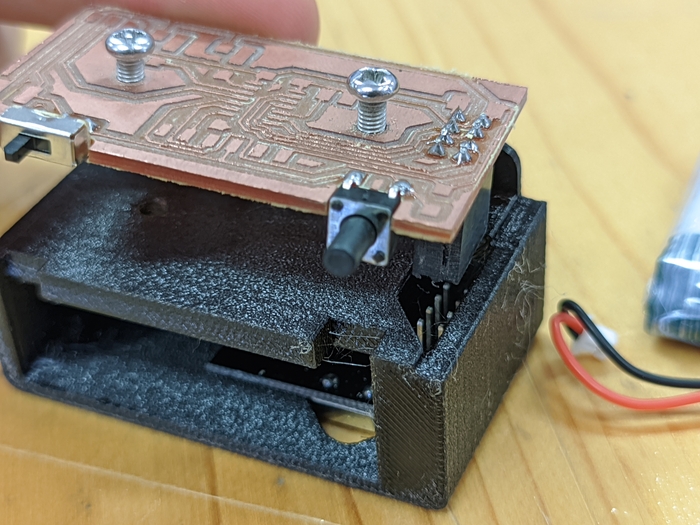
▼ clamp-parts-assemble-inside
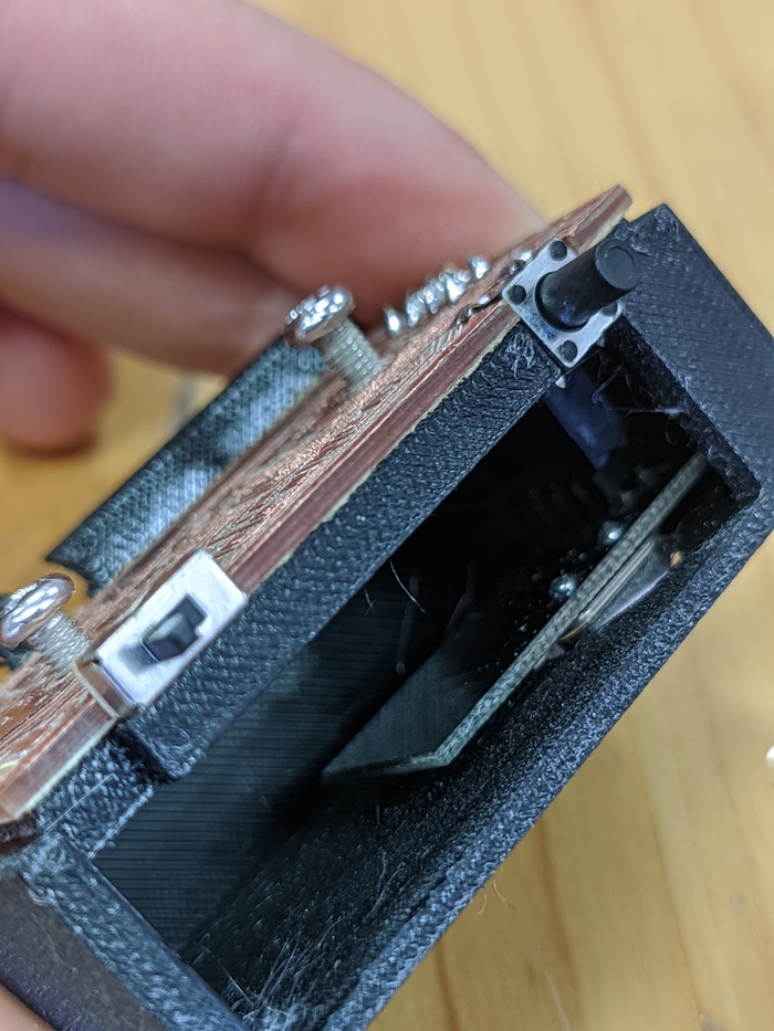
▼ clamp-parts-assemble-bat
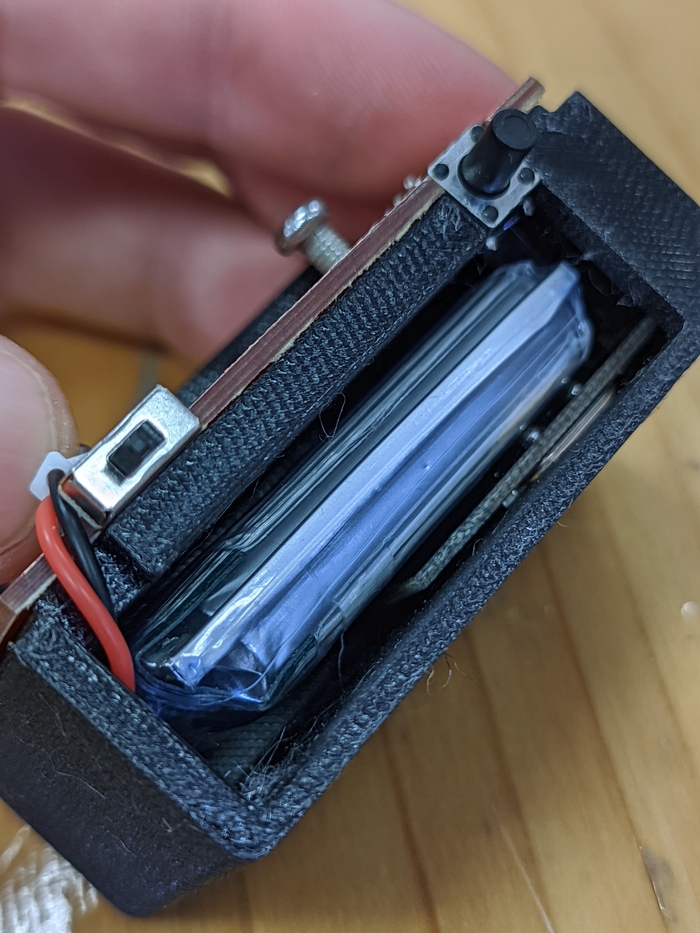
▼ clamp
Sensing device
▼ sense
▼ sense-battery
▼ sense-fit
Mounting
▼ mount-and-sense
▼ mount-bolt
▼ slide-fit
▼ slide-fitting
▼ mount
▼ rear-view
Testing
▼ Right sensor
▼ Left sensor
▼ feed-whitey
▼ feedback-setup
▼ lets-ride