Input devices
VL53L0X time-of-flight sensor
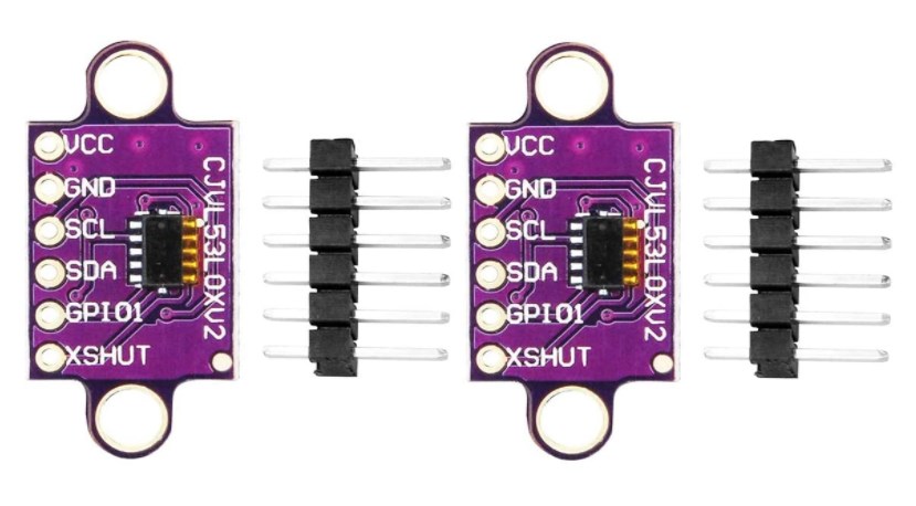
Breakout board
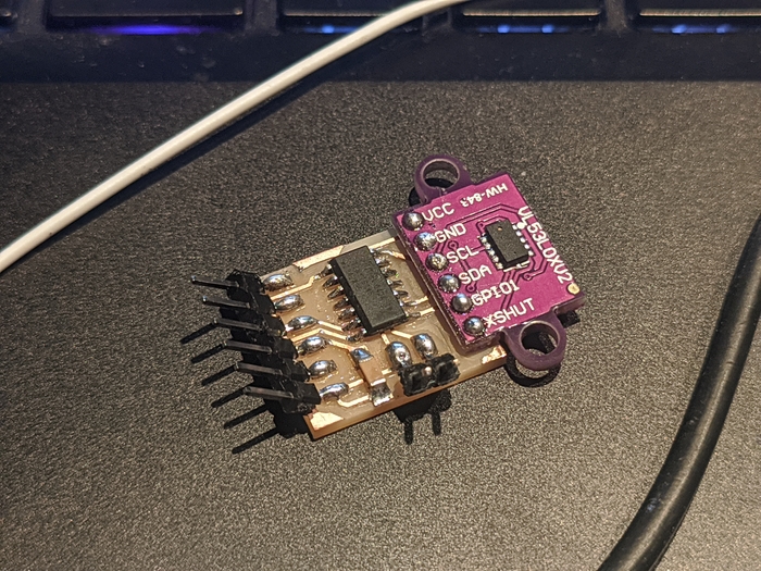
This week I was playing with VL53L0X Time-of-Fliight sensor. Those are claimed to measure absolute range up to 2m. Using breakout board should make setting-up everythng less painful for inexperienced user, so I used one that was nearly available.
▼ VL53L0X sensor
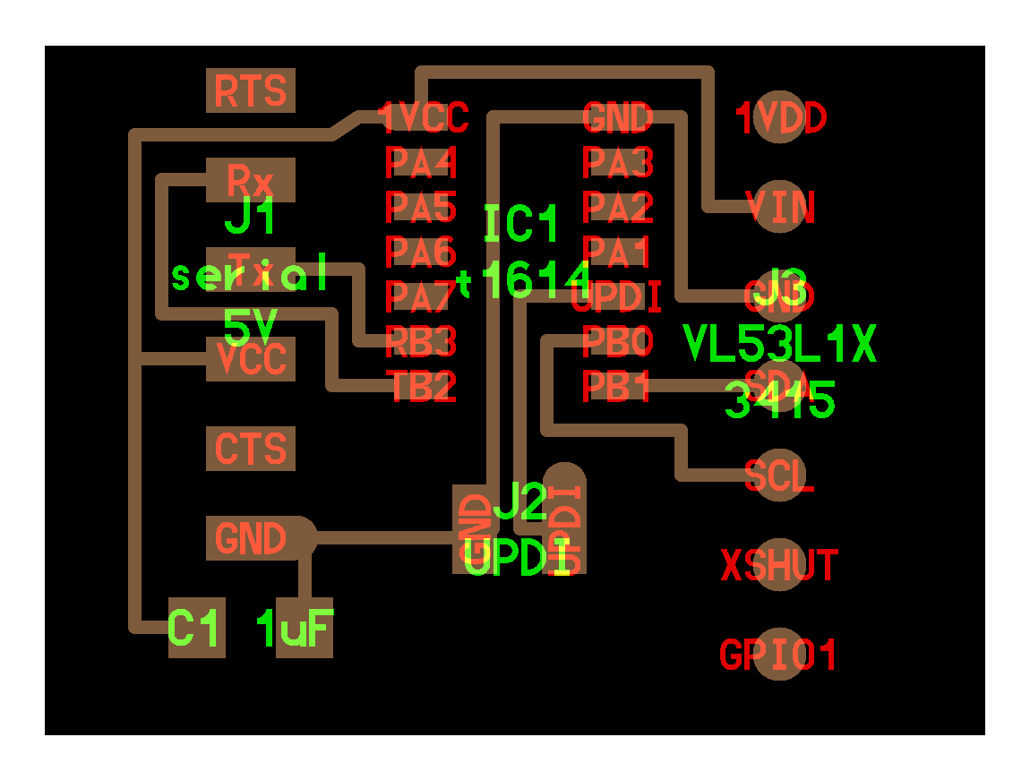
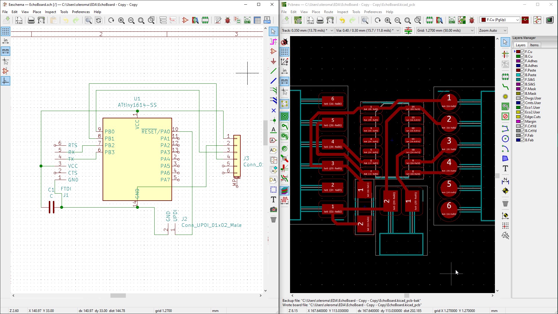
Redrawing boards in KiCkad
As a starting point the board from last week examples was chosen. Breakout board which is used there is different from I have and goes with the VL53L1X sensor. Using it as a reference I designed the new board in KiCad trying to keep pin-to-pin relations.
▼ The board
▣ Board design file
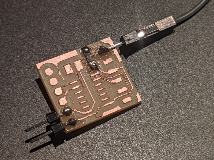
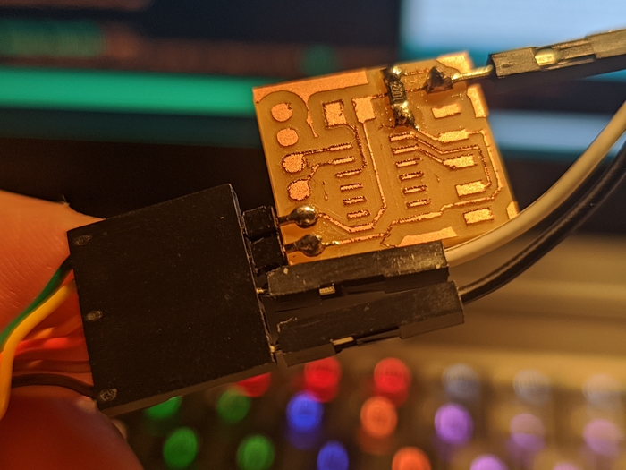
Soldering
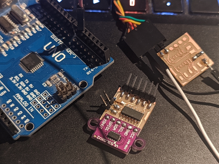
Needed components besides the main board are:
◆ ATtiny 1614 micro controller ◆ DaFuRui VL53L0X Time-of-Flight Distance Sensor ◆ 1㎌ capacitor ◆ some connectors
▼ The components
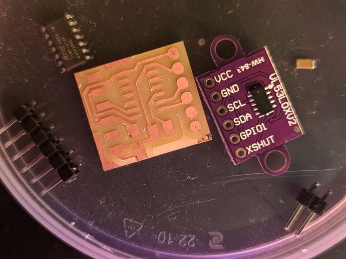
▼ The result
Here I’m using Neil’s trick to mount a breakout as SMD.
Programming
jtag2updi
Equipped with several Arduinos and FTDI cable I was pretty sure I should be able to flash the “new” ATtiny 1614 somehow. The first solution came was the jtag2updi which is the firmware for Arduino that is using “the jtag Mk2 protocol via a serial link” to bridge between AVRDUDE and updi target. It is possible to use it from Arduino IDE as well as from AVRDUDE directly. Now, looking into GitHub’s README I’m understanding that I have no 4k7 resistor which should be used between Arduino and target. It shouldn’t work, but maybe it’s worth trying without resistor.
▼ jtag2updi “bad” wiring
And you know what? It worked! Having no idea about consequences of this approach and the purpose of missed resistor I was happy having everything working. Flashing Neil’s ATtiny 1614 echo code worked as the examples from VL53L0X’s library even without changing a line from the source.
▼ Flashing the echo code and then sensor’s library example
▼ Checking the communication
Extra mode
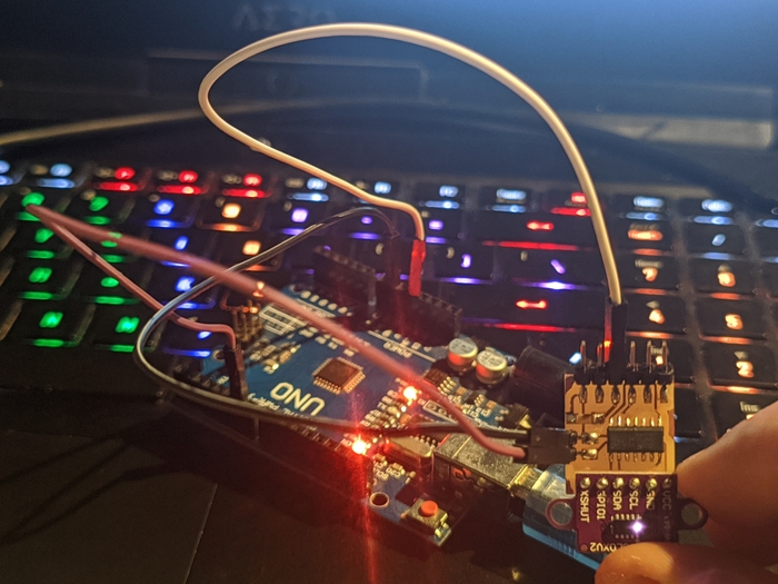
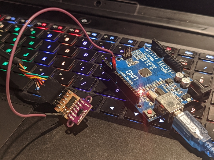
It is possible to flash the board leaving it connected to ftdi cable and using only one pin from Arduino. This allows flash and check without reconnecting anything.
▼ Flash-check setup
▼ Flashing and checking instantaneously
Here you can see the serial output from the sensor measuring a distance and then echoed serial input after flashing the new code.
Flashing using pyupdi and FTDI cable
Satisfied with the above solution for UPDI flashing I reminded that my mentor Antonio told me that I can use just a FTDI cable to program. Looking into lecture page from Embedded Programming week I found pyupdi utility and again, I was missing a component for it to work. Pyupdi requires connecting RX and TX pins using a resistor. This time I had the resistor, but it was tiny SMD and to use it the board with sufficient circuit was required. Luckilly I had some failed board attempts and there is a sufficient circuit on them! Using the same board layout as for sensor I was able to create required attachment and program with it using pyupdi.
▼ RX and TX connected for UPDI
▼ Attaching to FTDI’s RX-TX
▼ Ground and VCC attached
▼ pyupdi setup
▼ Flashing with pyupdi
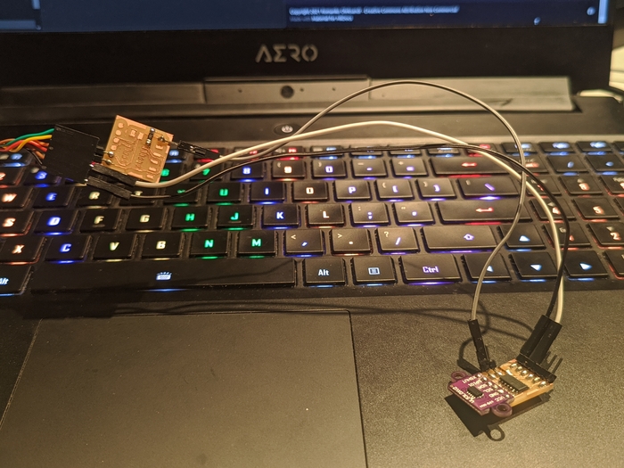
Filtering the readings
The readings from sensor are too noisy, and I’ve tried to adjust them using Exponential Moving Average method described in this tutorial.
▼ Two boards for comparison
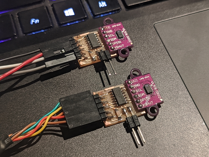
This method allows increasing readings’ stability but it also increases the time between sensor position change and actual value to be displayed.
▼ Raw readings on top and filtered on bottom
▣ Arduino files
Tweaking sensors options
Library that goes with this sensor provides some examples with some options. There are LONG_RANGE option and HIGH_SPEED vs HIGH_ACCURACY option. LONG_RANGE and HIGH_SPEED are sacrificing accuracy to achieve longer range and faster speed.
Speed vs accuracy is actually defined by sensor.setMeasurementTimingBudget(1234). As I understood, increasing the value in brackets would would increase time budget in milliseconds for processor to calculate the distance resulting in better accuracy but reducing measuring frequency.
Longer range is achieved by lowering sensor.setSignalRateLimit(0.12) and increasing laser pulse periods by sensor.setVcselPulsePeriod(VL53L0X::VcselPeriodPreRange, 18) and sensor.setVcselPulsePeriod(VL53L0X::VcselPeriodFinalRange, 14).
▼ Long range versus high accuracy
Long range allows measuring up to 2000 mm and high accuracy goes out of range after 1200 mm.
▼ High speed versus high accuracy
▣ More Arduino code 
Interfacing Genuino accelerometer with blender
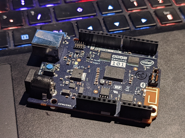
I have spotted some strange Arduino in Lab. Turns out, it’s Genuino 101 with gyroscope and accelerometer on board. It has Intel’s “Curie” module on board which provides additional capabilities to Arduino. This board is retired, but it’s working, so why not to use it.
▼ The Genuino 101 with Intel’s Curie module
▼ Applying accelerometer data to Blender‘s object rotation angles
▼ Screen recording from above