3D Scanning and Printing
This week was quite tricky to accomplish due to failed attempts to get working some opensource scanning software and obsessive idea to destroy some kind of pottery object, specifically a vase and then re-glue it back together intentionally missing some pieces. Once the object is glued and stable I want to scan it, then in some 3D software recreate the missing pieces eventually printing them and inserting inside the vase. Eventually this idea was abandoned and I switched to my final project parts to accomplish this assignment. In the next steps I’m utilizing 3D printing for my final project developments.
3D printing
The Machine
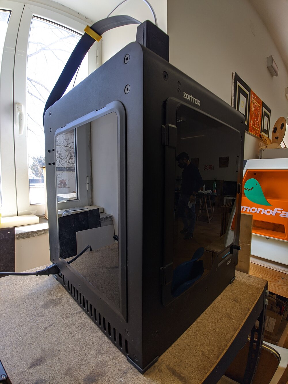
Zotrax M200
◤ Printing materials: Z-ABS, Z-ULTRAT, Z-GLASS, Z-HIPS, Z-PCABS, Z-PETG, Z-ESD, Z-ASA Pro, Z-PLA Pro ◤ Layer resolution: 90 - 390 microns ◤ Minimal wall thickness: 450 microns ◤ Build volume: 200 x 200 x 180 mm ◤ Material container: spool ◤ Nozzle diameter: 0.4 mm ◤ Maximum printing temperature 290˚ ◤ Build platform: heated (105˚) ◤ Maximum power consumption: 200 W
Printing some parts for the final project
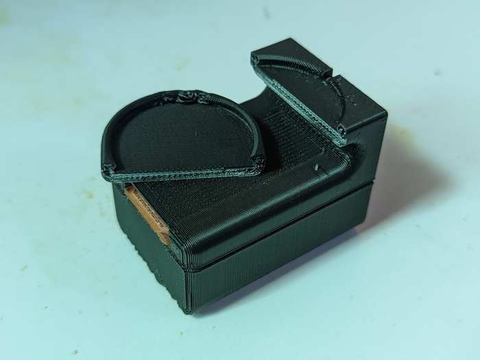
Here I’m printing one part of my final project. The piece I think is not possible to make with subtractive methods. The overall settings are defaults without supports and the printing material is Z-ABS.
Zortrax interface
▼ The default settings
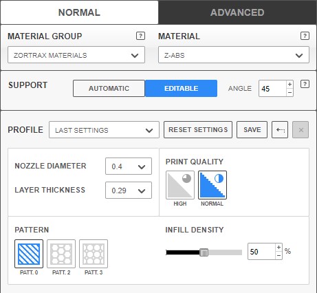
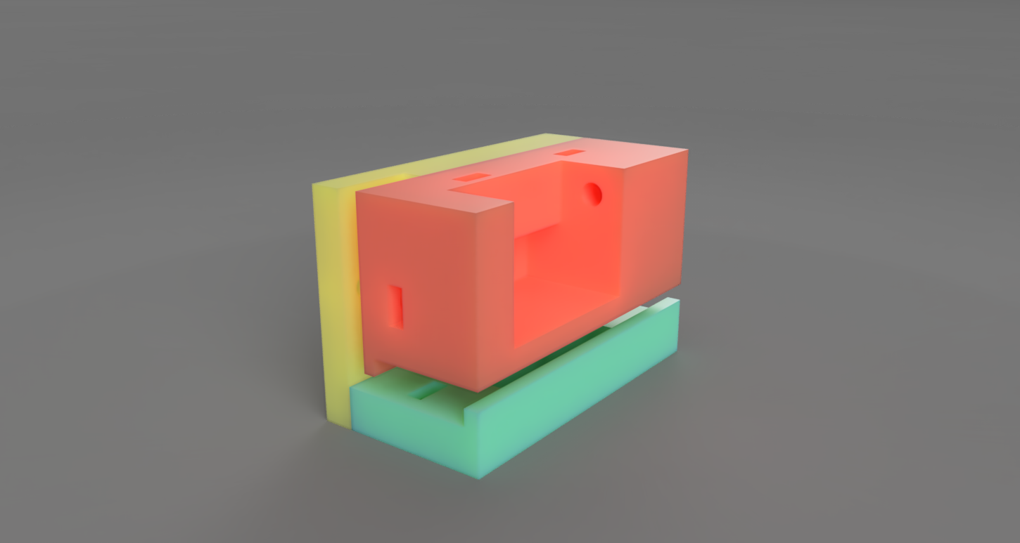
I’ve been designing a part with 3D printing design rules in mind and it should not require any supports. The “editable” Support option from the panel would allow to disregard support creation on the next steps, so I’ve chose that and proceed.
Rough print
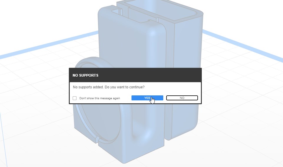
▼ Supports dialog
▼ The slicing
Rough pieces
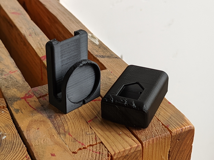
The pieces are printed and the result is OK as for the test print. Overall piece structure is present and complete with some overhanging filament that don’t influence the part performance. The overhanging spots could be managed using more dense layers or adjusting the model to get rid off the problem areas. Printing on Zortrax is easy and doesn’t require complex configuring to make solid and robust pieces.
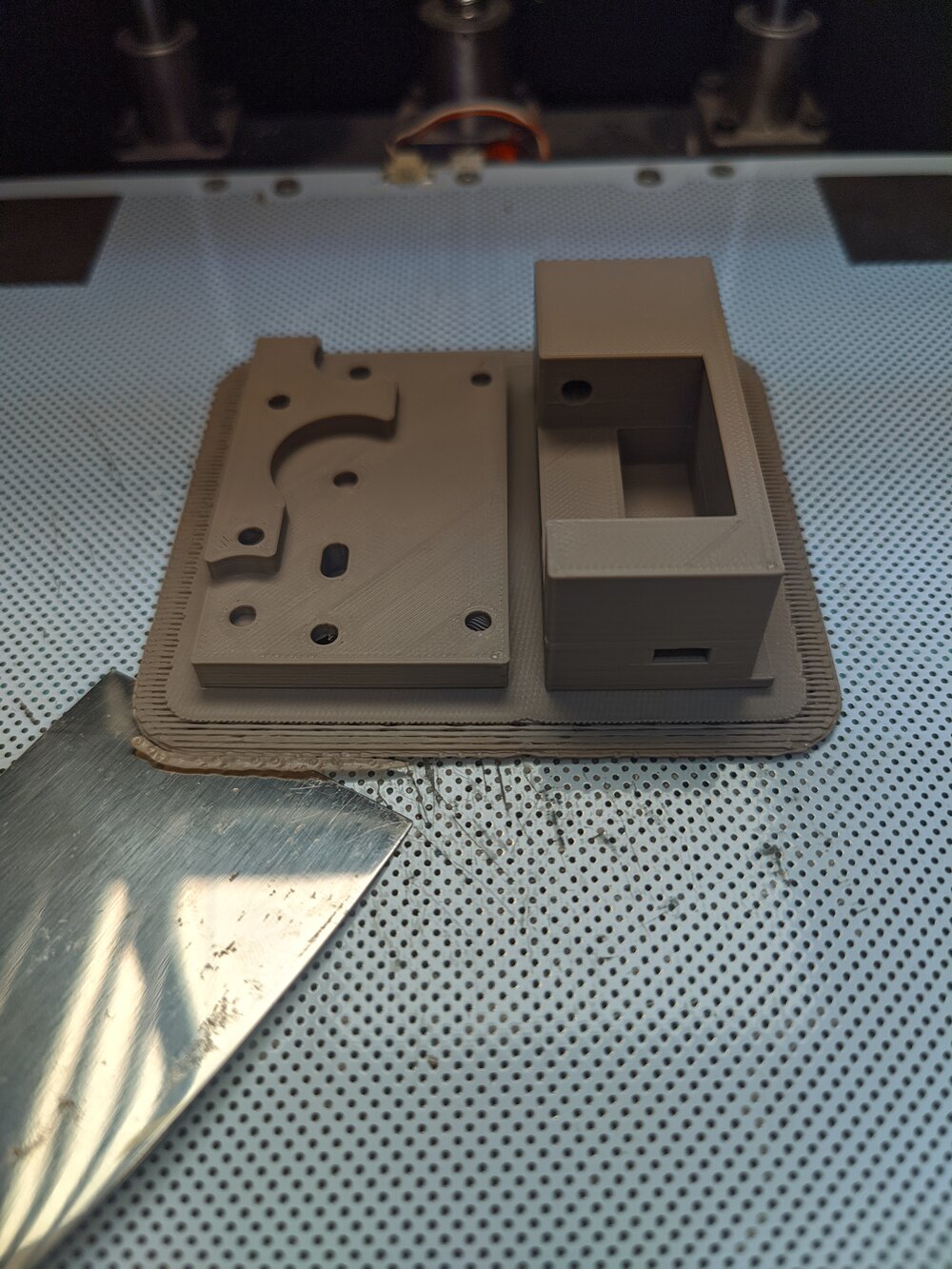
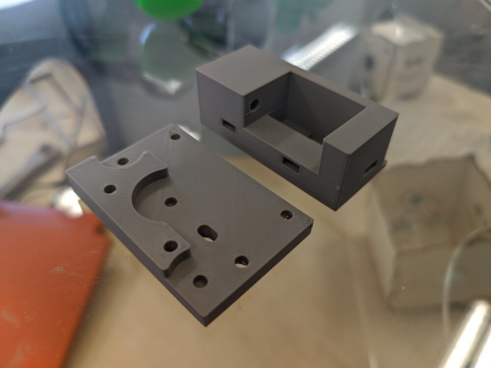
▼ Resulting pieces
Bad design and orientation
From the ground up design was wrong because the piece should be printed placed on the side so the forces that are working inside belt clip would be distributed parallelly to layers.
▼ Wrong orientation print and design
Some extra prints
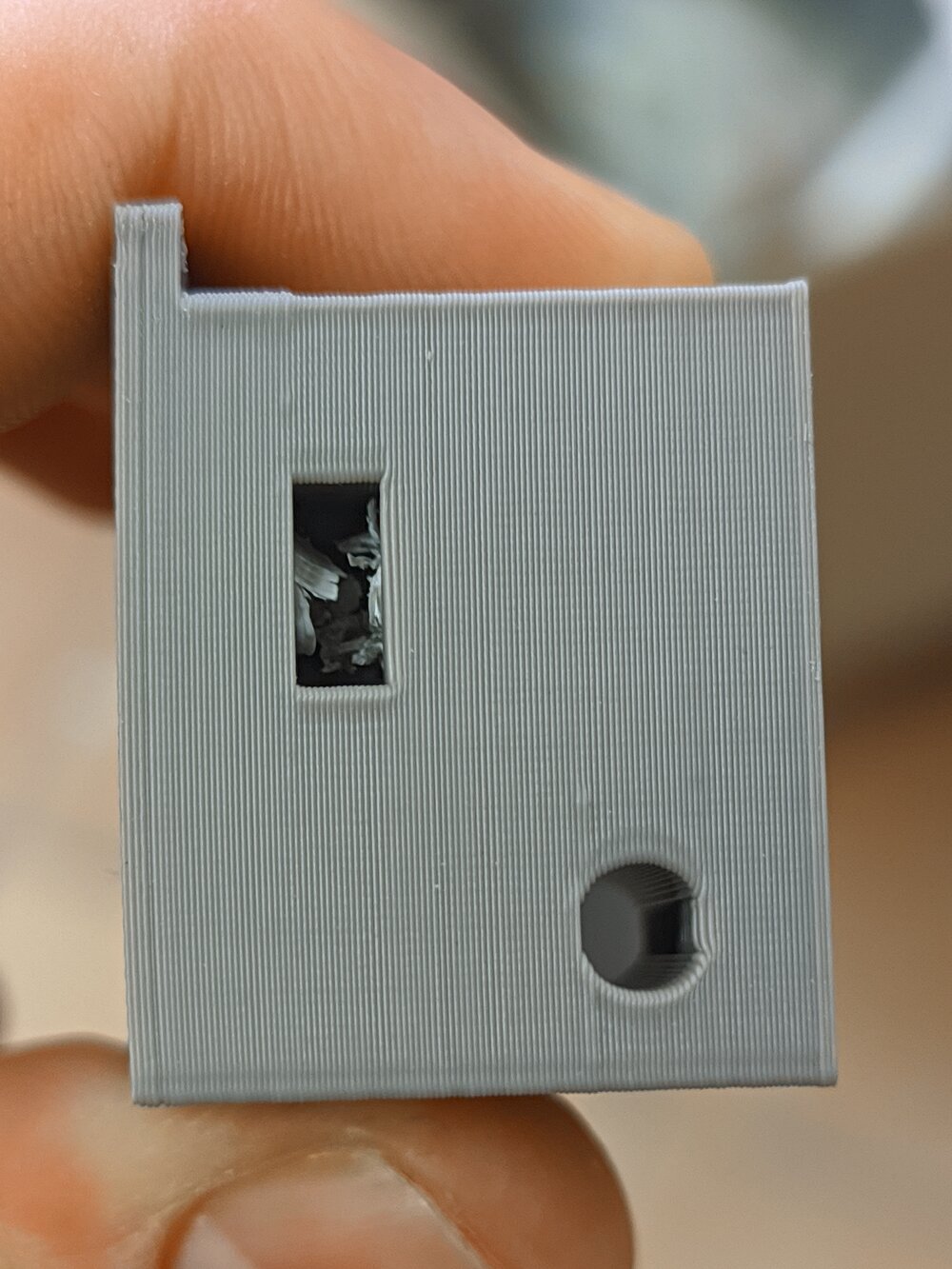
During the Fab Academy I had 3 final project ideas eventually choosing the approximation feedback device. The next piece was printed as part of my initial final project idea which is the locking mechanism that could be reprogrammed. This exact part is a physical programmer which should switch locking pin sequence.
▼
▼
▼
▼ First 2 pieces extracting
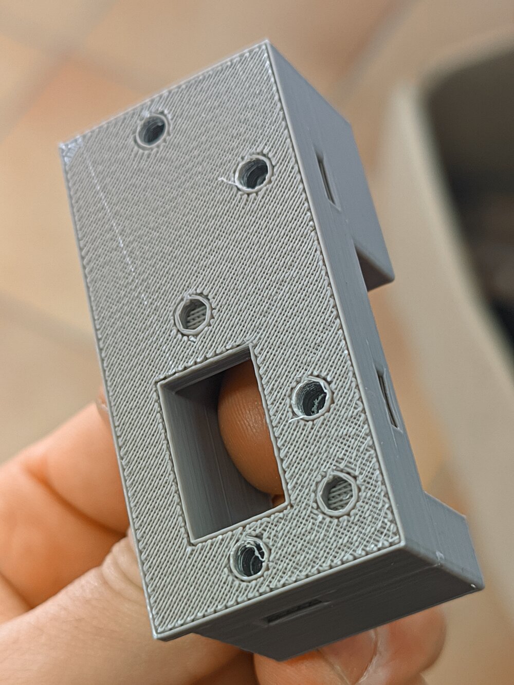
▼ The result
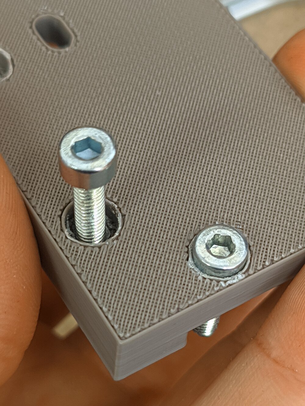
I’m satisfied with the result of the first attempt. Even that some bolt tolerances was not 100% fit I’ve been able to assemble the piece with a help of a tool.
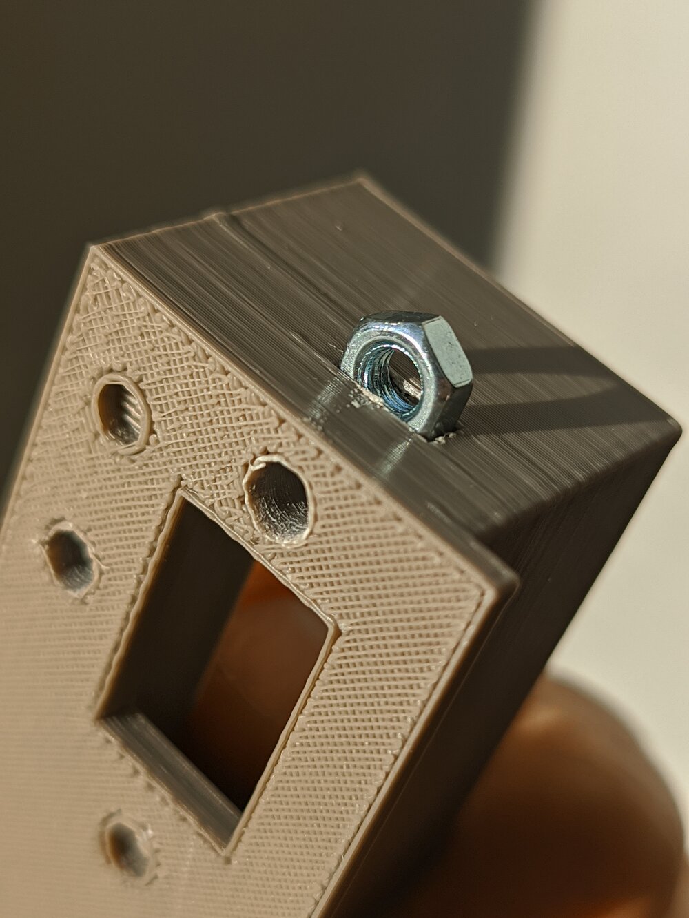
▼ Nut nest
▼ The print settings was pretty rough but nevertheless resulting part is robust just enough.
▼
▼
▼
▼
3D scanning
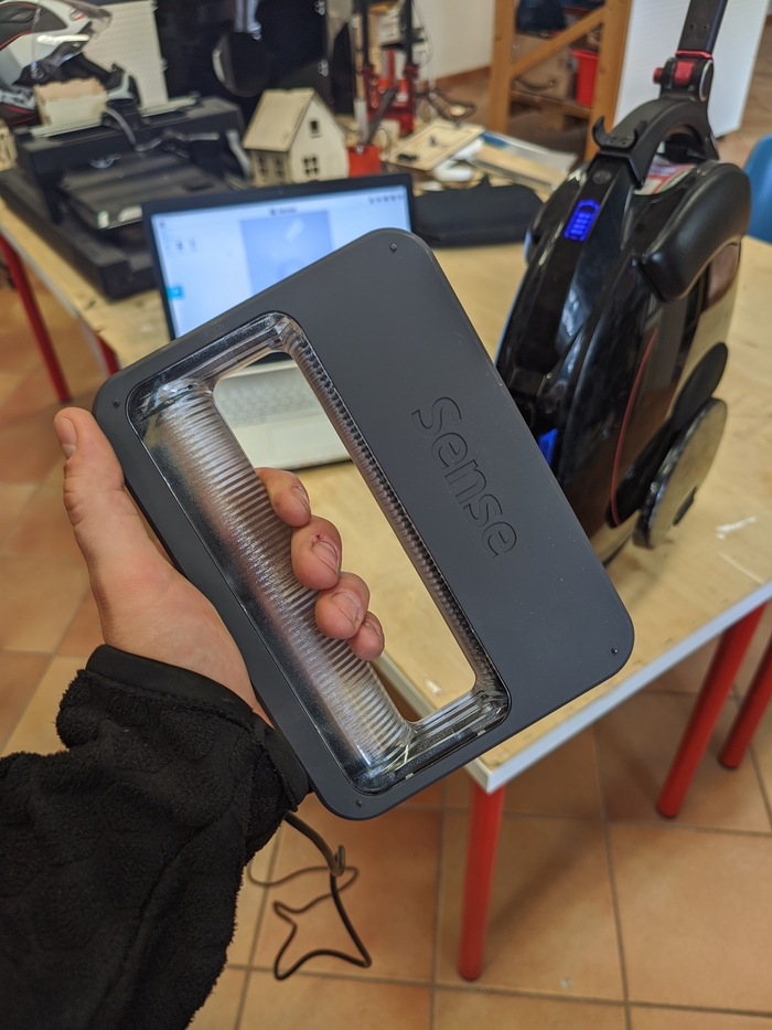
My lab is equipped with Sense 3D scanner that is very portable and able to scan object as small as 20 centimeters and up to 3 meters bounding box.
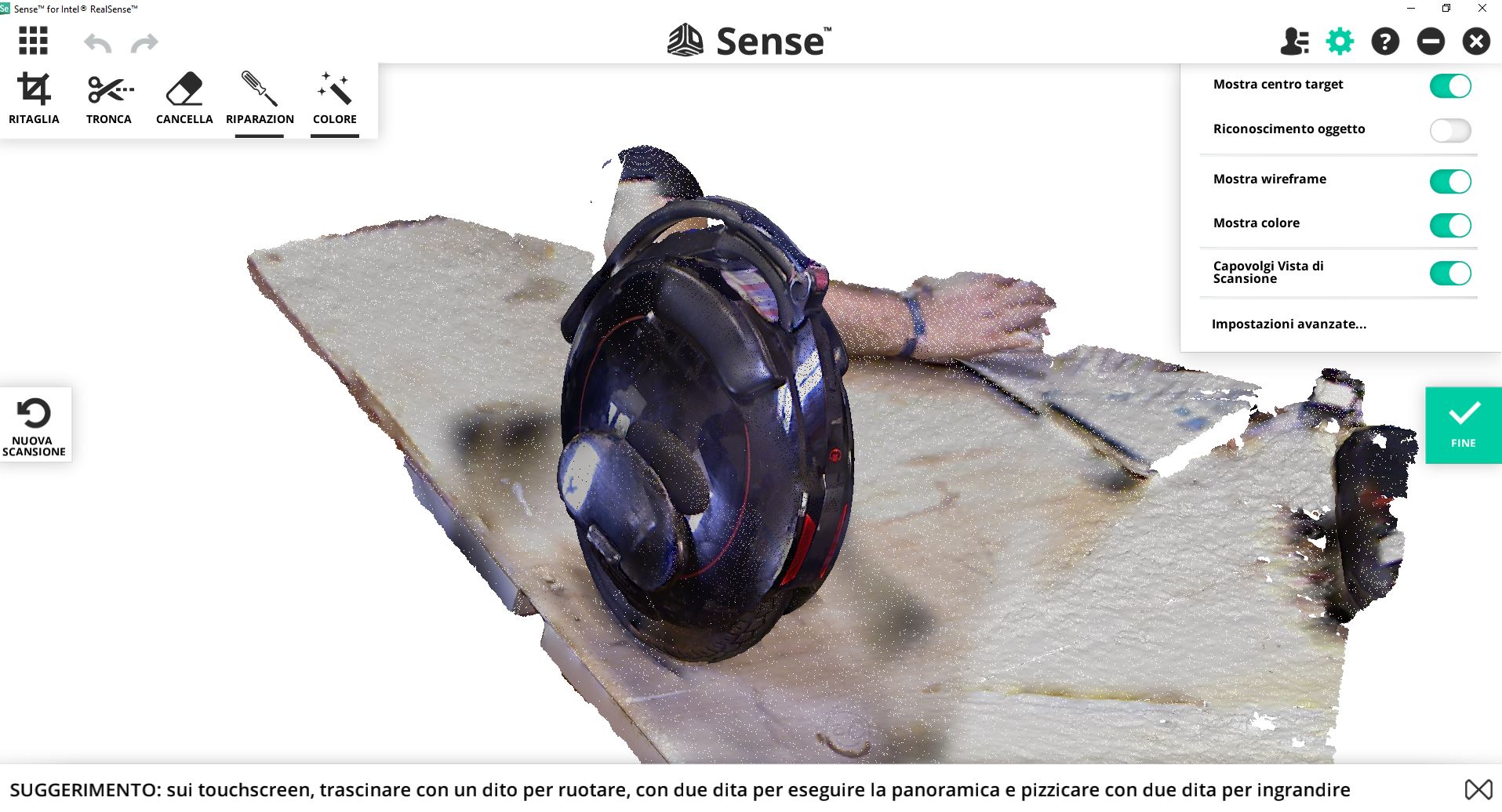
Scanning with Sense
The object for scanning is my EUC (electric unicycle) or just monowheel. It’s involved in the final project as a carrier for my approximation sensing device which would be mounted to the rear side of the wheel. The wheel itself is not very attachment-friendly and it is not possible to power supply my device from the monowheel so I would require some mounting solution to hold the device with battery.
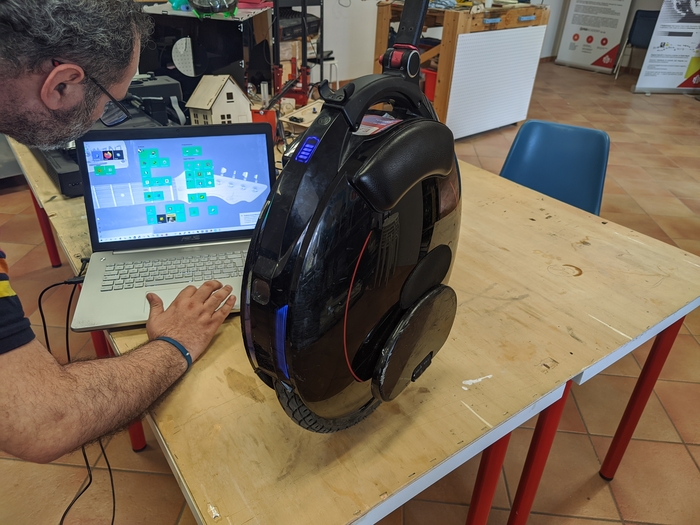
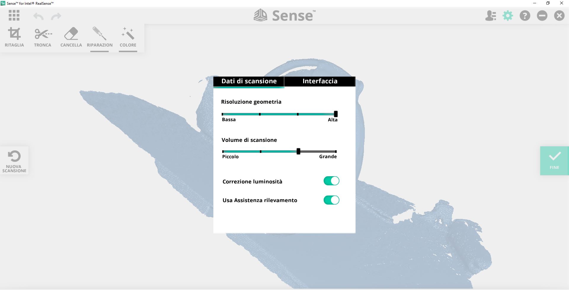
The scanning process is straightforward and easy. After setting up the few settings available in Sense software all what is required is orbiting the objects progressively refining the mesh.
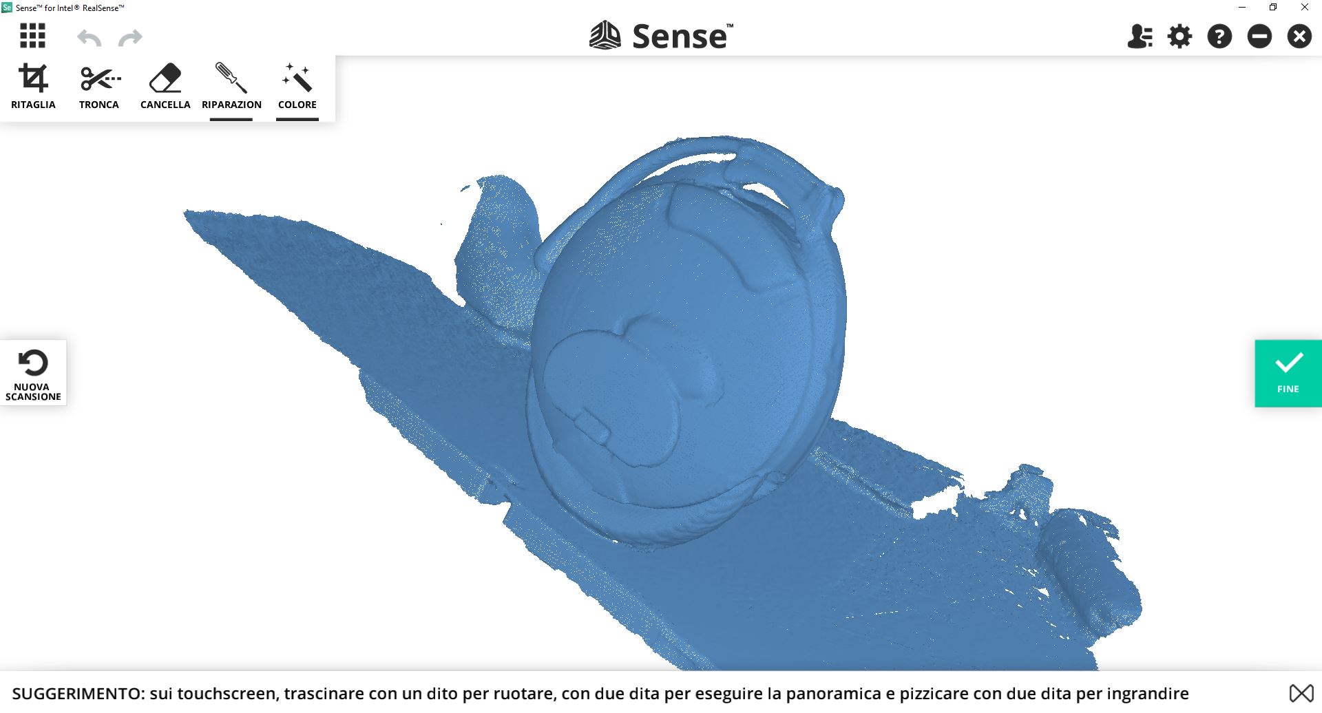
The glossy surface is harder to scan because reflections could distract the scanner and lead to badly built meshes. Also reflections are baked into the textures as you can observe on the next picture.
Preparing files in Meshmixer
What a great tool! After frustrating tries align meshes with Meshlab and looking for other solution in form of Cloud Compare eventually finding this amazing tool from Autodesk which is free and actually very fun to use!
▼ Aligning is flawless!
Just scribble the surface.
▼ Removing redundant mesh
▼ Manual alignment
Taking advantage of the source object symmetrical geometry I’ve been able to rebuild missing surfaces from a single scan using mirror in two planes and some hole closing
▼ Hole closing
Now it’s closed and could be eventually exported, sliced and printed.
▼ Extra