Networking and communications
This week I’m trying to proceed with previous idea and get rid of the wires also increasing the range of “sensing” adding more sensors via I2C. To use feedback-band with ease getting rid of the wires between leg and processor are required. To achieve this I will use the nRF24l01p radio breakout board.
New boards
This week I’ve decided to switch the final project, so the next boards are one of the first steps in the development of final project.

Here I’m trying to utilize the UPDI pins as XSHUT to assign addresses for each sensor. Later I will understand that to actually use it high voltage UPDI is required.

That one is a sketch of the radio-receiver, feedback board. I missed that one, so I will utilize Arduino as controller for receiver radio module.
▣ KiCad full project files
Setting the things up
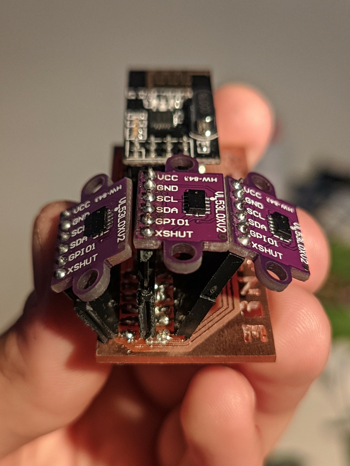
One Attiny 1614 is able to handle all the peripherals and store pretty heavy libraries required for tof sensors and radio breakout, but one sensor doesn’t work. nRF24L01p is using SPI for communicating and the VL530X sensors are connected through I2C bus. Each TOF sensor requires dedicated pin for XSHUT. Those 3 pins are needed to shut down senors while keeping one active to assign the addresses for each device. The last free pin on my board was the UPDI pin, and looking into the pinout it’s clear that it can be used for as A0 input output. The only I was missing is that to utilize the UPDI pin you actually need high voltage UPDI programmer. As I don’t have any HV UPDI in a lab I was not able to use UPDI pin and utilize the third sensor. Nevertheless that was enough for further experimenting.
▼ Network devices
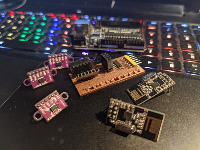
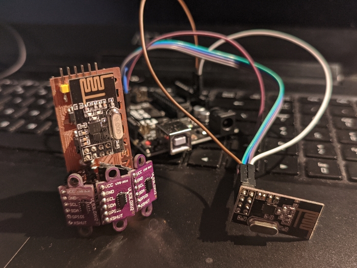
▼ Test setup
The purpose of such board is to achieve some sensing range at some angle in order to be able perceived approaching objects from the sides as well as from the middle.
Arduino programming
Combining examples from this tutorial and code from Pololu forum I was able to make everything talking even with reasonable latency. Of course that is the minimal setup for such device, but I’m happy with that because it proves that this project is achievable with my level of knowledge and training.
▼ It’s alive!
▣ Arduino code
VL53L0-arrray-nRF24-transmitter.ino