WEEK 7
COMPUTER CONTROLLED MACHINIG
Group assignment:
Do your lab’s safety training.
Test runout, alignment, fixturing, speeds, feeds, materials, and toolpaths for your machine.
Individual assignment:
Make (design + mill + assemble) something big (~meter-scale).
Extra credit: do not use fasteners or glue.
Extra credit: include curved surfaces.
Extra credit: use three-axis toolpaths.
COMPUTER CONTROLLED MACHINIG
For this group assignment, we worked with a large-format CNC machine to understand the complete workflow of computer-controlled machining. The objective was not only to operate the machine, but also to evaluate the main variables that affect machining quality and safety, such as alignment, material fixation, spindle speed, feed rate, plunge rate, cutting depth, and toolpath strategy.
We used a ShopBot PRSAlpha 96x48 CNC router. The toolpaths were prepared in Aspire, and the machining process was executed using ShopBot3.
As part of our testing process, we fabricated a square test and a comb test to evaluate press-fit behavior, material tolerance, and joint adjustment. These test pieces helped us understand how tightly the joints fit and how the machine, the tool, and the material interact in real cutting conditions.
The square test had an outer size of 150 mm x 150 mm and an internal square cutout of 50 mm x 50 mm. The comb test had overall dimensions of 420 mm x 100 mm and included multiple slots with widths of 18.00, 18.25, 18.50, 18.75, 19.00, 19.25, 19.50, 19.75, and 20.00 mm. These variations allowed us to compare how the real material thickness and machining tolerance affected the final fit.
In both test pieces, we added dogbones in the internal corners and internal teeth/slots. These reliefs were important because the milling bit is round and cannot produce a perfect sharp internal corner. By adding dogbones, the internal joints became easier to assemble and the press-fit evaluation became more realistic.
The comb test reference used in our practice was adapted from the Fab Academy documentation of Silvana Espinoza, whose Week 7 page served as inspiration for this type of fit evaluation. We used that reference as a starting point and then adjusted it to our own machine, material thickness, and machining parameters.
View Group Assignment Page
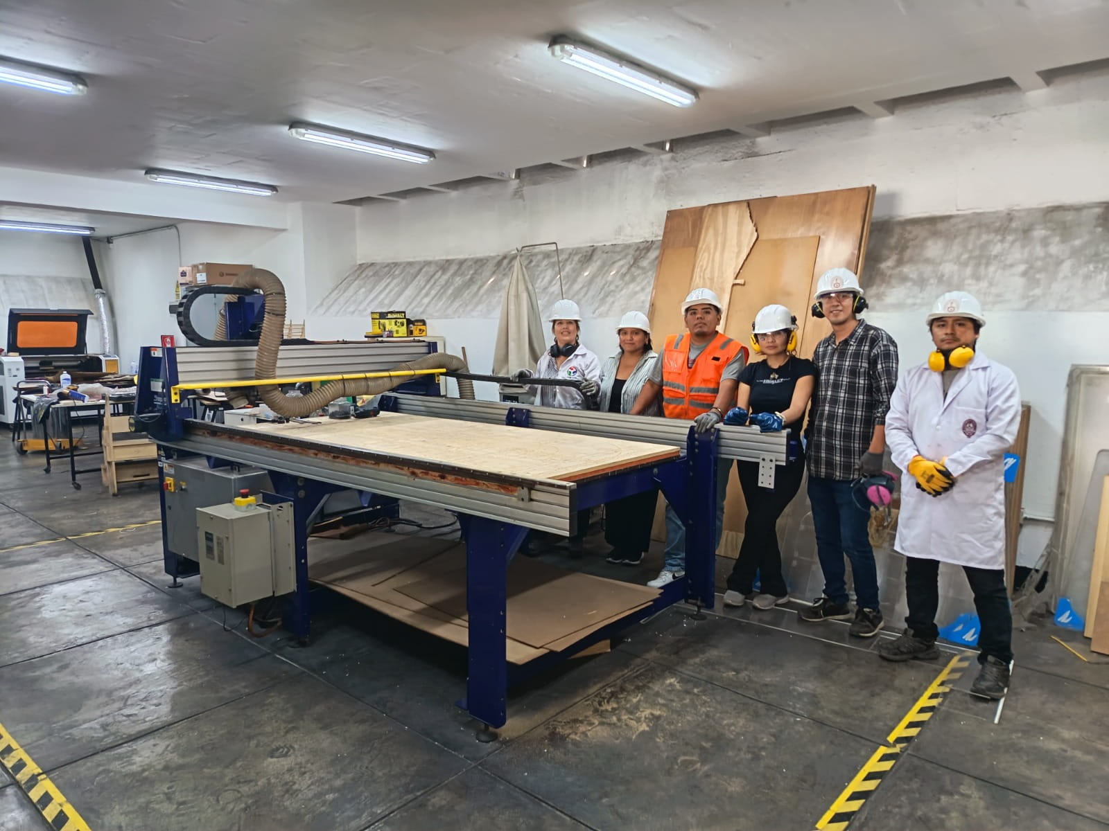
Hero shot of our group assignment with the ShopBot PRSAlpha 96x48.
Group information
Group: Fab Academy 2026
Lab: Fab Lab UNI
- Carmen Elena Gutierrez Apolinario
- Grace Karim Schwan Silva
- Jianfranco Hugo Bazan Jose
- David Isai Avila Pimentel
- Cindy Marilyn Crispín Espinal
- Esteban Miguel Valladares Granda
- Jenifer Wong
- Rocio Maravi
- Mario Chong
Safety training
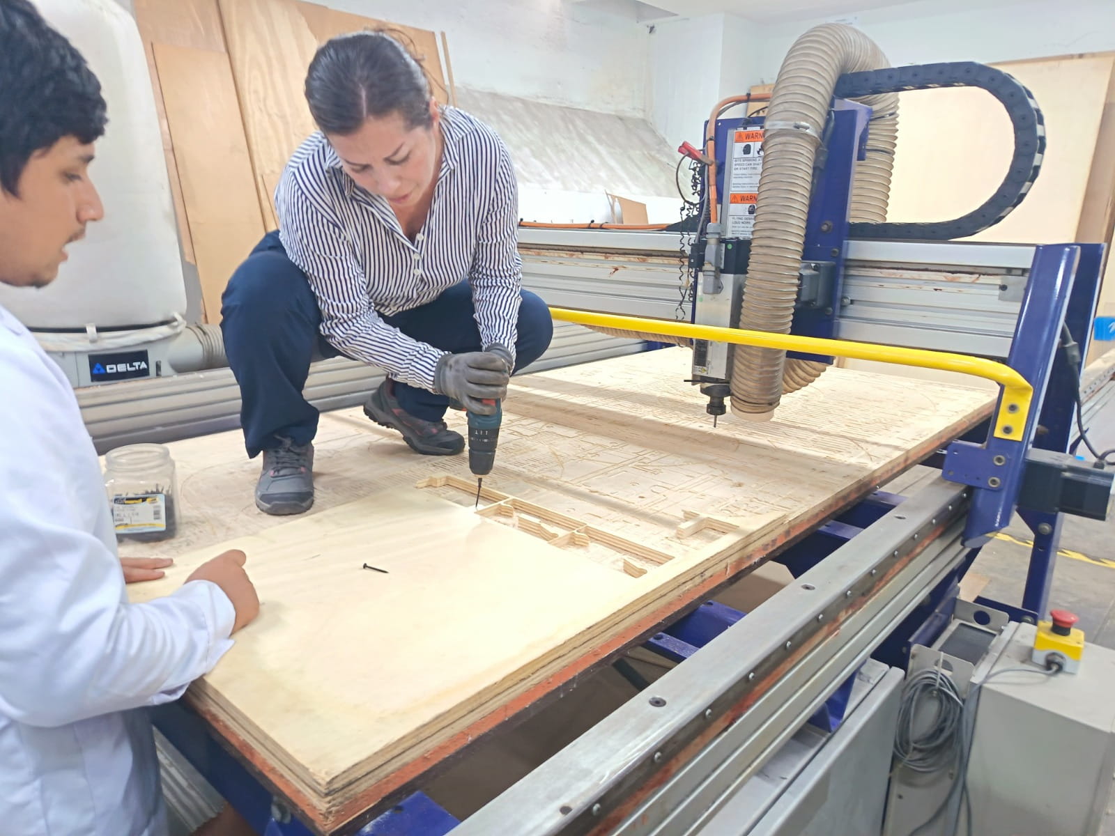
Before operating the machine, we received a safety briefing from Jefferson Lados Villegas, Operational Laboratory Equipment Specialist. During this induction, we reviewed the personal protective equipment required before handling the machine and the material, as well as the safety conditions of the workspace.
The training included mandatory use of PPE, machine safety zones and floor markings, emergency stop procedures, machine startup system, safe interaction with the control software and physical controls, and keeping the work area clean and clear before operation.
We were instructed to use proper clothing and protection, including gloves, safety glasses, hearing protection, helmet, and in some cases a lab coat or protective clothing, as well as closed shoes and appropriate long clothing.
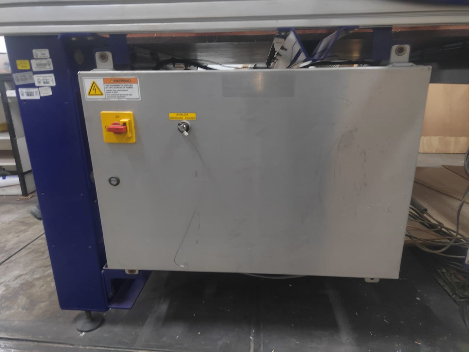
We also identified the machine’s emergency stop button, located next to the machine, and the startup key used to enable machine operation.
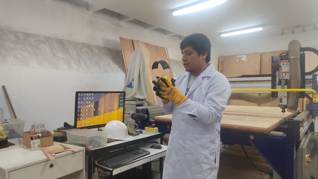
Safety induction before operating the CNC machine.

Dry chemical fire extinguisher available near the work area.
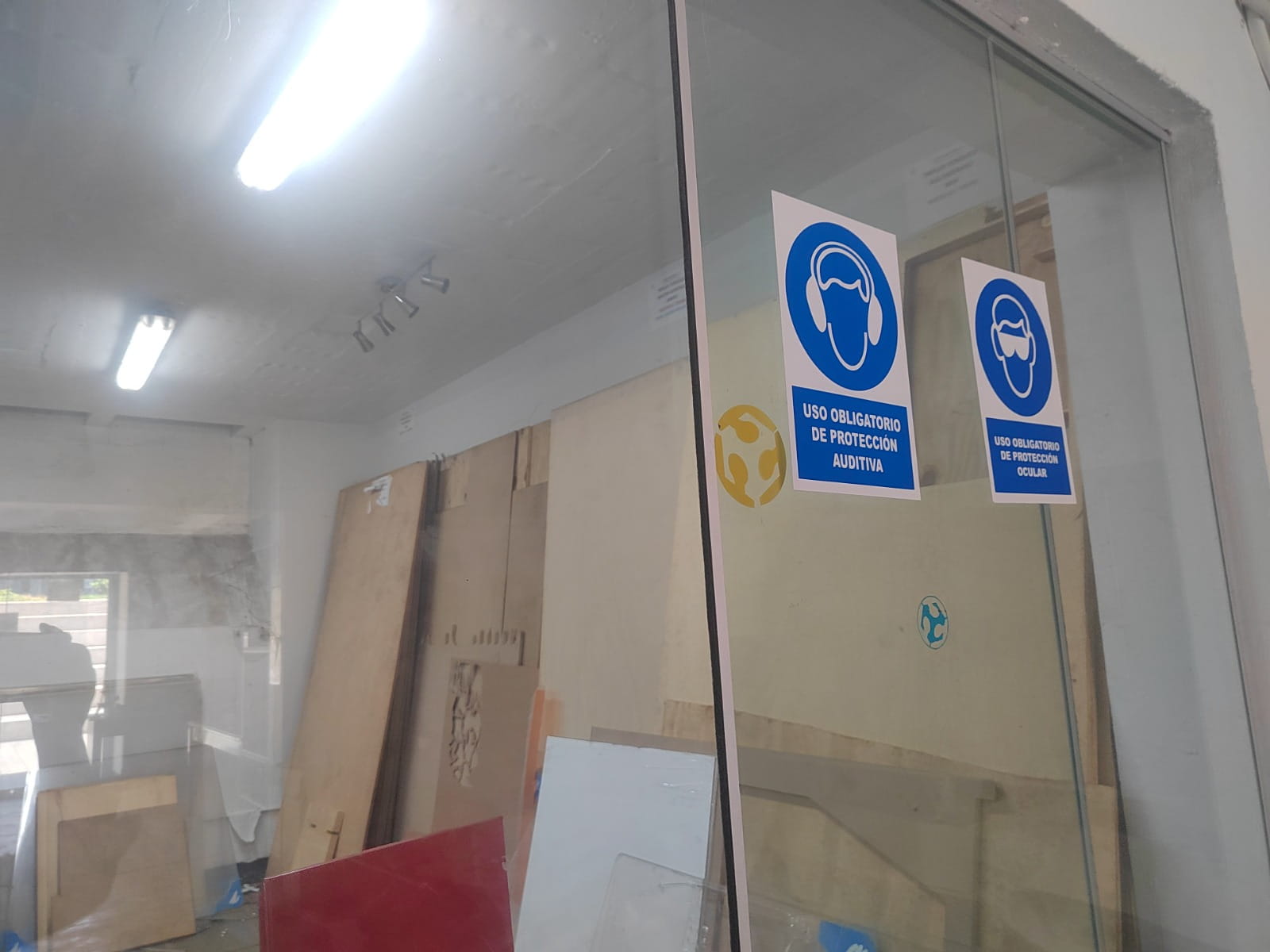
PPE signage showing mandatory safety equipment.

Marked safety line and controlled machine area.
Safe workspace and protective measures
Before turning on the machine, we checked that the workspace was clear, the sacrificial bed was clean, there were no objects interfering with the machine path or operator movement, the safety area was clearly marked, the required PPE was being used, and a dry chemical fire extinguisher was available nearby.
This step helped us understand that safe CNC machining depends not only on the machine itself, but also on preparation of the environment and operator awareness.
Machine, material, and tooling
The machine used in this assignment was a ShopBot PRSAlpha 96x48.
For the test, we used a piece of plywood with a thickness of 18 mm and approximate dimensions of 330 mm x 560 mm. The material was fixed to the sacrificial bed using screws in order to avoid movement during machining.
The cutting tool used was a 6 mm End Mill, 2 edges, up/down cut.

ShopBot PRSAlpha 96x48 used during the assignment.

Plywood board used for the test cuts.
Material placed and fixed on the sacrificial bed.

Detail of the spindle and cutting tool.
Test setup and machining parameters
The first test was carried out on a scrap piece of plywood available in the lab. This allowed us to perform the necessary checks while using a material with dimensions suitable for the design.
- Tool type: End Mill
- Diameter: 6.0 mm
- Flutes: 2
- Cut type: Up/Down cut
- Pass depth: 3.0 mm
- Stepover: 3.0 mm (50%)
- Spindle speed: 15,000 rpm
- Feed rate: 4500 mm/min
- Plunge rate: 1200 mm/min
- Tool number: 1
Because the board thickness was 18 mm and the pass depth was 3 mm, the machining required approximately 6 passes to go through the material.
What we tested
- Material fixation: the plywood board was fixed to the sacrificial bed using screws.
- Initial zeroing in X, Y, and Z: we first set the machine reference after placing the material on the bed.
- Recalibration after fixation: after placing the board and doing the initial setup, we fixed the material with screws and then calibrated the machine again, especially on the X and Z axes.
- Alignment: we checked that the board was properly placed and aligned relative to the machine bed.
- Feeds and speeds: we observed how spindle speed, feed rate, and plunge rate affect the cut.
- Depth per pass: the cut was divided into multiple passes.
- Toolpath strategy: we used a 2D Profile Toolpath and considered tabs.
- Press-fit testing: we produced a square test and a comb test. The square test measured 150 mm x 150 mm with an internal square of 50 mm x 50 mm. The comb test measured 420 mm x 100 mm and included slots from 18.00 mm to 20.00 mm in increments of 0.25 mm.
- Dogbone geometry: we added dogbones in the internal corners of the square test and in the internal teeth of the comb test.
- Tabs: tabs were added in both tests to keep the internal pieces attached during machining and prevent them from moving or flying out while cutting.
Workflow
- The vector design was created in a CAD environment such as Fusion or Rhino.
- The design was exported and imported into Aspire.
- In Aspire, the material dimensions and the origin point were configured.
- The cutting tool was selected as a 6 mm end mill.
- The main machining parameters were defined: pass depth, stepover, spindle speed, feed rate, and plunge rate.
- A 2D Profile Toolpath was generated, selecting the cutting side and adding tabs where necessary.
- Dogbones were added to the internal corners of the test pieces to improve internal fit.
- The toolpath was simulated in Aspire to verify the process and detect possible errors before machining.
- Once verified, the file was exported for ShopBot machining.
- The plywood board was placed onto the CNC machine bed.
- An initial machine reference was set.
- The board was fixed with screws to the sacrificial bed.
- After fixation, the machine was calibrated again, especially on the X and Z axes, to ensure correct positioning before machining.
- The tool was installed in the spindle.
- The file was loaded into ShopBot3 and the cutting process was started.

Machine detail before machining.
Machine setup and operator interaction in the lab.
Results
Press-fit tests
As part of our testing process, we fabricated a square test and a comb test to evaluate press-fit behavior, material tolerance, and joint adjustment.
The square test had an outer size of 150 mm x 150 mm and an internal square cutout of 50 mm x 50 mm. The comb test had overall dimensions of 420 mm x 100 mm and included slots from 18.00 mm to 20.00 mm in increments of 0.25 mm.
Square test
The square test was used to evaluate the internal fit of a smaller square inside a larger frame. We added dogbones in the internal corners to compensate for the round shape of the milling bit. We also added tabs so that the internal part would remain attached during machining and would not move or fly out during the cut.

Square test design in Aspire with dogbones and tabs.

Finished square test after machining.

Square test during machining on the CNC machine.
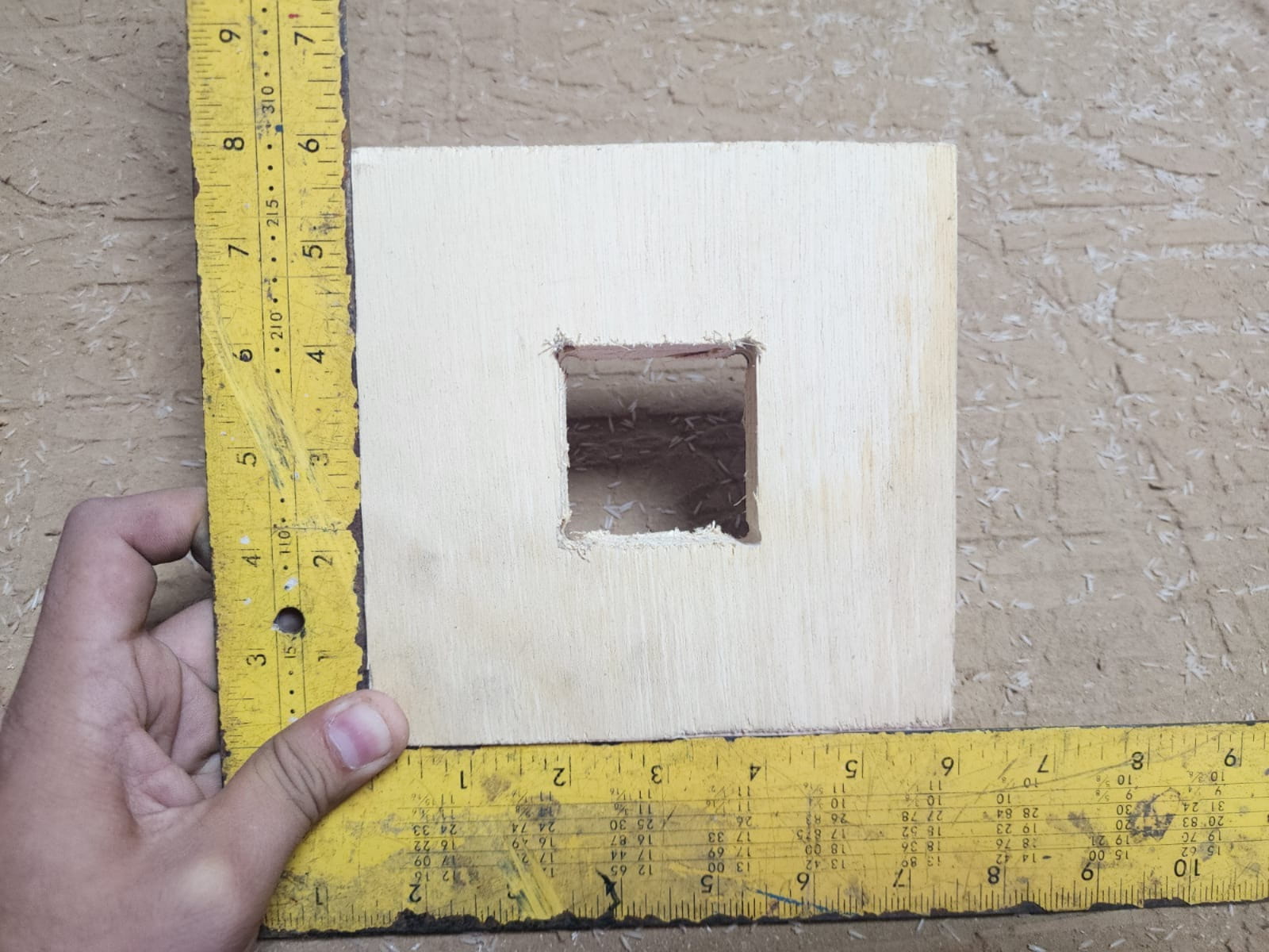
Square test result to verify the accuracy of the internal square cut.
Comb test
The comb test was used to compare different slot widths and identify the best press-fit according to the real material thickness and machining tolerance. This design included slots of 18.00, 18.25, 18.50, 18.75, 19.00, 19.25, 19.50, 19.75, and 20.00 mm. We also added dogbones in the internal teeth and tabs to keep the internal parts stable during machining.
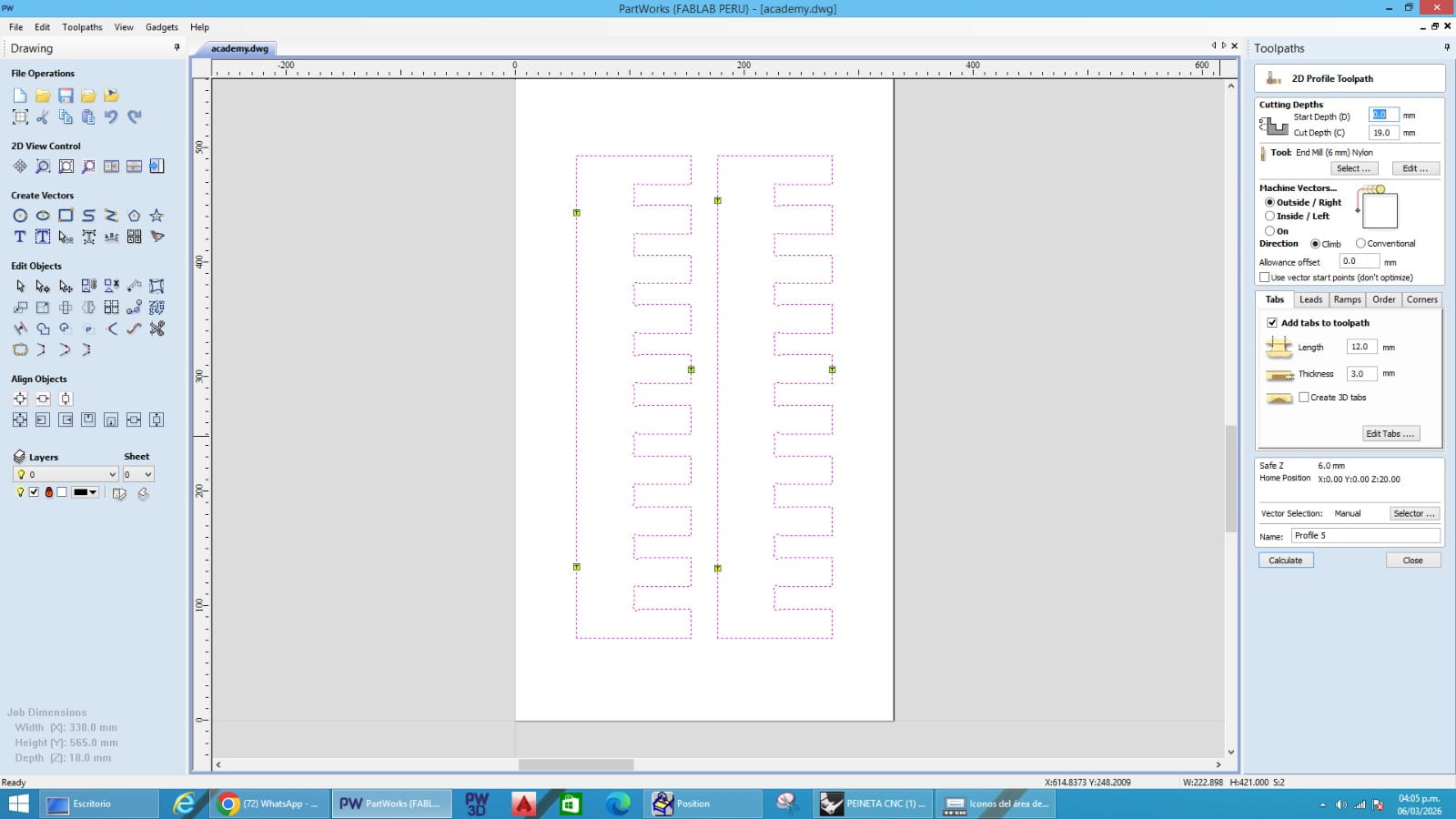
Comb test design in Aspire with slot variations, dogbones, and tabs.

Comb test during machining on the CNC machine.
Finished comb test after machining.
Comb test used to evaluate press-fit tolerance with slot widths from 18.00 mm to 20.00 mm.
Problems and solutions
No major problems occurred during the test. The machining process was completed without critical errors such as tool breakage, material displacement, incorrect zeroing, or failed cutting.
One important observation was that, after placing the material and making the initial setup, the board had to be fixed with screws, and this required a second calibration step, especially on the X and Z axes. Rechecking the machine reference after fixation was important to maintain accuracy before starting the cut.
Another relevant observation was the rough edge finish, mainly due to the plywood structure and the natural tendency of this material to splinter during machining. This was not a machine failure, but rather a material behavior that should be considered in design and finishing stages.
To improve assembly, we used dogbones in the internal corners of the square and comb test pieces. This made the internal joints easier to fit and improved the press-fit evaluation.
If a smoother result is required in future jobs, possible improvements would include using a better-quality plywood or a different board material, optimizing toolpath direction, adjusting feeds and speeds, using a finishing pass, and sanding the edges after machining.
What we learned as a group
As a group, we learned that large-format CNC machining is not only about sending a file to the machine. It requires preparation, safety awareness, correct machine setup, suitable cutting parameters, and proper fixation of the material.
We understood that safe operation begins before the machine starts, toolpath simulation is essential to prevent mistakes before cutting real material, zeroing the machine correctly is one of the most important steps in the process, recalibration after fixing the board can be necessary to maintain accuracy, and feeds, speeds, and pass depth directly affect cutting quality, machine stability, and tool performance.
We also learned that press-fit tests are very useful for understanding material tolerance and joint behavior, that dogbones improve internal fit in CNC-milled joints, and that material behavior matters because plywood can produce rough edges and requires finishing.
Conclusion
This group assignment allowed us to document and understand the workflow of large-format CNC machining using the ShopBot PRSAlpha 96x48. Through this exercise, we practiced safety procedures, prepared material and toolpaths, configured machining parameters, and executed a successful test cut on plywood.
The experience helped us connect digital design with physical fabrication and gave us a better understanding of how machine setup, parameter selection, material behavior, and safety practices influence the final result.
The use of the square test, comb test, and dogbone-adjusted joints made the assignment more useful for evaluating real press-fit conditions, which is valuable for future CNC construction projects.
Reference
The comb test used in this assignment was adapted from the Fab Academy Week 7 documentation of Silvana Espinoza and then adjusted to our own machine, material thickness, and machining parameters.
Reference Page
Files used in this assignment
INDIVIDUAL ASSIGNMENT
Make (design + mill + assemble) something big
This was one of the assignments that I enjoyed the most. From the moment I started sketching my idea on paper, I felt very excited because this design was very special to me. I made it for my granddaughter Lara, who loves painting and drawing. She is 2 years old and full of creativity and energy.
For this reason, I decided to fabricate an easel so she could place her canvases and paint comfortably.
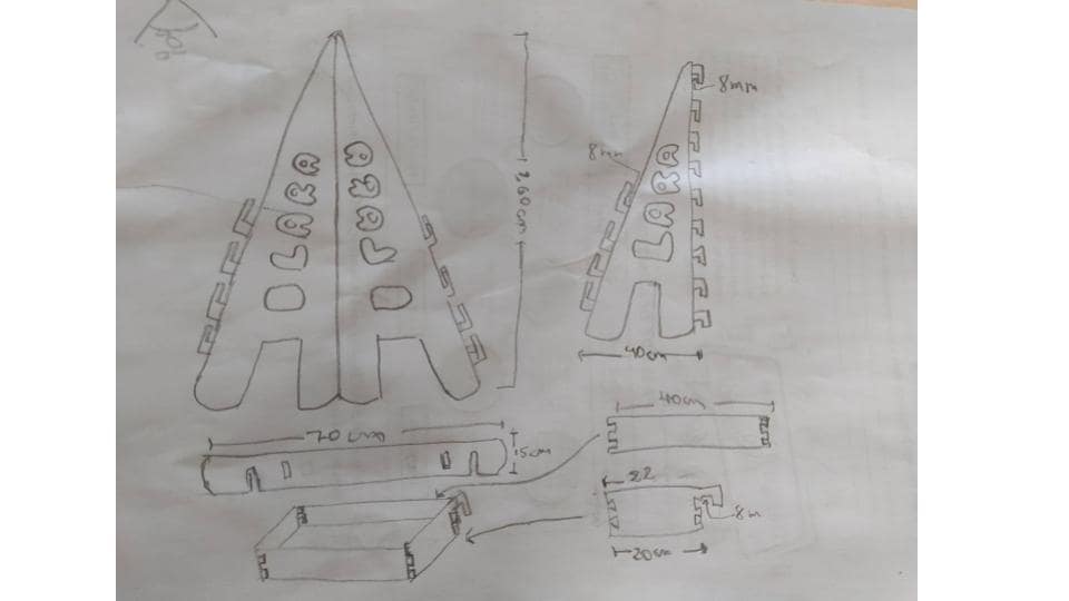
Initial sketch of the easel designed for my granddaughter Lara.
Concept and proposal
Before starting the digital design, I thought about what kind of object I wanted to make, how it should work, and who would use it. Since the easel was designed for a child, I wanted it to be functional, stable, safe, and easy to assemble.
First, I made a hand sketch to visualize the overall shape, the pieces, and the structure of the easel. This helped me organize the idea better before moving to the computer.
Design in Rhinoceros
To develop my project, I used Rhinoceros 3D. In this case, I worked in 2D, since the CNC machine required a vector file in order to cut the pieces.
At the beginning, I had some problems because several lines were not completely joined. At first glance, the design seemed finished, but when I tried to prepare the geometry for machining, I realized that there were still open or disconnected parts. Little by little, I corrected those mistakes until I completed the file correctly.
This stage taught me an important lesson: before arriving at the machine, the design must be fully finished and carefully checked. It is also necessary to review the cutting files in advance so as not to waste either my time or the time of the person providing support.
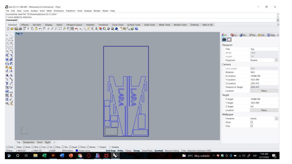
2D easel design in Rhinoceros.

Checking and correcting the geometry before exporting the file.
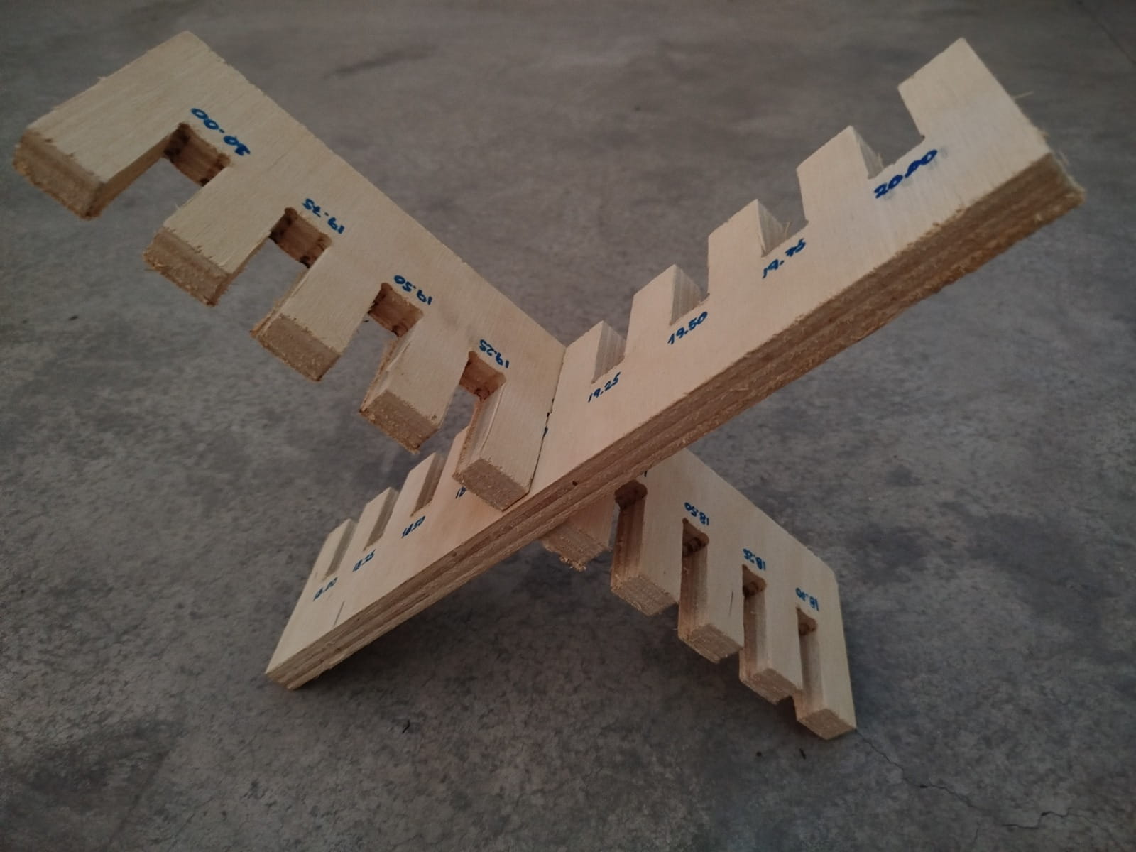
Tolerance test
Before cutting the final pieces, I performed a tolerance test to verify whether the joints would actually work. This test helped me better understand the relationship between the real material thickness, the slot width, and the behavior of the cut on the CNC machine.
In this test, I found that a value of 9.4 mm worked well for a 9 mm board, so I used that value as a reference to adjust the easel joints.
This test was very important because it allowed me to avoid errors in the final project and ensure a better assembly.
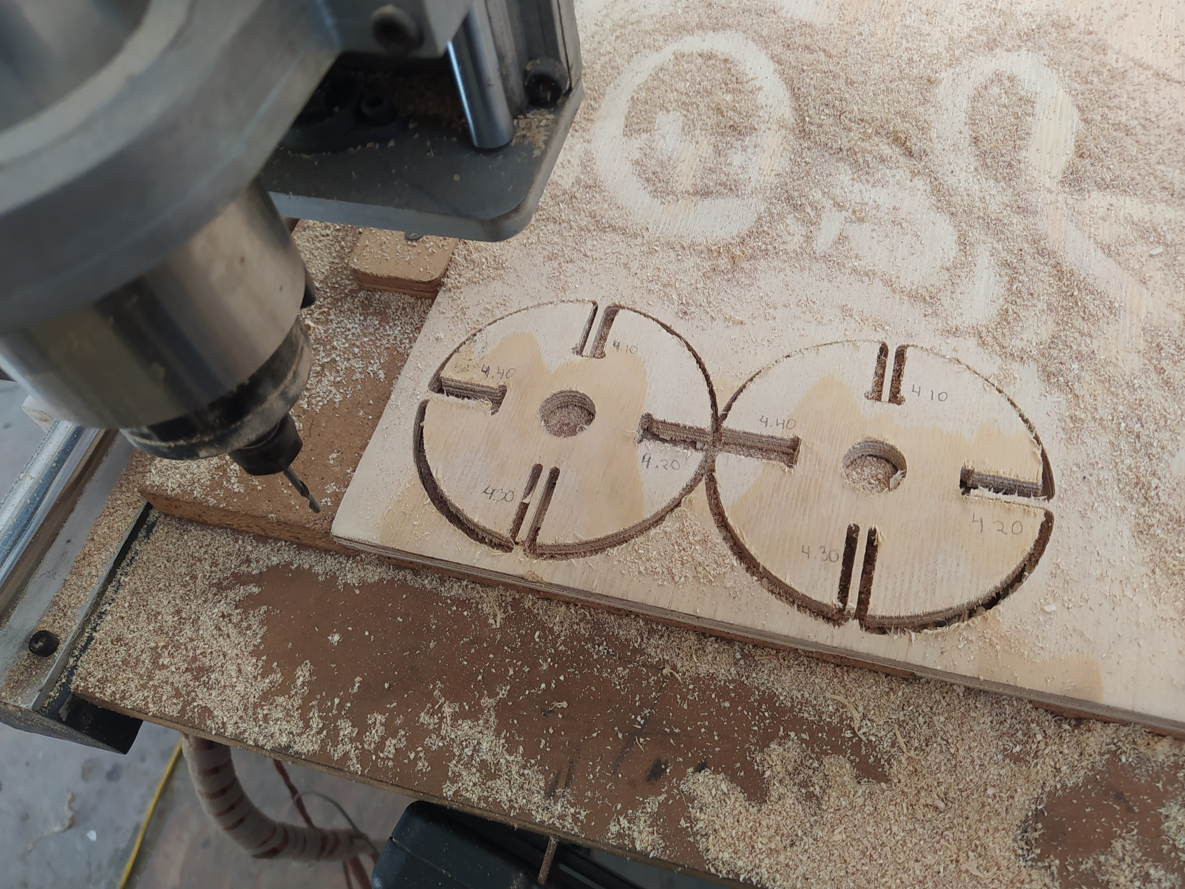
Radial tolerance test used to evaluate the real slot fit.
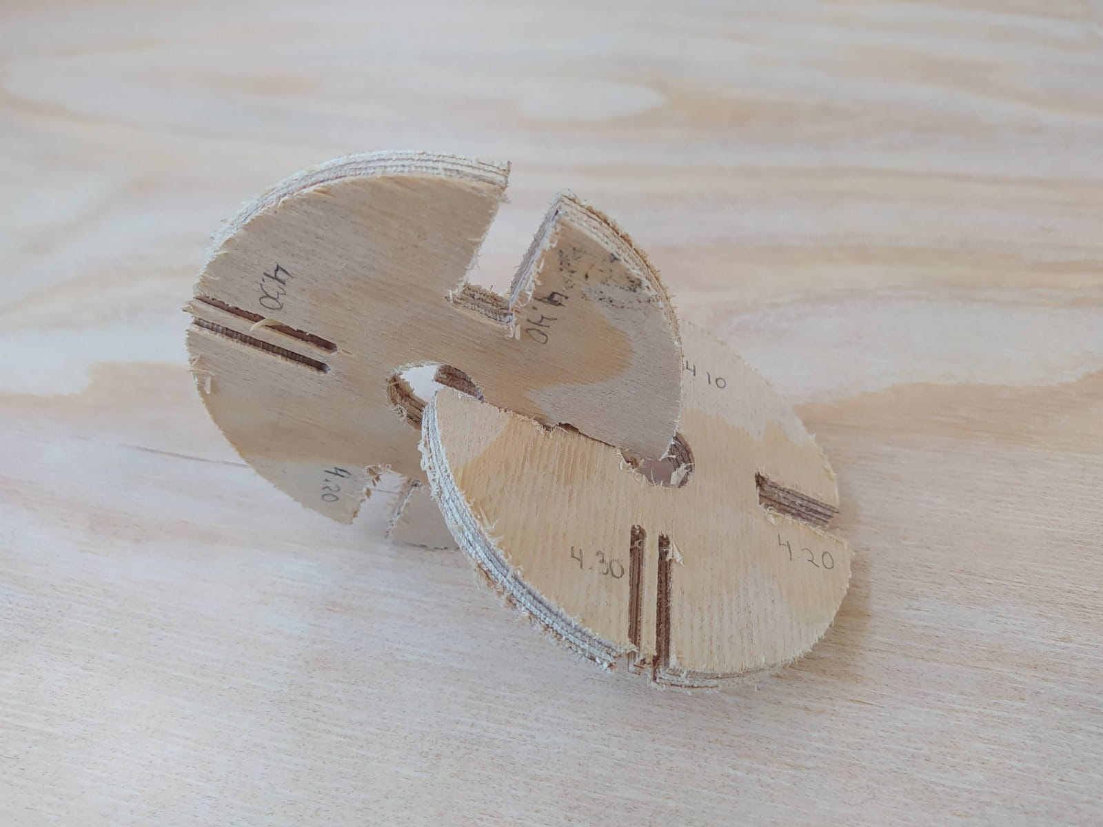
Result of the tolerance test; 9.4 mm worked well for 9 mm material.
Preparing the file in ArtCAM
After finishing the design in Rhinoceros, I exported the file and prepared it in ArtCAM Pro to generate the cutting toolpaths.
In ArtCAM, I configured the material with a working area of 1220 mm x 2440 mm and defined a material thickness of 9.0 mm, since I worked with a phenolic board of that thickness.
The Z zero was placed on the top of the material, with Top Offset = 0.0 mm and Bottom Offset = 9.0 mm.

Initial layout of the easel parts in ArtCAM.

Final arrangement of the parts on the board before generating the toolpaths.
.jpg)
Material setup: 9 mm thickness and Z zero on the top surface.

Detail of the cutting toolpaths generated in ArtCAM.
Cutting parameters
For the machining process, I used a Slot Drill tool with the following settings visible in the file:
- Tool type: Slot Drill
- Tool diameter: 3.175 mm
- Tool number: 1
- Material thickness: 9.0 mm
- Spindle speed: 10,000 rpm
- Feed rate: 30.0 mm/sec
- Plunge rate: 5.0 mm/sec
- Stepover: 0.5397 mm
- Stepover (%): 17%
- Cut direction: Climb Mill
- Home position: X0, Y0, Z10
With these parameters, I prepared the Profiling toolpaths, checking the simulation beforehand to make sure the cut would follow the expected route.

Tool configuration: 3.175 mm cutter, 10,000 rpm, 30 mm/s feed rate, and 5 mm/s plunge rate.

Profiling toolpath configuration in ArtCAM.
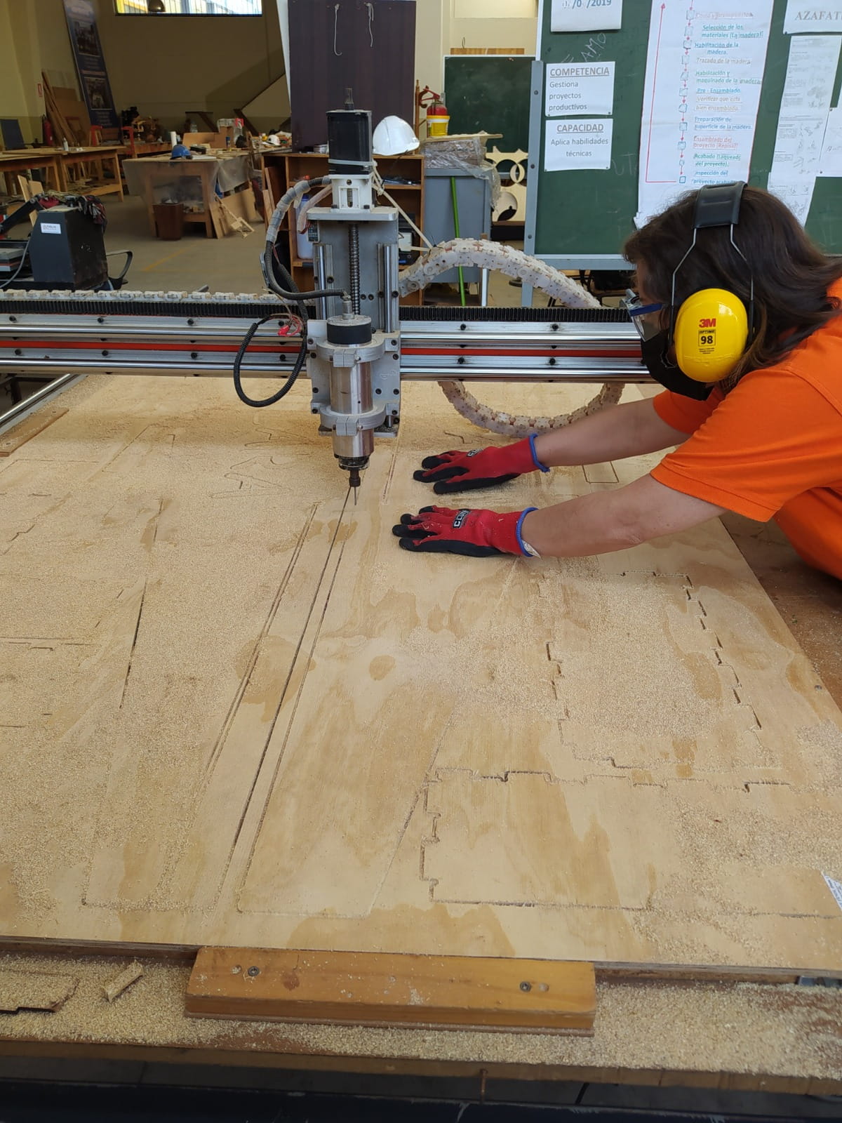
Safety and machine preparation
Before using the CNC machine, I considered several safety measures. The first priority was always to wear safety glasses, hearing protection, gloves, proper clothing, and closed shoes.
It was also important not to wear chains, long earrings, bracelets, or loose hair, because these could get caught in the machine or in the cutting tool and cause an accident.
Another important point was to verify that the cutter was the correct one and that it was properly tightened. Then I had to place the material on the sacrificial bed and make sure it was firmly fixed. I also had to check that the screws did not interfere with the cutting path.
During machining, it was necessary to turn on and calibrate the machine, check the Z axis, and constantly monitor that the machine followed the programmed route correctly.

CNC router used to cut the easel parts.
.jpg)
Phenolic board properly fixed on the sacrificial bed.

RichAuto controller used to monitor coordinates and machine status.

Monitoring the machining process during file execution.
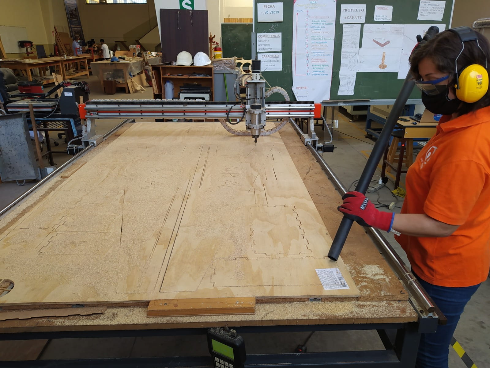
Machining process
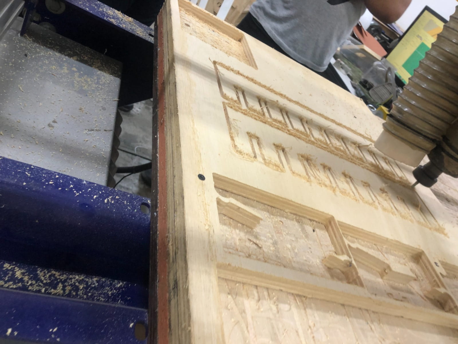
Once the file was prepared and the toolpaths were verified, I proceeded to cut the easel parts on the CNC machine. This moment was very exciting because it was when the digital design started to become a real object.
During the process, I stayed attentive to the cut, observing the toolpath, the stability of the material, the behavior of the cutter, and the overall progress of the machining.
Monitoring the cut was very important because no one knows the design better than the person who prepared it.

Tracking the process from the RichAuto controller.
Checking the machine status during file execution.
Problems and how I fixed them
During the cutting process, an important problem appeared: the milling bit broke.
At that moment, one of my teachers explained to me that sometimes boards are not perfectly level. In my case, I was using a 9 mm phenolic board, and apparently one part of the material had some unevenness. Since there was already a previous cut in that area and another path was generated very close to it, the material started to vibrate. This movement forced the tool and caused the bit to break.
To solve this problem, I changed the damaged bit, reviewed the cutting path more carefully, and paid closer attention to the stability of the material and to the route of the tool. After making those adjustments, I was able to continue and finish the cut correctly.
This problem taught me an important lesson, because I understood that not only the digital design matters, but also the real physical conditions of the material during the process.

Moment during the process when cutting difficulties appeared.

Continuing the work after changing the bit and reviewing the toolpath.
After the cut
Once the machining was finished, it was necessary to clean the machine and the working area. If the machine does not have an integrated dust extraction system, it is important to remove all chips and residues produced during the cut.
After that, the material must be unscrewed, removed carefully, and the area must be cleaned again. This stage is also part of responsible machine use.
Pieces removed from the board after the cutting process was completed.
Assembling the easel
After removing the pieces, I first checked that all of them were complete and correctly cut. Then I started sanding them to improve the finish and remove rough edges.
After that, I identified each piece and began assembling the easel to verify that everything fit and worked correctly. This stage was very important because it confirmed that the design decisions and the tolerance test had been correct.

Sanding the pieces to improve the finish.

Assembly process of the easel.

Checking the structure before the final result.
Final result
The final result was a large CNC-milled easel designed for a small child. This project allowed me to integrate design, digital fabrication, machining, finishing, and assembly into a single assignment.
It was also especially meaningful to me because it was not only a technical exercise, but also a personal project made with a lot of affection for my granddaughter.
When I finally took it home, she received it with a lot of excitement, and that made the whole process even more special.

Final result of the CNC-milled easel.

Hero shot of the final product.
What I learned
This assignment gave me many important lessons. I learned how to prepare a design for CNC machining, I understood the importance of having clean and closed lines, and I confirmed that tolerance tests are essential before the final cut.
I also learned how to configure the material, the tool, and the toolpaths in ArtCAM, and I reinforced the importance of safety before, during, and after machining.
Another very important lesson was understanding that the real conditions of the material, such as unevenness and vibration, can strongly affect the result. CNC machining is not only about cutting parts, but also about understanding the relationship between design, material, machine setup, safety, and assembly.
Checklist
- [ ] Linked to the group assignment page
- [ ] Reflected on your individual page what you learned of your lab’s safety training
- [ ] Documented how you designed your object and made your CAM-toolpath
- [ ] Documented how you milled and assembled your final product (including setting up the machine, fixturing, feeds, speeds etc.)
- [ ] Described problems and how you fixed them
- [ ] Included your design files and “hero shot” of your final product
Design files
Here I will include the files related to the design, the toolpaths, and the documentation of the easel project.